
Abstract
The hydrogen assisted cracking susceptibility of Modified 9Cr–1Mo steel weld is evaluated by implant test by determining lower critical stress for different preheating and combination of pre, post heating conditions. The diffusible hydrogen present in the implant specimens for different test conditions is estimated. Residual stress distribution in the weld for different heating condition is estimated using SYSWELD software. For a combination of pre + post heating at 200°C, the diffusible hydrogen content of the weld comes down to 1.17 from 4.7 mL/100g and the lower critical stress of the implant specimen increases from 250 to 370 MPa. Preheating + post heating also brings down the peak tensile residual stress level in the weld joints and lowers the cracking susceptibility.
Keywords
Introduction
Hydrogen assisted cracking (HAC) is a serious concern during welding of highly alloyed martensitic steels. HAC occurs with time delay, often at ambient temperature, hours or days after completion of the welding before it is subjected to any post weld heat treatment [1]. The factors responsible for HAC are the presence of diffusible hydrogen, susceptible microstructure and high tensile stress in the weld. The possible sources of hydrogen are the welding consumables, atmospheric moisture, undesired hydrocarbon residue present due to improper cleaning during welding, application of insufficient shielding gas etc. [1]. The as-quenched martensitic microstructure in the weld with hardness more than 400 VHN or so is highly susceptible to HAC, whereas bainitic or ferritic microstructure is less susceptible [1, 2]. The residual tensile stresses derived from the steep thermal cycle and weld geometry, structural restraint provided during welding etc. aggravate the occurrence of HAC [3]. The use of low hydrogen electrode and shielding gas, proper baking of electrode and maintenance of clean surface can bring down the hydrogen in the weld. To avoid formation of a susceptible microstructure during welding, control of heat input and application of preheating, post heating, etc. are generally practised. Slow cooling aided by high heat input and preheating leads to less hardening of the weld. However, for high alloy ferritic steels, it is difficult to prevent formation of martensite in the weld metal (if matching composition of the welding consumable is used) and heat-affected zone (HAZ) by varying the welding parameters. Hence reducing the diffusible hydrogen in the weld is the best option available to prevent HAC of this class of steels. Preheating reduces the cooling rate of the weld offering more time for hydrogen to diffuse out before the weld is cooled down to ambient temperature. Similarly, post heating, is beneficial for hydrogen to diffuse out from the weld. The residual stresses, which remain in the component after completion of the welding, play a major role in HAC of welds. The residual stresses arise from the steep thermal gradient and non-uniform temperature distribution in the weld and HAZ due to the application of highly concentrated and instantaneous heat source during welding and phase transformation of the material involved in heating and cooling cycles of welding [4].
Various test methods are followed to assess the HAC susceptibility of steel welds. These tests are categorised as self restraint and external restraint test. The susceptibility of a weld to HAC can be quantified by implant test, which is an external restraint test and determines the Lower Critical Stress (LCS), the stress below which the weld does not fracture [5-7]. However, this test cannot be used to study the role of diffusible hydrogen present in the weld on HAC; because it is not practically possible to estimate the diffusible hydrogen present in the implant test specimens. As a result, for given steel, direct correlation between the diffusible hydrogen content in the weld and the risk of cracking is difficult.
Modified 9Cr–1Mo (P91) steel has been extensively used in fossil power plants and nuclear power plants for its superior high temperature creep strength. Due to the high hardness and martensitic microstructure developed in the weldmetal and HAZ, P91 steel weld joints are highly susceptible to HAC. In the present study, HAC susceptibility of P91 steel weldments has been assessed by implant test and LCS, below which HAC is unlikely to occur in the as-welded condition, is determined for different preheat and preheat + post heating conditions. Further, diffusible hydrogen present in the implant test coupons made with different preheat and pre + post heat conditions is also estimated. This is done by providing heating and cooling arrangements to the copper block used for standard measurement of diffusible hydrogen and using similar welding parameters as that of implant test.
In implant test, apart from the stresses generated due to external loading, the residual stresses derived from the weld thermal cycle also has a role in the cracking. Thus, it is appropriate to assess the residual stresses generated in the specimen due to welding. Numerical simulation through finite element method (FEM) is very useful for predicting residual stresses in weld joints [8, 9]. Recently, residual stresses and distortion developed during welding of P91 steel plates made with preheating and post heating have been modelled using SYSWELD and the results have been validated reasonably well by experiments [9]. Using the same model, residual stresses generated in the implant test has been estimated and effect of preheating and post heating on altering the residual stress levels in implant specimen has been demonstrated. Hence, it has become possible to study the effect of preheating and post heating on both diffusible hydrogen content in the welds as well as the residual stress generated on HAC of P91 steel welds. Although, application of preheat or post heating is a well-adopted method to control the HAC problem of ferritic grade of steel welds, the novelty of the present study is to assess the effect of pre, post heating on all the factors contributing to HAC, i.e. microstructure, diffusible hydrogen and residual stress level of the weld.
Experimental procedures
Implant test
Implant test of P91 steel (C: 0.11, Cr: 8.85, Mo: 0.85, V: 0.21, Nb: 0.008 wt-%) was conducted as per Doc. IIW-802 guidelines [7]. The specimen assembly consists of a baseplate of size 90 mm × 60 mm × 12 mm with an 8 mm diameter through hole at the centre, into which implant specimen is inserted in such a way that the top surface of the implant specimen and baseplate are at the same level. The length of the implant specimen is 56 with 10 mm threaded at the top (acting as a helical notch: 1.5 mm pitch at 40° angle) and 15 mm threaded at the bottom. The top threaded part of the implant specimen is connected to the baseplate, whereas, the specimen is connected to the implant testing machine through the bottom threaded portion. One millimetre diameter hole is provided at the centre of the baseplate in the thickness direction to connect the thermocouple for the measurement of cooling rate. Single-pass bead on plate welding was made on this specimen assembly so that the weld bead passes over the implant specimen fusing its top surface completely with the baseplate. Approximate current and voltage employed during the welding were 90 A and 22 V, respectively. E9018 electrodes (C: 0.08, Cr: 8.69, Mo: 0.99, V: 0.16, Nb: 0.066 wt-%) were baked at 300°C for 2 h prior to the welding. Welding was performed without any preheat or post heat, with preheat only (at 100°, 150° and 200°C) and with a combination of preheat and post heating for 100°, 150° and 200°C. Heating was provided by a resistance heater. The entire test assembly was heated up to the required temperature by direct contact of the baseplate with the resistance heater. A thermocouple was attached to the baseplate to monitor the temperature and time for the test assembly to cool down to 100°C was noted down. The schematic diagram of the test setup is provided in Figure 1. The implant specimen was loaded manually to the desired load level when the assembly cools down to 100°C. Initially, series of tests with no preheat and post heating with first specimen loaded at 1200 kg was conducted. For subsequent specimens, loading was increased up to 1900 kg in steps of 100 kg. The sample was loaded for 24 h or till failure to record the time for fracture of the specimen at the applied load and the corresponding stress was estimated knowing the area of cross section of the specimen. LCS was determined from the applied stress level for which no fracture happens up to 24 h of loading in minimum of two tests.
Schematic diagram of implant test set up.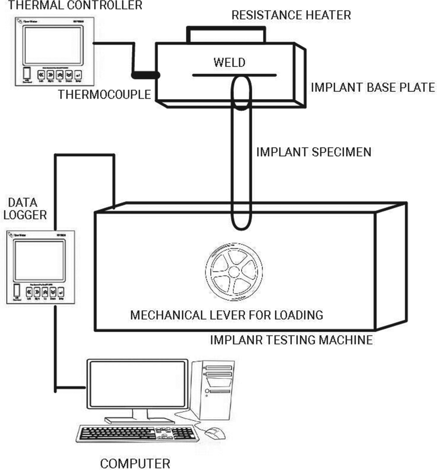
Diffusible hydrogen measurement
To measure diffusible hydrogen content of the electrode, P91 specimen blanks were fabricated as per ISO 3690 specification. The specimen blank of size 30 mm × 15 mm × 10 mm was fixed in a copper jig with run-on and run-off blanks each of size 40 mm ×15 mm × 10 mm on either side. Bead on plate welding was carried out with 3.15 mm diameter grade E9018-B9 electrode, baked at 300°C for 2 h prior to welding. Immediately after completion of the welding the specimen assembly was immersed in ice-cold water for 5 s and kept inside liquid nitrogen to cool to subzero temperature till taken out for hydrogen extraction and measurement. Just before the measurement, the sample was taken out from the liquid nitrogen and the middle segment of the sample was broken off from the run-on, run-off pieces. The middle segment was then cleaned, dried in air flow and inserted in the closed extraction chamber. For diffusible hydrogen measurement the Hot Extraction Gas Chromatograph Thermal Conductivity Detector set up was used. The specimen was kept inside the chamber at 400°C for 30 min for extraction of diffusible hydrogen from the test specimen. Total hydrogen present in the chamber was measured using Gas Chromatograph. Knowing the weight of the deposited weld metal, the diffusible hydrogen content in millilitres per 100 gram of weld metal was estimated. The detail of the measurement procedure is described elsewhere [10].
In order to determine the diffusible hydrogen content of the weld metal corresponding to the same preheating/post heating temperature and cooling time as that experienced by the implant test specimens, a direct contact type resistance heater was used to heat the copper jig to the desired preheat/post heat temperature and the temperature was maintained by a temperature controller and thermocouple arrangement (connected at the centre of the middle segment) during preheating and post heating. However, it is expected that the cooling of the preheated specimen assembly used for diffusible hydrogen measurement would be much slower than that of the preheated implant specimen assembly. To achieve similar cooling time for both types of specimen, the copper jig was force cooled after the test weld was made by partly immersing the copper block of the diffusible hydrogen specimen assembly in a water circulating system. By trial and error using mock up specimen, cooling required for the copper block to achieve the same cooling time (the time taken by the specimen to cool down to 100°C after test weld is made) as that of the implant specimen for a given preheat temperature was identified and diffusible hydrogen measurement was carried out using the specimens prepared with these cooling conditions. In case of measurement of diffusible hydrogen in welds made with both preheating and post heating, specimens were taken for hydrogen measurement after post heating. Similar to preheating, post heating of the sample was also conducted with the help of the resistance heater. Preheating and post heating temperatures employed were 100°, 150° and 200°C. For measurement of diffusible hydrogen all tests were repeated and average of three reading is reported.
Estimation of residual stress distribution in the implant test specimens
Based on the thermal data points obtained from the cooling curves generated during bead on plate welding; FEM based thermo-mechanical analysis of the weld for different pre and post heating conditions was carried out using SYSWELD software to theoretically estimate the residual stress distribution across the weld bead along the axial direction of the implant test specimen from the top of the weld bead. For this purpose, the material database of P91 steel with different phases was considered. The following assumptions were made in the formulation of the model during FEM analysis of weld: (1) the initial temperature of the plate is considered as the preheat temperature (26°C in the case of welds made without preheat), (2) the material properties were homogenous and isotropic in the steel plate and were temperature dependent, (3) welding heat source was moving at a certain predefined speed in the welding direction on weld trajectory only, (4) to consider convective heat transfer in the weld pool, an artificially increased thermal conductivity was assumed for temperatures above the melting point and (5) the results of the analysis carried out for a typical bead-on-plate weld made using the same parameters as those employed for implant test are valid also for the weld bead made actually for the implant test.
Thermo-mechanical analysis of the bead on plate welding of P91 steel was carried out in two basic steps. First a transient heat transfer analysis was carried out taking into account metallurgical transformations and the generated temperature distribution was used as an input to the mechanical analysis. The governing partial differential equation for the transient heat conduction is given in Equation (1).
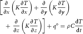
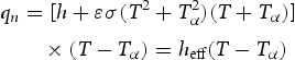
For the evaluation of realistic temperature history, heat loss to the surrounding was taken into account by considering radiation and convection losses. The combined radiation and convection loss from the material to surrounding is given in Equations (2)–(3), respectively:

In case of mechanical analysis, the elastic strain component was modelled using isotropic Hook's law with temperature-dependent Young's modulus and Poisson's ratio. The plastic behaviour was assessed with Von-Misses criterion, temperature-dependent mechanical properties and isotropic hardening model. To calculate the thermo-metallurgical strain, strains that arise due to temperature-dependent thermal expansion co-efficient as well as phase changes i.e. volumetric change associated with martensite to austenite (volumetric contraction) and austenite to martensite (volumetric expansion) were included. During fusion welding, high temperature thermal cycle is for very short period so creep behaviour of material was neglected and hence, the total strain was equated as in Equation (4)

The assumptions made and the basic model considered are same as those used for predicting residual stress and distortion in modified 9Cr–1Mo steel welds in a recent study [9].
Results and discussion
Implant test data and corresponding diffusible hydrogen content of the weld.
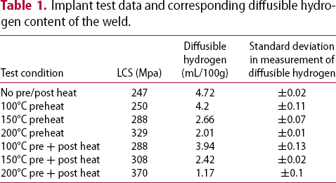
Diffusible hydrogen content of the electrode, i.e. for the weld prepared without any preheat and post heat and diffusible hydrogen measurement carried out without allowing any hydrogen to diffuse out before measurement is 4.72 mL/100 g. The time taken by the implant specimen and diffusible hydrogen measurement sample to cool to 100°C is 9.5, 13, 14.8, 16 min and 10, 13.5, 15.6, 16.7 min respectively for welding without any preheat and 100°C, 150°C, 200°C preheating conditions. Hence, the cooling time taken by the implant specimens and the diffusible hydrogen measurement specimens are nearly the same for a particular preheat condition. Although, the sample size and geometry are different in these two test methods, diffusible hydrogen remaining in the weld can be assumed to be the same, under identical cooling conditions. It is clear that diffusible hydrogen content of the weld comes down with application of preheat (2.01 mL/100 g for 200°C preheat) and it further reduces with application of post heating. For sample welded with 200°C pre + post heating, the diffusible hydrogen content is appreciable low i.e. 1.17 mL/100 g. The accuracy of measurement of diffusible hydrogen was ascertained in all the tests and the standard deviation of measurement is within two decimals in all the cases.
Implant test is considered as an externally restraint test; but the thermal cycle associated with bead on plate weld made for the test can generate residual stress in the weld and the combined external stress and the residual stress present in the weld act on the specimen during the testing. It is clear that the LCS value of the implant specimen increases with increasing preheat temperature. Application of post heating along with preheat further improves the LCS value and reduces the cracking severity of the weld. Preheating decreases the cooling rate of the solidified weld pool thereby, allowing more time for the hydrogen to diffuse out, which contributes to lower cracking tendency of the weld. The objective of post heating the sample in addition to preheating is to provide more time for hydrogen diffusion. Some recent studies on P91 steel weld have indicated that post heating is helpful in lowering down the peak tensile residual stress of the weld joint [9]. This contributes to the lower cracking tendency of the weld and LCS determined for 200°C pre and post heating is significantly high. It is also evidenced from the results that post heating is much effective than preheating in lowering down the cracking susceptibility of the weld. We have observed in our earlier studies that in G-BOP test of P91 weld, 200°C pre and post heating is required to get crack free weld, whereas while testing HAC susceptibility of P91 weld by Y-groove test, no crack is detected with 100°C pre and post heating [10]. Thus, preheating and post heating estimated to avoid HAC is higher for G-BOP test than for Y-groove test. Y-groove test is a self restraint test and G-BOP test has a component of external restraint, in the form of clamping. The preheat and post heating condition to prevent fracture of the implant test specimen during 24 h of testing is same as that of G-BOP test. This indicates that external restraint tests require high preheat and post heat temperatures to avoid HAC than the self restraint tests.
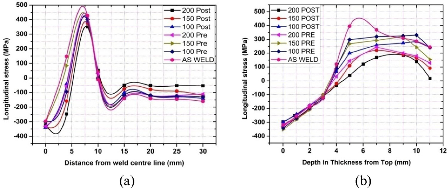
One probable reason for the apparent difference in the susceptibility to HAC estimated from a self restraint test (Y-groove test) and from external restraint tests (G-BOP and implant tests) could be due to the role of residual stress generated during welding which is neglected in the external restraint tests. Thus, to understand the nature of the residual stresses generated during welding, FEM based thermo-mechanical modelling of bead-on-plate welding was performed and the typical results of the computational analysis are presented in Figure 2. It may be noted that stresses are compressive in nature at the weld centre and tensile, away from it. Figure 3(a) shows the computed longitudinal stress distribution from weld centre to one side of the baseplate for different pre/post heating condition. It can be seen from Figure 3(a) that up to 5 mm distance from the weld centre line, the residual stress is compressive in nature and away from that the stress is tensile. The peak of the tensile residual stress for the bead-on-plate weld made without any pre/post heating is at 7.2 mm from weld centre line, which is close to the fusion boundary. The magnitude of the peak tensile residual stress is quite high here ∼490 MPa. For specimens prepared with preheating the magnitude of residual stress comes down and it further decreases with application of post heating. The peak value estimated is 350 Mpa at 7.6 mm from the weld centre line for a combined preheating and post heating at 200°C. It can be further noted from Figure 3(a) that with application of preheating and post heating the location of peak stress gradually shifts from fusion boundary towards the HAZ. Similarly, the distribution of the residual stresses along the length of the implant specimen is plotted in Figure 3(b) and this indicates that the peak value of residual stress is 450 MPa at 5.5 mm from top surface for welding without preheating the plate. This value is reduced up to 146 MPa for welding with combined preheating and post heating at 200°C and the location of peak tensile stress value shifted away from the top of the bead towards the HAZ. Thus, residual tensile stress of sufficiently high magnitude is present in the sample welded without any pre or post heating. During loading of the implant specimen for testing, this residual stress gets re-distributed. Hence, the actual load experienced by the weld would be different from that actually recorded in the load cell. This could be the possible reasons for higher preheat and post heat temperature estimated to avoid HAC for G-BOP test and implant test of present study than that of Y-groove test for the same material [10]. Presence of diffusible hydrogen further aggravates the cracking severity. With application of pre and pre + post heating the diffusible hydrogen content comes down so as the magnitude of the tensile residual stress. Hence, the cracking susceptibility of the weld lowers down and the specimen does not fail even at a higher applied load. It is to be noted here that although the sample geometry, dimensions for implant testing and that of diffusible hydrogen measurement is different, the welding parameters and cooling rate being same for both the test specimen, it can be very well presumed that cracking susceptibility of the samples due to HAC is the same and the predominant cause for implant sample to fail is HAC and not due to the applied tensile deformation.
FEM simulation for longitudinal stress distribution in bead on plate welding. Stress distribution in (a) transverse and (b) thickness direction of bead-on-plate weld.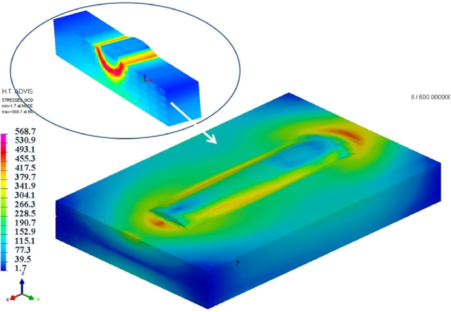
It is evidenced from the above discussion that presence of diffusible hydrogen in the weld, high tensile stresses developed from the applied load and residual stresses generated from the specimen geometry, weld thermal cycle are the key factors to cause HAC. However, the untempered martensitic microstructure of the weld and HAZ of high hardness (average microhardness of weld and HAZ is 450 and 375 VHN respectively) also contribute to the higher cracking susceptibility of the P91 weld. Although, AWSE9018-B9 electrode belongs to low hydrogen category as per IIW specifications, the HAC susceptibility of P91 steel weld is fairly high due to its martensitic microstructure.
Examination of the failed implant samples reveals that cracking is initiated from the helical notch (HAZ area) of the implant specimen and for high load condition (short duration for fracture) the crack has propagated through the weld whereas for low load condition (long duration for fracture) the crack propagates through HAZ (Figure 4). During welding the hydrogen is introduced in the sample through the weld. At higher applied load, the critical concentration of hydrogen at notch tip for crack to initiate is low and time to fracture is less. In this condition, the concentration of hydrogen in the weld would be more as the time available for diffusion of hydrogen to HAZ is less. Thus, crack propagates through the weld. At lower applied load, the time required for the hydrogen concentration to reach the critical value to initiate crack at the notch tip is high and during this time hydrogen would have also diffused into HAZ. Hence, the concentration of hydrogen in HAZ is more causing crack propagation through HAZ [2].
Microstructure of implant sample welded with 150OC preheat and tested at 1500 kg load.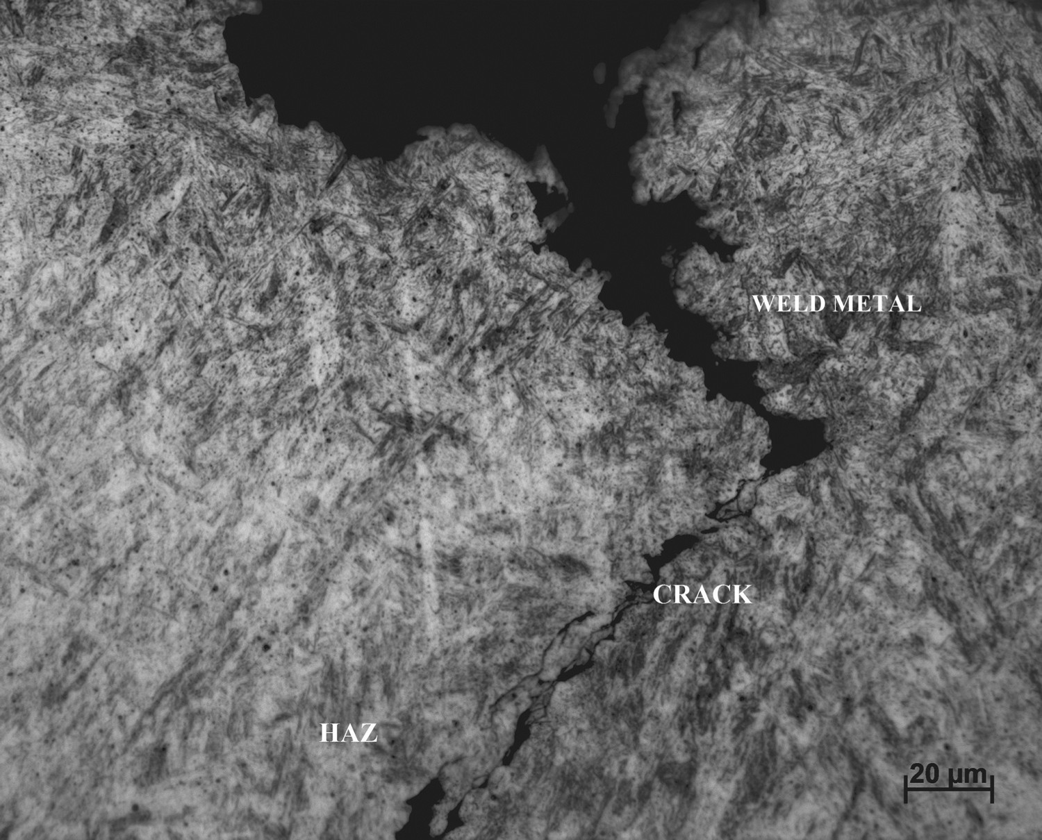
The objective of the present study is to assess the HAC susceptibility of P91 steel weld and to bring together the effect of all the contributing factors to HAC of P91 weld i.e. diffusible hydrogen, microstructure of the weld, residual and applied stress to the weld. It clearly shows the effect of preheating and post heating in bringing down not only the diffusible hydrogen content but also peak tensile residual stress in the weld. Further, the study reveals that even for bead-on-plate welds, the peak tensile residual stress can be quite high and can affect the results obtained from various cracking tests. The study recommends 200°C as the required pre/post heating temperature of P91 steel to get a crack free weld. Thus, the study not only correlates all independent factors i.e. microstructure, diffusible hydrogen content and residual stresses present in the weld contributing to HAC, it also recommends a solution for the HAC problem of the ferritic weld.
Conclusions
The study illustrates the effect of all the contributing factors to HAC of P91 weld i.e. diffusible hydrogen, microstructure, residual and applied stress to the weld. The peak tensile residual stresses even for a bead-on-plate weld can be quite high and this can contribute to cracking along with external loading. A combination of preheat and post heating, in addition to allowing diffusion of hydrogen from the weld, can bring down the peak tensile residual stresses significantly and lowers down the risk of cracking. The results propose 200°C as the optimum temperature for preheating and post heating required to prevent HAC during P91 steel fabrication.
Footnotes
Disclosure statement
There is no potential conflict of interest in this research work.