
Abstract
In this study, the influence of the microstructural evolution of galvannealed (GA) coating and the thermomechanical characteristics of liquid metal embrittlement (LME) cracking during resistance spot welding (RSW) of steels were investigated. The analysis of LME cracks, coating microstructure and thermomechanical characteristics at various weld regions revealed a synergistic effect of liquid Zn, α-Fe(Zn), and tensile stress on LME cracking during RSW. A continuous α-Fe(Zn) layer inhibits liquid Zn from contacting the steel substrate; hence, LME was suppressed. However, a long-duration, high-magnitude tensile stress can fragment the α-Fe(Zn) layer and enable LME cracking. Conversely, α-Fe(Zn) particles allow the easy infiltration of liquid into the steel and make the crack on tensile stress development.
Keywords
Introduction
Over the past two decades, the use of advanced high-strength steels (AHSSs) in the automobile industry has increased in order to satisfy the strict regulations on CO2 emission, enhanced fuel efficiency standards and passenger safety [1]. Compared with conventional steels, AHSS reduces car body sheet thickness, while satisfying the strength and formability requirements. To prevent corrosion, AHSSs are typically coated with zinc (Zn) or aluminium (Al) [2, 3]. Generally, Zn coatings are available in two types: galvanised (GI) and galvannealed (GA). GI consists of pure Zn and a thin Fe2Al5 inhibition layer and is produced by hot-dipping the steel into a molten Zn–Al bath, whereas GA is produced through the post-dip heat treatment of a non-Al-containing Zn coating at temperatures ranging from 450 to 590 °C. Heat treatment enables the diffusion of iron (Fe) into the coating, and Fe–Zn intermetallic compounds are consequently formed in the GA coating [2].
In the automobile industry, resistance spot welding (RSW) is a fusion welding process that is used to assemble steel sheets; in this process, the heat required for melting is produced by passing high current through copper electrodes [4-6]. However, Zn coating is prone to liquid metal embrittlement (LME) cracking during RSW [7-11]. Furthermore, Zn-assisted LME cracking entails the penetration of liquid Zn (Znliq.) into the steel microstructure through the grain boundaries under tensile stress, thereby causing grain boundary decohesion and cracking in the steel [12-14]. These cracks potentially affect the mechanical behaviour of the welds and therefore need to be controlled [15].
Various studies have been conducted to understand the influence of different factors, such as the steel microstructure [9, 16], welding electrode [10, 17, 18] and welding parameters [19, 20], on LME during RSW. However, the effect of Fe–Zn reaction and the resulting microstructural evolution of Zn coating have not been sufficiently studied. Lee et al. investigated the influence of the microstructural evolution of GI coatings and the influence on LME cracking during RSW and found that the presence of α-Fe(Zn) particles in the coating/steel interface enhanced LME cracking [21]. Hong et al. studied the influence of Si on the GI coating microstructure and LME cracking in RSW [22] and revealed that a high Si content retarded the formation of α-Fe(Zn), which in turn resulted in higher LME sensitivity outcomes owing to a high Znliq. contact with the steel. These contradicting claims necessitate a systematic investigation of the effect of Zn coating microstructures on LME cracking considering all the thermal, mechanical and metallurgical phenomena in each weld location during welding. Moreover, there have been no reports on studies related to the microstructural evolution of GA coating and their effects on LME cracking during RSW, regardless of the fact that the chemistry and microstructure of GA coatings differ from those of GIs.
In our previous work, it has been found that LME sensitivity is strongly influenced by the microstructural evolution (thermodynamics and kinetics of Fe–Zn reaction) of GA coating using hot tensile test [23]. This work is an extension of our previous research and aims to investigate the effect of microstructural evolution of GA coating on LME cracking in RSW by considering the thermal, mechanical and metallurgical phenomena at each weld locations.
Experimental procedure
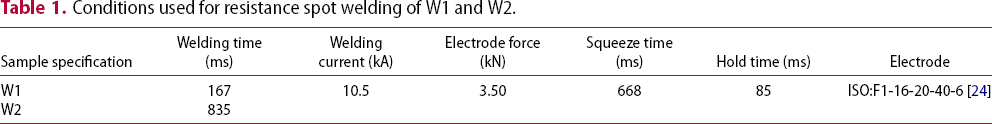
Conditions used for resistance spot welding of W1 and W2.
The dynamism of the thermomechanics during RSW complicates the analysis of the microstructural evolution of Zn coatings. Therefore, heat treatment using the Gleeble simulator was used to physically simulate the thermal cycle of RSW by various researchers to understand the Fe–Zn reaction [22, 23]. The peak temperatures of the heat treatment were 600, 700 and 800 °C, which were determined by considering the temperature history of the real RSW and the invariable reactions in Fe–Zn phase diagram. The LME cracks and the microstructure of the coating and steel were analysed via optical and scanning electron microscopy (SEM) after proper metallographic sample preparations [23]. During SEM, backscattered electron (BSE) mode and energy-dispersive X-ray spectroscopy (EDS) were used to identify various phases in the coating. Moreover, electron backscattered diffraction (EBSD) was employed to investigate the grain boundary characteristic distribution of the coating. To understand the thermal and mechanical characteristics during RSW, the commercial simulation software SORPAS® was used [11].
Results
LME cracks in welds
Previous studies have found the temperature and stress distribution, and consequently, the LME cracking behaviour varies depending on the location of the electrode/sheet (E/S) interface [11, 20]. Therefore, an attempt was made to separate the locations of the E/S interface into various regions according to the contact behaviour between the electrode and the sheet, as presented in Figure 1(a–d). As can be seen, two circular borders and three regions are observed: border 1 (B1) divides the initial contact (Ic) and transient contact (Tc) regions, while border 2 (B2) divides the Tc and non-contact (Nc) regions, as shown in Figure 1(a–d). Ic represents the E/S contact zone during the squeeze time. The uniform contact with the water-cooled electrode through the welding time induced a low-temperature Ic region. Notably, the Tc is the one in which the electrode comes in contact with the sheet during the welding time, i.e. the circle of contact of the E/S moved from B1 to B2 as illustrated by the solid red arrows in Figure 1(a,c), and led to the creation of the Tc region [11]. Dynamic heating and cooling can be expected to occur in this region as the circle of contact begins to move rapidly. Additionally, the Nc lies just outside of the E/S contact area, which never contacts the electrode during the welding time; thus, it experiences a continuous increase in temperature until the welding is completed [11]. Both W1 and W2 exhibited the same Ic radius as the electrode forces and squeeze times were the same. However, the Tc radius of W2 was higher than that of W1 owing to the extended welding time of the former.
Various regions of LME cracks in welds W1 (a,b) and W2 (c,d): optical image of the surface (a,c) and cross-section (b, d) of the welds. LME cracks in various regions in weld W1 (e) and W2 (f,g).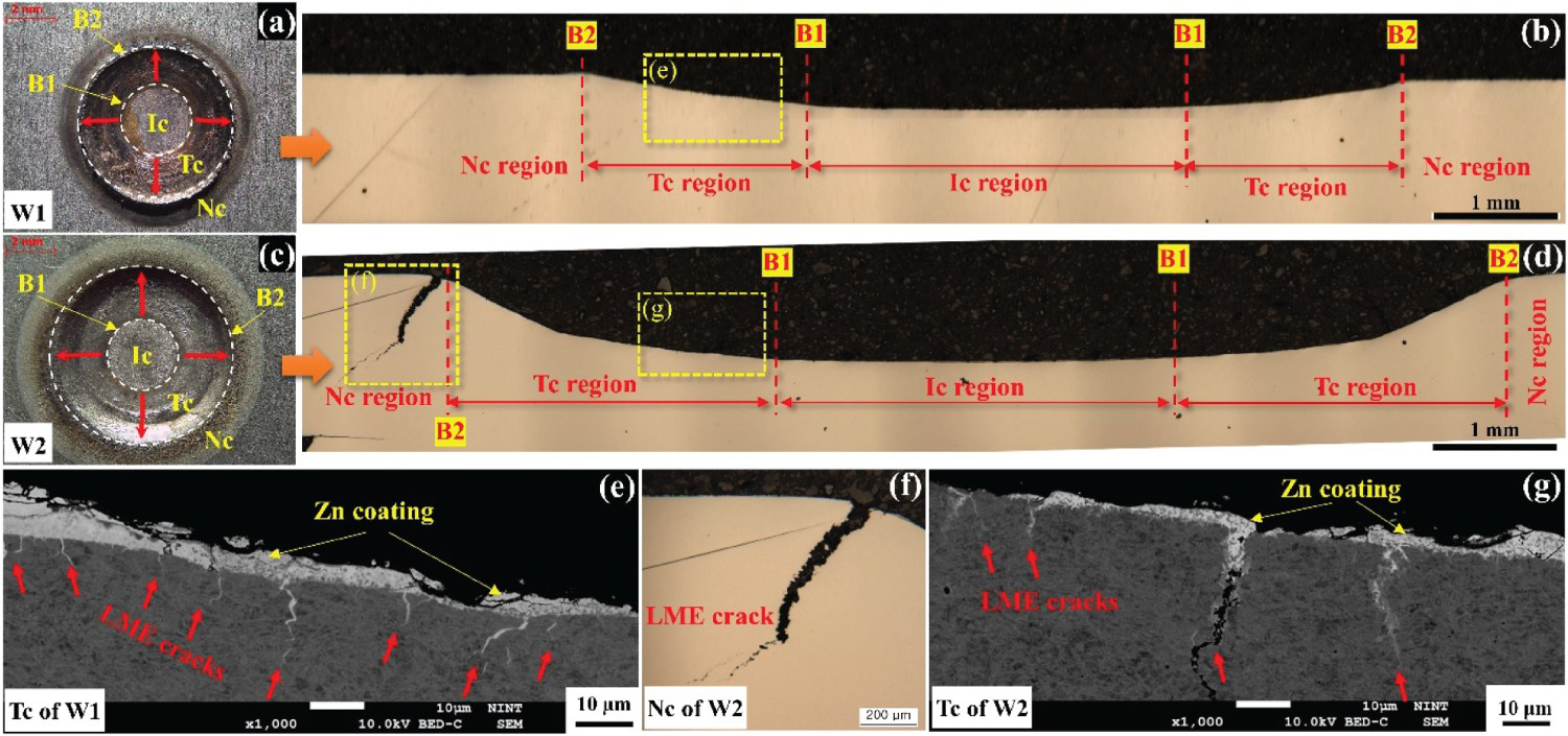
Figure 1(e–g) shows the LME cracks in various regions of the welds (arrows). Generally, the maximum crack length (MCL) and the number of cracks are used to indicate the LME sensitivity of each weld region. However, the number of cracks is influenced by the cutting direction. Therefore, in this study, the MCL was measured to deduce the LME sensitivity of each weld region. No cracks were observed in the Ic of both the welds, whereas the Tc of the two welds exhibited several LME cracks with lengths in the order of micrometres. The MCLs were 19 and 55 μm for the Tc values of W1 and W2, respectively. No cracks were found in the Nc region of W1; however, a large LME crack, with a length of 814 μm, was observed in that of W2. It is evident that the regions and welding time significantly impacted the cracking lengthwise. Therefore, it can be concluded that the E/S contact significantly influences LME cracking during RSW. These observations are consistent with the findings reported in previous studies [11, 20]; therefore, an attempt to investigate the role of Zn coatings on LME behaviour, as mentioned above, which has not been the focus of previous studies, is presented herein.
Temperature distribution is an important factor for determining LME cracking in RSW; this can be inferred from the microstructure of the weldments, especially from the perspective of the fusion zone and heat-affected zone (HAZ) [7, 17]. It is evident from the nugget diameter and HAZ width in Figure 2(a–b) that the heat input in W2 is higher than that in W1. A thin intercritical HAZ (ICHAZ) was formed near the shoulder region of the E/S interface in W1, whereas a thick ICHAZ was formed away from the shoulder region of the E/S interface in W2. Notably, based on Joule's law of heating, heat input increases with weld time.
Nugget diameter, fusion zone and heat-affected zone in welds W1 (a) and W2 (b).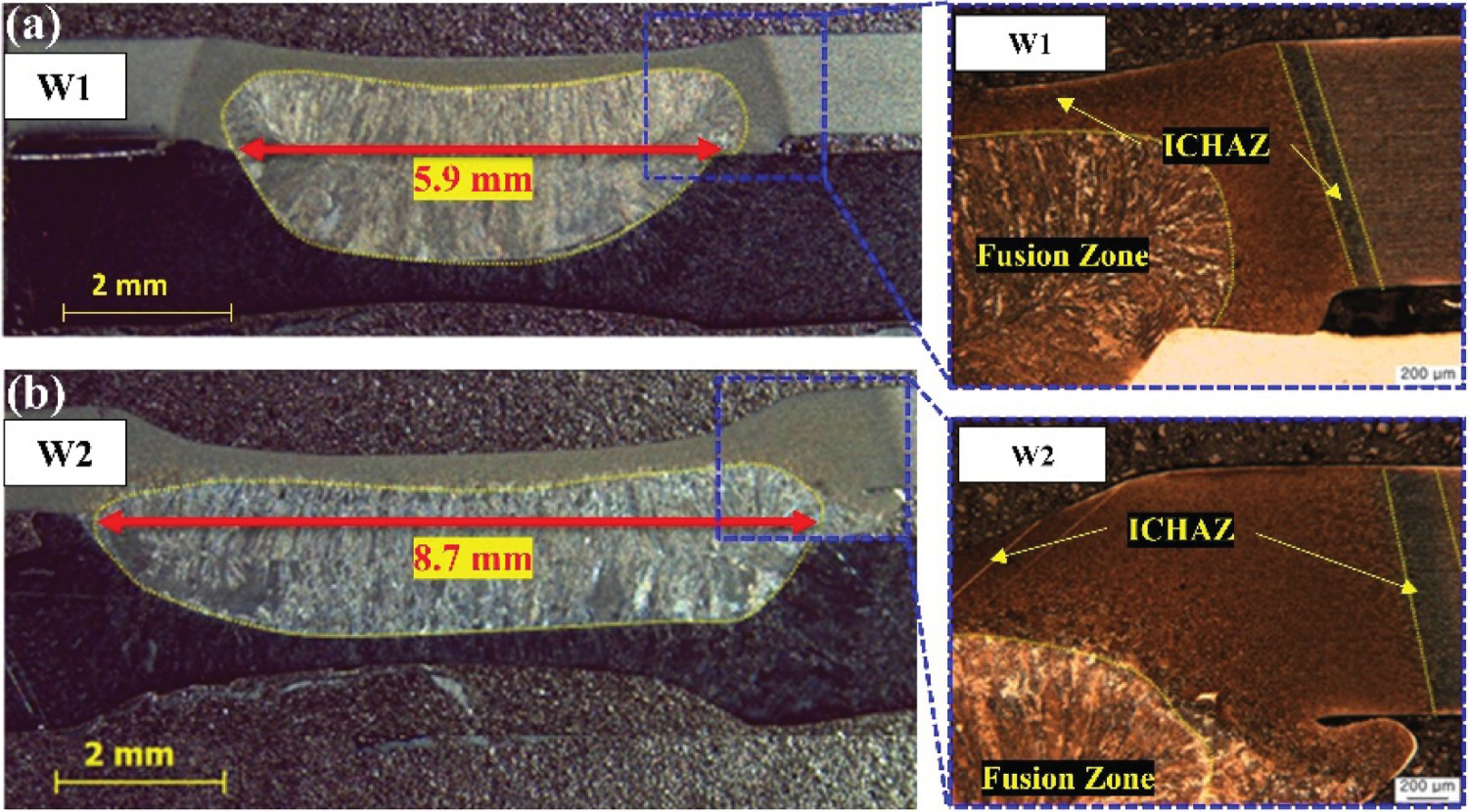
Microstructure of coating
Resistance spot welding
Figure 3(a–g) shows the BSE images of initial and post-weld microstructure of the GA coating. The phases are identified using the contrast difference in the BSE image, EDS elemental analysis and the simulated Fe–Zn phase diagram [23]. The initial GA coating consisted of a thick layer of δ (4.9 µm) and a thin layer of Γ (1.2 µm), as shown in Figure 3(a). The post-weld coating consisted of various phases based on the condition and region of the weld. Additionally, the thickness of the coating changed after the welding, and it was also varied based on the condition and region in the weld, as listed in Table 2.
Microstructure of the coating characterised using BSE mode in SEM: as-received GA coating (a); various weld locations after RSW (W1 (b–d) and W2 (e–g)). EDS line analysis of as-received GA coating (h) and Nc of W1 (i). The corresponding EDS lines are shown in (a) and (d). Thickness of the coating in base metal and various regions of the weld surface measured from the BSE-SEM images (Figure 3).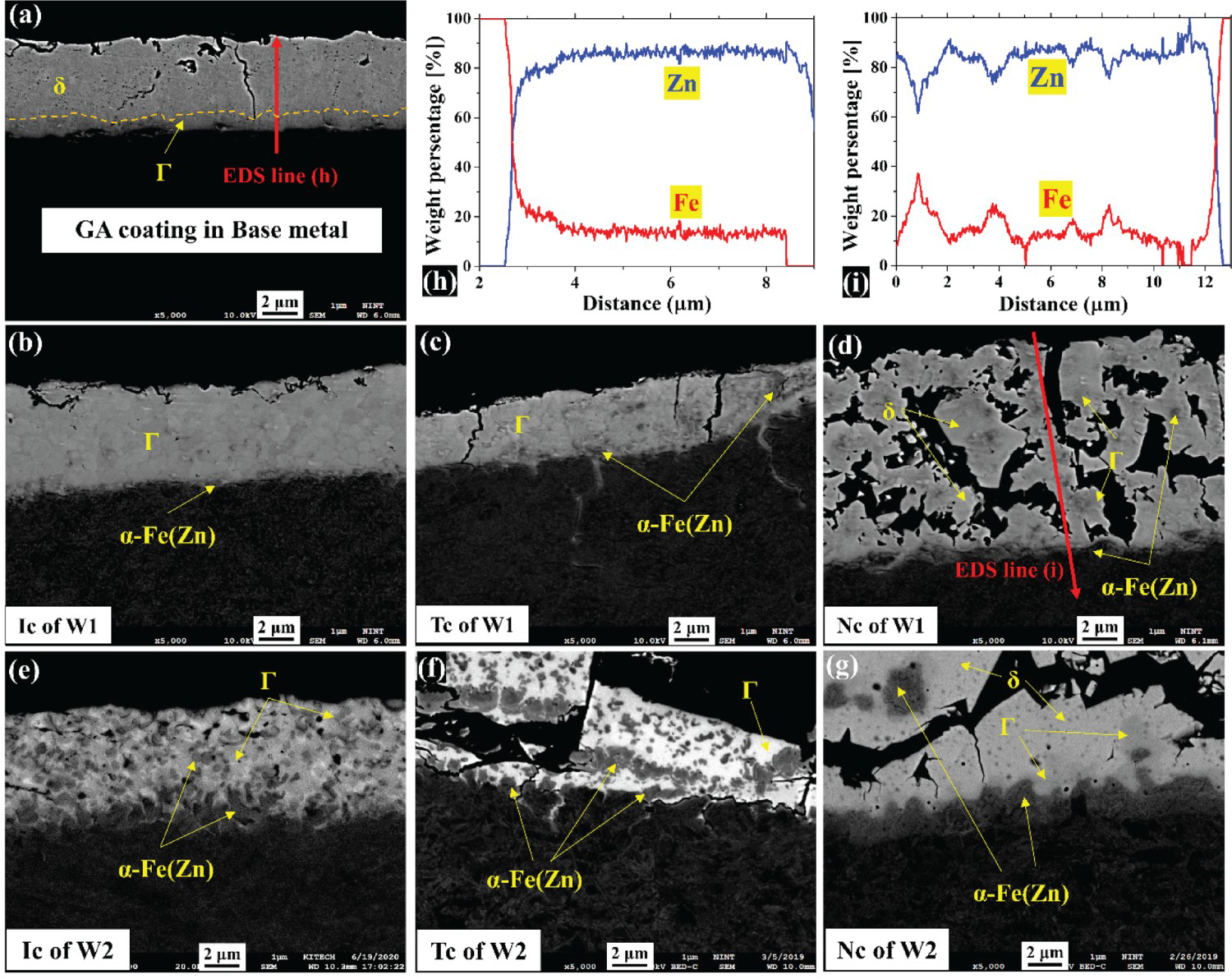
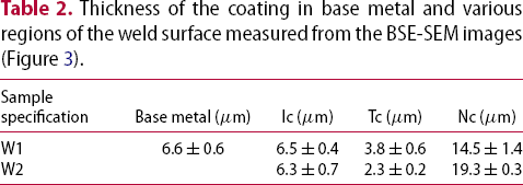
The post-weld coating in Ic of W1 (Figure 3(b)) and W2 (Figure 3(e)) consisted of Γ and α-Fe(Zn) particles; however, the fraction and distribution of α-Fe(Zn) was higher in W2. The thickness of the post-weld coating in Ic did not vary significantly between W1 and W2 (Table 2). The coating in the Tc of W1 (Figure 3(c)) and W2 (Figure 3(f)) also consisted of Γ and α-Fe(Zn) particles, while the fraction and distribution of α-Fe(Zn) in the coating of Tc was higher in W2 than in W1. In addition, the total thickness of the coating significantly decreased. The Nc region of W1 (Figure 3(d)) and W2 (Figure 3(g)) consisted of a thick coating with δ, Γ and α-Fe(Zn) as the major phases. Compared with the other regions, Nc exhibited a thick and uniform α-Fe(Zn) layer along with α-Fe(Zn) particles. The post-weld coating in the Nc region retained the δ phase in W2 with an extended welding time, and the thickness of the coating was higher than that of the initial one, as shown in Figure 3(g).
From the observations of the post-weld coating at various locations, it is evident that various thermal (heating and cooling), mechanical (evolution of E/S contact) and metallurgical (Fe–Zn reaction) phenomena occur in the coating during RSW. To study the metallurgical phenomena with the thermal cycle of welding, heat treatment was performed using a Gleeble for simulating the RSW.
Heat treatment
The SEM images of the coating after heat treatment are shown in Figure 4(a–c). At 600 °C, the coating was composed of a thick layer of δ, a thin layer of Γ and a few fine particles of α-Fe(Zn). The coating did not undergo any major metallurgical transformation except for the formation of fine α-Fe(Zn) particles. At 700 °C, the coating consisted of a thick Γ layer with dispersed δ islands and a thin α-Fe(Zn) layer. This indicated that a substantial amount of Fe–Zn reactions occurred at 700 °C, and consequently, the coating was significantly transformed relative to the initial GA coating. At 800 °C, the GA coating transformed into an Fe–Zn coating with layers and islands of δ and Γ, as well as a thick α-Fe(Zn) layer. From Figure 4, we can summarise that the temperature increased with the phase fraction of α-Fe(Zn). Moreover, α-Fe(Zn) transformed from a particle to a continuous layer when the temperature increased from 600 to 700 °C, and thereafter, the layer got thicker with a further increase in temperature.
Microstructure of the coating after heat treatment at 600 °C (a), 700 °C (b) and 800 °C (c) characterised using BSE mode in SEM.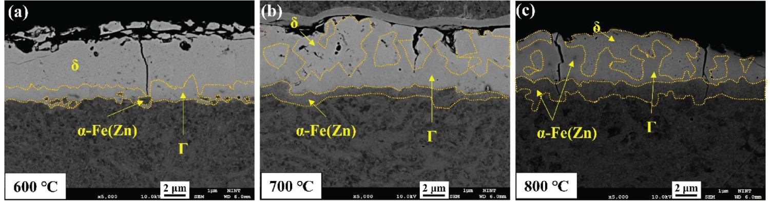
Thermal mechanical characteristics of welding
Temperature and tensile stress are the key factors that lead to LME cracking during RSW; hence, these factors must be considered with respect to various regions of the welds [11, 20]. The history of temperature and stress in various regions obtained from SORPAS® simulation are depicted in Figure 5(a–d). As can be seen from the temperature plot of W1, the Tc and Nc regions experienced a relatively higher temperature than that of the Ic. Furthermore, the Ic and Nc regions experienced the peak temperature at the end of the welding time, whereas that of the Tc experienced the peak temperature within the welding time, as illustrated in Figure 5(a). A similar trend in the temperature history is observable in W2, whereas a higher welding time than W1 resulted in a higher peak temperature in the Ic region than that of W1. However, all the regions experienced the same off-time peak temperature, as presented in Figure 5(b). Similarly, different stress histories were observed among the various regions of the welds, as depicted in Figure 5(c,d). The Tc and Nc regions of the welds experienced tensile stress at the beginning and end of the weld time, respectively. Conversely, the Ic region of W1 did not undergo tensile stress, whereas in W2, it experienced tensile stress towards the end of the weld time and the beginning of the hold time. Previously, we established that the nature of electrode–sheet contact determines the difference in the stress history among the various weld regions [11]. Contact with the electrode caused a lower temperature in the Ic region. However, the Tc and Nc regions were not in contact with the electrode, which resulted in a continuous temperature increase. However, the Tc region experienced a sudden temperature drop within the welding time as it touched the electrode owing to the movement of the E/S contact. The tensile stress developed in the Tc and Nc regions is primarily thermally activated as they are induced by the non-linear temperature gradient at the edge of the E/S contact, owing to the sudden temperature drop caused by the movement of the thermal contact between the E/S [10, 11].
The simulated temperature (a,c) and stress (b,d) at various regions of welds W1 and W2, respectively, obtained using SORPAS®.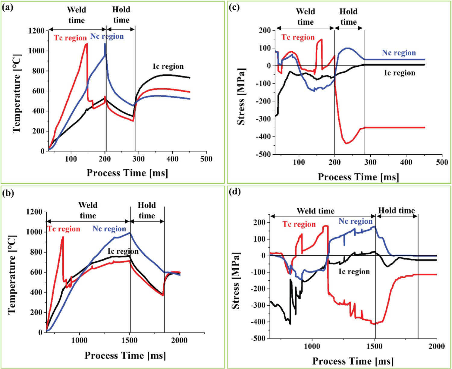
Discussion
Microstructural evolution of GA coating during welding
Notably, Zn-induced LME cracking is strongly related to the Fe–Zn reaction and the phase composition in the coating, especially, the amount of Znliq. and α-Fe(Zn) [21-23, 25]. Therefore, the microstructural evolution of Zn coatings must be examined during RSW. First, the microstructural evolution of the GA coating during heat treatment was investigated, as illustrated in Figure 6, and it was thereafter applied to the microstructural evolution of the coating during the RSW process.
Microstructural evolution of GA coating during heat treatment with different temperatures explained using the Fe–Zn phase diagram.

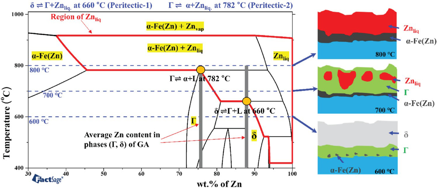
During heat treatment, the GA coating was heated to 600 °C, whereas δ and Γ were maintained at a stable rate without the formation of Znliq., according to the Fe–Zn phase diagram presented in Figure 6 [23]. The diffusion of Fe into Zn caused the isothermal phase transformation of δ to Γ, thereby resulting in an increase in Γ and a decrease in δ. In addition, a few α-Fe(Zn) particles were precipitated as a result of this diffusion, as illustrated in the schematic in Figure 6, and then, the coating turned into δ and Γ layers, as well as a few α-Fe(Zn) particles after cooling, as presented in Figure 4(a). At 700 °C, the initial coating transformed into Znliq. and Γ due to the peritectic reaction (equation (1)). Thereafter, Znliq. experienced isothermal solidification to form Γ, and an α-Fe(Zn) layer was formed due to Fe–Zn interdiffusion at the steel/Γ interface [23]. The remaining Znliq. transformed back to δ during cooling due to the peritectic reaction (equation (1)); hence, the coating at room temperature consisted of δ, Γ and α-Fe(Zn) layers, as shown in Figure 4(b). The initial GA coating transformed into Znliq, following equation (2) and α-Fe(Zn) when heated to 800 °C owing to the two peritectic reactions (equations (1) and (2)) and the interdiffusion of Fe and Zn, as presented in Figure 6. Meanwhile, due to the isothermal solidification of Znliq., the α-Fe(Zn) layer thickness increased to α-Fe(Zn) during isothermal holding at 800 °C [23]. The remaining Znliq. transformed to δ and Γ during cooling (equations (1) and (2)); hence, the coating at room temperature consisted of δ, Γ and α-Fe(Zn) layers, as described in Figure 4(c).
Based on the understanding of the Fe–Zn reactions and microstructural evolution during heat treatment, as well as the thermomechanical phenomena that take place during RSW, changes in coating during RSW can be elucidated as follows:
During RSW, the initial GA coating with δ and Γ transformed into Znliq. and Γ in the Ic region, after undergoing the peritectic reaction (equation (1)), as depicted in Figure 6, as the peak temperature of the region was approximately 750 °C. Simultaneously, Znliq. transformed to Γ owing to the Fe–Zn interdiffusion-induced isothermal solidification. In addition, α-Fe(Zn) particles were formed due to the Fe–Zn interdiffusion at the steel/Γ interface. The fraction of the α-Fe(Zn) particles was greater in W2 than in W1 owing to the extended welding time of W2; this led to additional Fe–Zn interdiffusion. However, the actual welding time was less than that in the case of heat treatment; this resulted in less Zn diffusion into Fe to form an α-Fe(Zn) layer during welding.
Furthermore, the Tc region experienced a relatively high peak temperature (∼1000 °C), thereby inducing the transformation of the initial δ and Γ into Znliq., as well as α-Fe(Zn) after the two peritectic reactions (equations (1) and (2)), as displayed in Figure 6. Thereafter, this region experiences a sudden contact with the electrode due to the E/S contact, which provides a sudden cooling, as illustrated in Figure 5(a,b), thereby resulting in the solidification of the remaining Znliq. to Γ and α-Fe(Zn) with a lower coating thickness, as shown in Figure 3(c,f) and Table 2.
Notably, the Nc region did not contact the electrode; hence, the temperature continued to increase and reached a peak value of approximately 1000 °C during the welding time, resulting in the transformation of the initial coating into Znliq. and α-Fe(Zn), as shown in Figure 6. However, the mechanical squeeze of the Znliq. from the Tc zone fed this region with more Znliq. This is evident from the post-weld coating thickness (Table 2). The excess Znliq. with a higher Zn content solidified into δ and Γ. The higher temperature and weld time enabled additional Fe–Zn interdiffusion, resulting in the formation of a thick and continuous α-Fe(Zn) layer in this region, as shown in Figure 3(d,g).
Influence of coating microstructure and tensile stress on LME cracking
As shown in Figures 1 and 7, LME cracks were found only in the Tc region of W1, as well as in those of the Tc and Nc of W2. As presented in Figure 7(a,c,d), LME cracks are formed with either discontinuous α-Fe (Zn) particles or a fragmented α-Fe(Zn) layer, such that the Znliq. and the steel surface are in direct contact. These results are consistent with those reported by Lee et al. [18].
Correlating the coating microstructure and LME cracking at different regions of the welds: Tc of W1 (a); Nc of W1 (b); Tc of W2 (c) and Nc of W2 (d).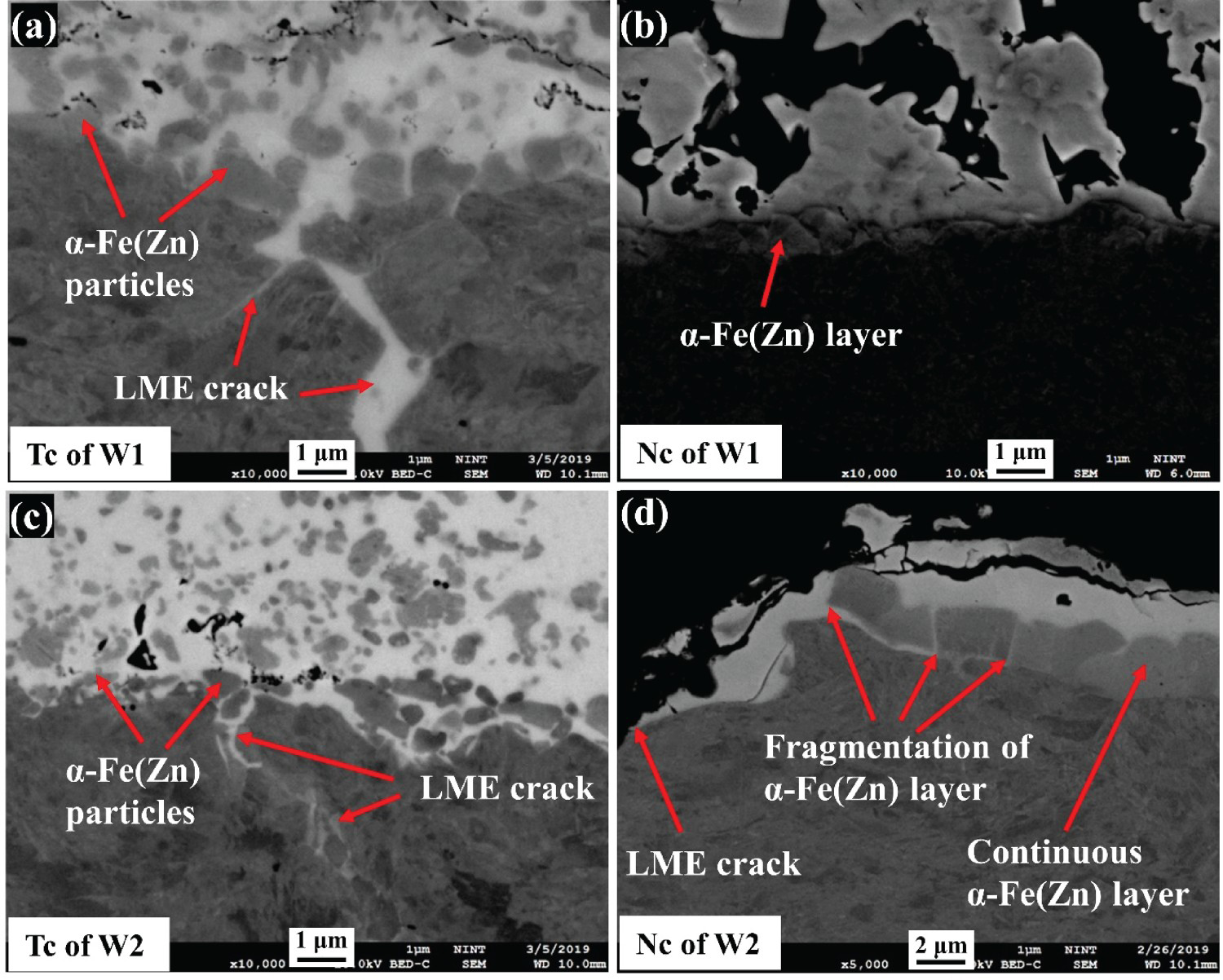
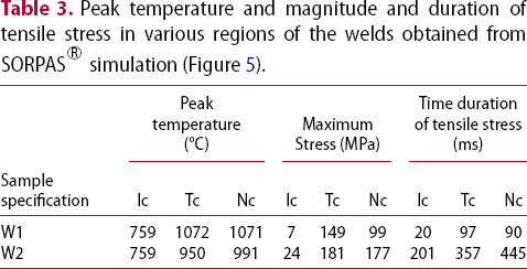
In the Ic region of W1 and W2, Znliq. was unavailable, and the magnitude of tensile stress was negligible during crack development (Table 3). In the Tc region of W1 and W2, a significant amount of Znliq. was available, which easily infiltrated the discontinuous α-Fe(Zn) particles and caused LME cracking when the tensile stress was developed. However, the crack length was less in the Tc region as the duration of tensile stress at high temperatures was relatively less in this zone owing to the continuous movement of the electrode contact to the sheet surface. Although a surplus amount of Znliq. and tensile stress was present in the Nc region of W1 and W2 (Table 3), LME cracks at the Nc region were only formed in the W2 samples. However, no fragmentation of the α-Fe(Zn) layer was found in the Nc region of W1, as evident in Figure 7(b). However, the continuous layer in the Nc region of W2 was fragmented by the induction of long-duration and high-magnitude tensile stress. The continuous α-Fe(Zn) layer consisting of several high-angle grain boundaries were oriented perpendicular to the direction of the tensile stress, as shown in Figure 8. Generally, random high-angle grain boundaries are weaker at elevated temperatures; this results in the fragmentation of the α-Fe(Zn) layer based on the induction of high-magnitude tensile stress for a long duration [14, 26].
High-angle boundary (HAB) with misorientation 5–50° in α-Fe(Zn) layer characterised using EBSD. Peak temperature and magnitude and duration of tensile stress in various regions of the welds obtained from SORPAS® simulation (Figure 5).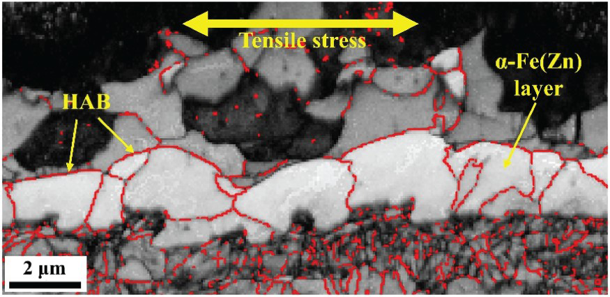
Based on the aforementioned discussions, the synergistic effect of Znliq., α-Fe(Zn), and tensile stress is concisely illustrated in the schematic presented in Figure 9. Tensile stress, as well as the contact between Znliq. and substrate steel, are necessary conditions for LME cracking. If α-Fe(Zn) forms as particles, then the Znliq. easily contacts the steel and forms cracks during the development of tensile stress. If α-Fe(Zn) is formed as a continuous layer, the Znliq. is inhibited from contacting the steel; thus, LME cracking is suppressed. However, if a high-magnitude tensile stress is induced for a long duration, the α-Fe(Zn) layer undergoes fragmentation to allow the contact between Znliq. and steel, consequently leading to LME cracking.
Schematic representation of the synergistic effect of liquid Zn, α-Fe(Zn) and tensile stress on LME cracking in RSW.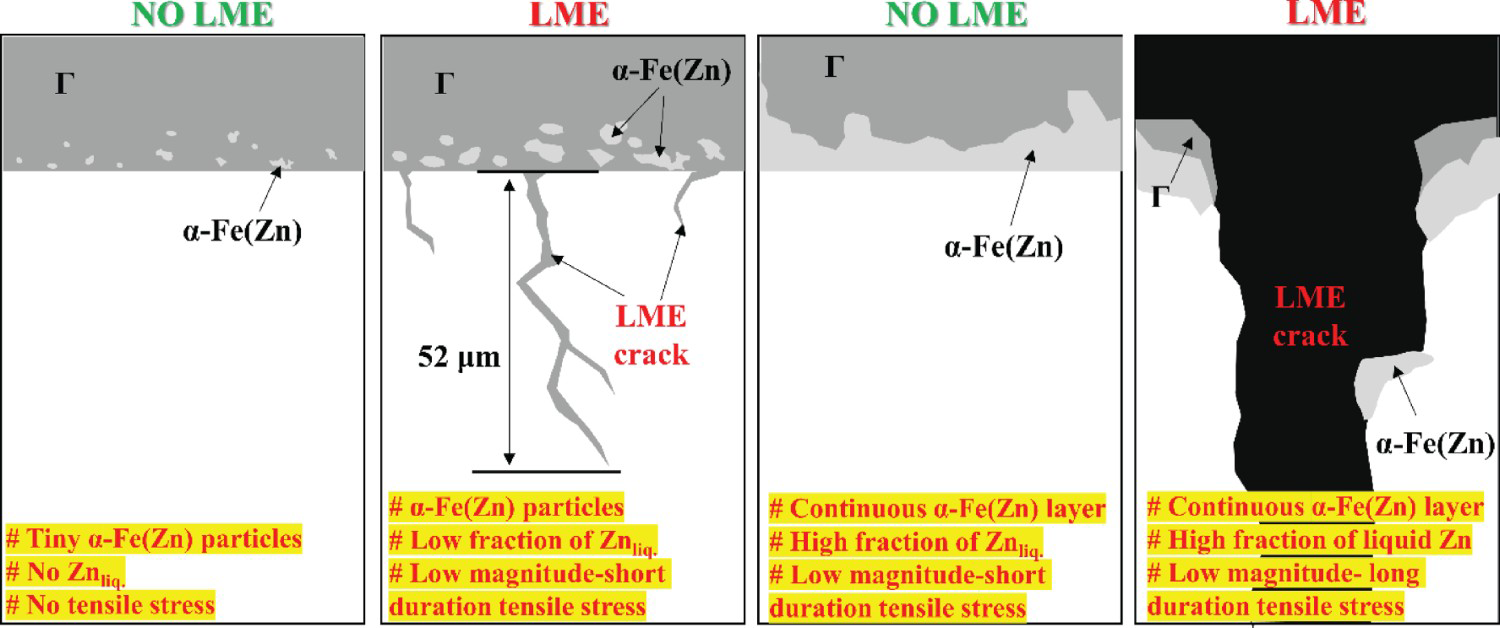
Conclusion
The effect of microstructural evolution of the GA coating on LME cracking during RSW in conjunction with tensile stress development was investigated in welds with two levels of heat input. Distinctive LME cracking behaviours were observed in various regions of the welds. The analysis of the coating microstructure and thermomechanical characteristics in various regions revealed a synergistic effect of liquid Zn, α-Fe(Zn) and tensile stress on LME cracking during welding. Tensile stress and liquid Zn are necessary conditions for LME cracking. However, if α-Fe(Zn) is formed as a continuous layer, liquid Zn is inhibited from contacting the steel; consequently, LME is suppressed. However, a long-duration, high-magnitude tensile stress can cause the α-Fe(Zn) layer to fragment and LME cracking to facilitate by allowing contact between liquid Zn and steel. Moreover, α-Fe(Zn) particles enable easy liquid Zn infiltration into the steel, thereby causing cracks under tensile stress.
Footnotes
Disclosure statement
No potential conflict of interest was reported by the author(s).