
Abstract
Components of the offshore industry have to withstand high mechanical loads under extreme conditions. Thus, noble metals have been used for manufacturing of pipes, with materials as corrosion resistant alloys (CRA). Nevertheless, fusion welding for CRA still lacks of reproducibility, looking for more effective processes. In this context, friction stir welding is suitable for CRA. Therefore, this study focuses on mechanical and corrosion properties of friction stir welds in UNS N06625 and UNS S32760. At first, the weld microstructure and its corresponding heat input were analysed. Besides, microhardness measurements were performed. Moreover, the pitting resistance was studied according ASTM G48A. The results showed that friction-stir-welded alloy 625 had greater pitting resistance than friction-stir-welded super duplex.
Introduction
Exploitation in offshore fields has imposed new technological challenges to the industry in materials selection, especially considering the conditions found in high temperature and high pressure (HTHP) reservoirs. Alongside the high mechanical loads, H2S and CO2 contribute to decrease the life-span of components [1]. As a result, carbon-manganese steels (C-Mn) became unsuitable, resulting in the demand of materials to satisfy the requirements for such conditions, what makes the use of Corrosion Resistant Alloys (CRA) mandatory [2]. CRA is a group of alloys that usually show superior corrosion properties even after long time of exposure in certain corrosion environments. Consequently, CRA are less susceptible to stress corrosion cracking (SCC), corrosion fatigue, and H2S induced cracking than stainless steels [2-5]. These properties make CRA attractive for components of the offshore industry, e.g. for Christmas trees, valves, rigid risers (CRA cladded and lined). Among a range of possible alloy choices, the super duplex stainless steel (SDSS) and nickel-based alloys (as Inconel 625®) represent some of the main CRAs used in similar applications [6, 7].
SDSS may suffer intermetallic precipitation, which can compromise their mechanical properties [8] and pitting corrosion resistance [9]. The main culprits for the SDSS embrittlement are sigma (σ) and Chi (χ) phases that are formed during thermal cycles within the range of 550°C to 1000°C [10]. Moreover, the ferrite phase in the SDSS is more susceptible for intermetallic precipitation and, consequently, to corrosion [11-13]. Such metallurgical transformations may become issues in fusion welding methods due to their typical thermal cycles [14]. In turn, nickel-based alloys are designed to work in extreme conditions such as at high temperatures and aggressive corrosive conditions. Nevertheless, despite its proneness to γ’, γ” and δ precipitation, Ni-based alloys may behave well. In synthesis, γ’ phase works as the main strengthening due to the coherency between γ – γ’, which shows only a very small misfit. The role of γ” phase is also to strengthen; however, it is metastable and may decompose into δ, which is appointed as the responsible for degradation of the material's performance by embrittlement and, consequently, reduce ductility due to the loss of coherence between precipitate and matrix [15].
Fusion welding processes are typically used for joining CRA (as nickel-based alloys and super duplex stainless steels), although the joint may undergo to porosity, inclusions, solidification cracking, and SCC [16]. Therefore, to overcome these issues, Friction Stir Welding (FSW) rises as a potentially suitable and efficient alternative for joining CRA. FSW has expanded rapidly since its development and is being employed by number of industry sectors, from aerospace to petroleum. In contrast to fusion based welding techniques that demand the alloy to be melted, FSW takes place in the solid-state, at temperatures usually below the material's melting point, which decreases the risk of the joint to experience issues related to fusion. Furthermore, CRA are well-known high alloyed materials for very corrosive environments. Hence, the effects of FSW in pitting corrosion resistance of CRA must be investigated.
The corrosion phenomena usually initiates at the interface between the alloy and corrosive medium. In general, corrosion resistance can be evaluated by electrochemical techniques, immersion tests and other assays, which can involve the association of environment and mechanical loads [17]. Given the relevance of CRA in harsh conditions that require high degree of reliability, e.g. clad pipes of the oil and gas industry; an investigation of FSW in these alloys and the resulting pitting corrosion properties are important, even if CRA possess remarkable corrosion resistance. Thus, pitting resistance can be assumed as an essential matter for FSW in CRA.
This work focuses on the evaluation of microstructure, mechanical properties, and localised corrosion resistance of two friction-stir-welded CRA. Therefore, a super duplex stainless steel (UNS S32760) and a nickel-based alloy (UNS N06625, often referred to as Inconel 625® or alloy 625) were selected for this purpose. Finally, pitting resistance of FSW in CRA was evaluated by ASTMG48A.
Materials and methods
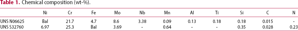
Chemical composition (wt-%).
A machine fitted with servomotors, and automated control systems carried out FSW process using a threaded tool from MegaStir™, which is based on polycrystalline cubic Boron Nitride (pcBN), with W-Re (binder phase). The tool shoulder diameter was 25.0 mm with probe of 3 mm length. The welding direction is according the rolling process of the sheets. To minimise oxidation during FSW, an argon atmosphere (at a flow rate of 50 L min−1) was employed. A schematic sketch of the FSW process is presented in Figure 1.
Schematic sketch of friction stir welding, including the dimensions (in mm).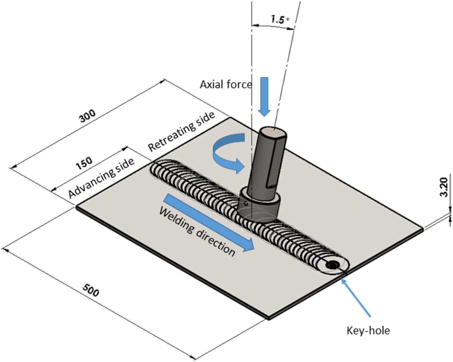
 was estimated by the ratio of delivered power
 and welding velocity
 as follows:

 is determined from the angular velocity
 per period and applied torque
 via
via
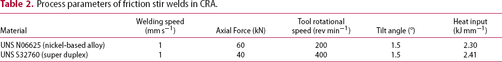
 . The process parameters used in this study are summarised in Table 2. In FSW parameter development for different CRA, similar heat inputs were achieved. This allowed comparing the response of FSW in CRA. It should be noted that the UNS N06625 is a Ni-based alloy, while the UNS S32760 is a super duplex stainless steel and, as a consequence, differences between these alloys can potentially impact in the corrosion resistance.
Process parameters of friction stir welds in CRA.
For the microstructural characterisation via optical microscopy (OM), the UNS N06625 joint was etched by Glyceregia (10 ml HCl, 10 ml HNO3, 0.5 ml of glycerine). On the other hand, the UNS S32760 joint was electrolytic etched by NaOH (40%).
To reveal the local mechanical properties, Vickers microhardness was the choice due to incomplete penetration evidenced by the macrographs (Figures 4 and 5). Therefore, lack of penetration has been a constant concern in FSW of high melting point alloys [18-21], which can be critical when welding alloys with high strain-hardening coefficients [21, 22]. Thus, the microhardness profiles were measured on the top surface with indentations of 300 g during 10s.
The pit corrosion resistance evaluation of the processed joints was done by means of the ASTM G48 method A. This procedure comprises pitting detection after keeping specimens immersed in a ferric chloride (FeCl3) solution. Prior the corrosion test, the samples’ surfaces were prepared by 80–1200 mesh sandpapers. Aiming to increase the test efficiency for these CRAs, the specimens were immersed in FeCl3 solution during 72 h at 60°C, which temperature is 10°C more than suggested by ASTM G48A. This higher temperature was chosen for enhancing pitting formation. The temperature was recorded by Pt100 thermocouple. After corrosion, the UNS S32760 joint microstructure (mostly affected by corrosion) was investigated via scanning electron microscopy (SEM).
Results and discussion
The resulting friction stir welds for both CRA are illustrated in Figure 2. From the surface appearance, it can be seen that the friction-stir-welded UNS N06625 nickel-based alloy, Figure 2(a), evidences a smoother appearance than that of the friction-stir-welded UNS S32760 super duplex, Figure 2(b). This indicates better welding condition in the case of UNS N06625 joint.
Top surface appearance of friction stir welds in: (a) UNS N06625 and (b) UNS S32760.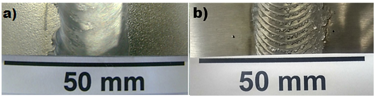
In Figure 3, the thermal cycles of friction stir welds in CRA are presented (temperatures measured at 15 mm distance from the weld centreline). Therefore, it is likely that the temperature towards the centre of the stir zone would be higher. As expected, the peak temperature on the advancing side (AS) was higher to that of the retreating side (RS) due to FSW characteristic, which asymmetry was also verified herein. In case of UNS S32760 joint, a temperature up to 509°C was reached, while in UNS N06625 joint the highest temperature was found to be of 513°C. Moreover, in UNS N06625 joint, the difference between the peak temperature of AS and RS was lower (approx. 77°C) and this might be related to the nickel-based alloy stability. On the other hand, the UNS S32760 joint had a variation among the highest RS and AS temperatures of around 115°C.
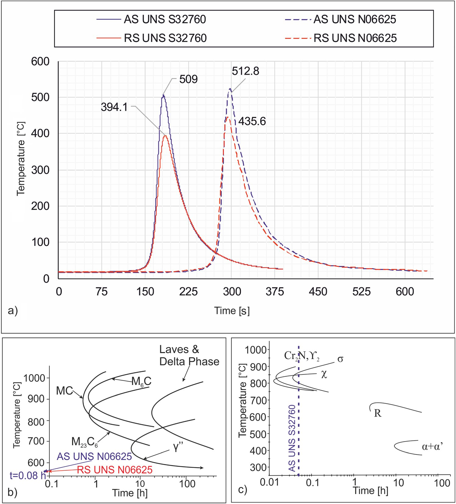
The thermal cycles of friction stir welds in CRA can be of help to identify the microstructure based on time-temperature-transformation (TTT) diagrams. Therefore, the TTT diagrams of these alloys (UNS N06625 and UNS S32760) are shown in Figure 3(b,c), respectively. These correlations are important for microstructural transformations in the heat affected zone (HAZ), where only thermal phenomena occur [25]. In this context, the microstructural changes that might affect UNS N06625 would take place inside the ‘C’ curves of the phases, as displayed in Figure 3(b) and reported in Refs. [23, 26]. However, such alterations did not happen in the current work (outside of the TTT diagram, as indicated by the red and blue arrows in Figure 3(b)) because neither the maximum temperature was high enough, nor the time at the temperatures was sufficiently long to induce the reactions (time and peak temperature were 6 min and 513°C respectively, as evidenced in Figure 3(a)). On the other hand, in UNS S32760, the harmful microstructural transformations can occur rapidly (Figure 3(c)) in conditions as χ = 0.15 h at 850°C, and σ = 0.4 h at 870°C [24]. Thus, in friction-stir-welded UNS S32760, although Cr2N, secondary austenite, and sigma (σ) phase could have been present (see doted blue line in Figure 3(c)), it is suggested that χ phase was formed (on the AS).
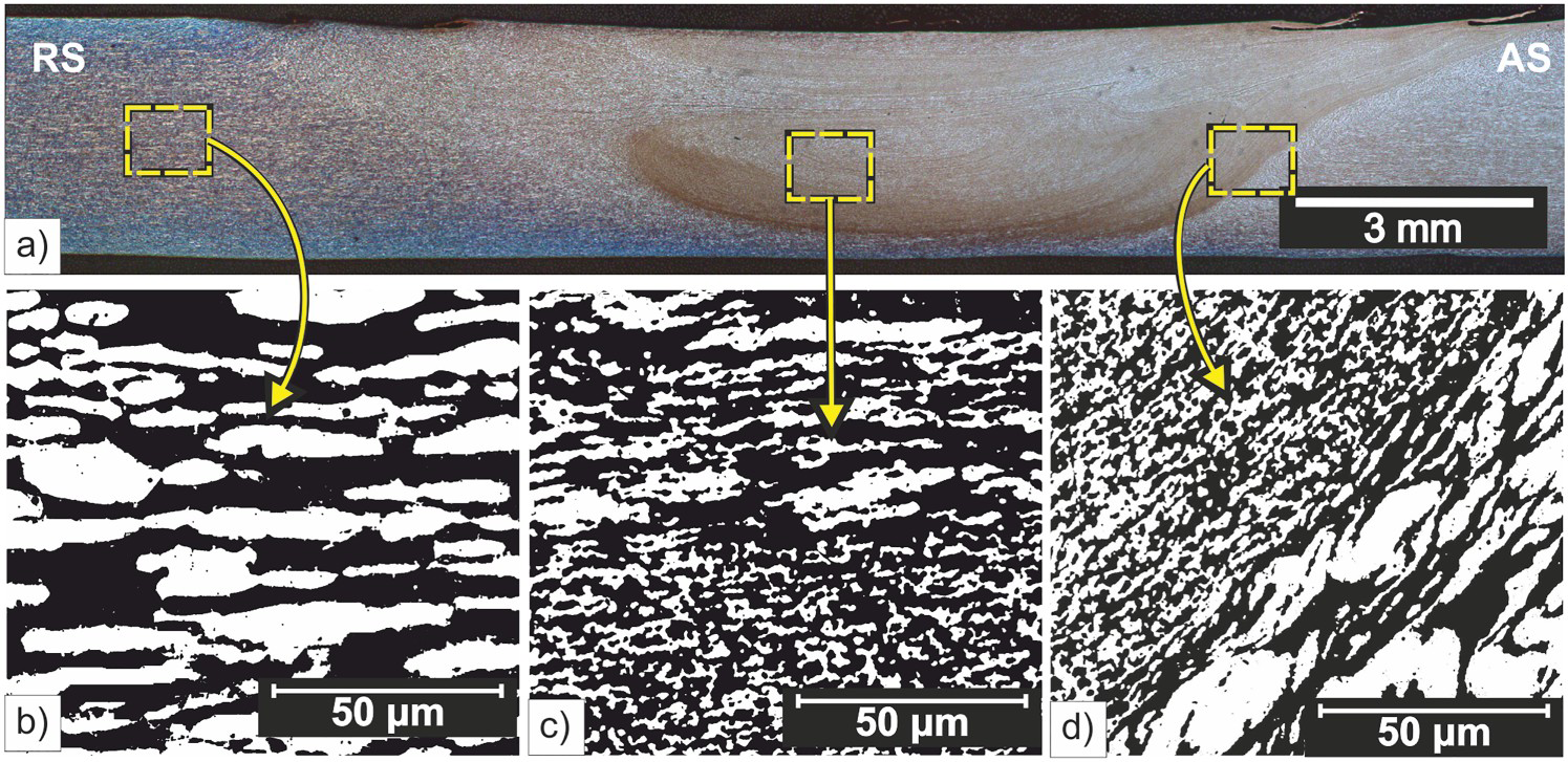
In Figures 4 and 5, the macrostructures of both friction-stir-welded alloys are shown. The friction-stir-welded CRAs exhibited a stir zone microstructure composed by small-sized grains. Besides, a darker region was identified in the macrostructures, which may be related to the pcBN tool wear, as reported similarly in Refs. [25, 27].
UNS N06625: (a) weld macrostructure, (b) base material, (c) stir zone. UNS S32760: (a) weld macrostructure, (b) base material, (c) stir zone, (d) interface.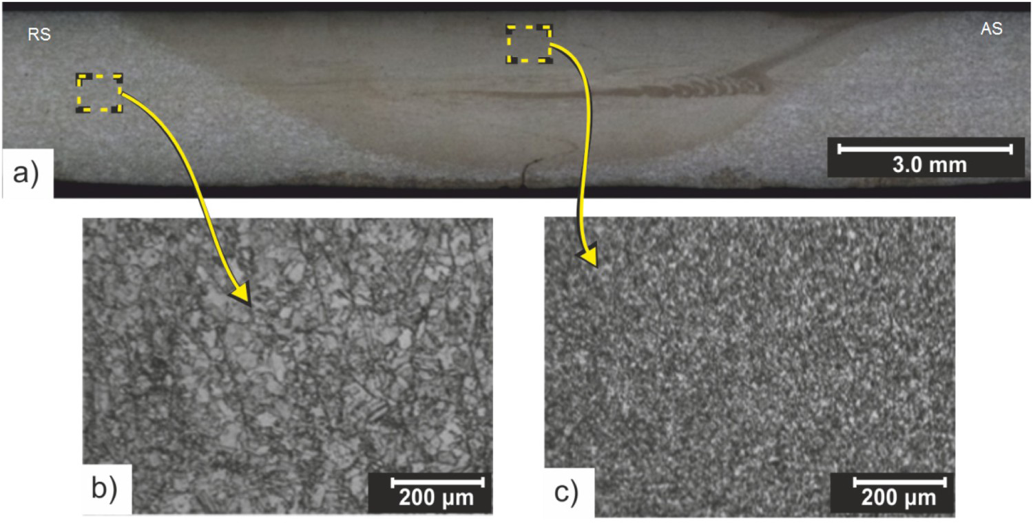
UNS N06625 (Inconel 625) base material microstructure (Figure 4(b)) consists primarily of austenitic grains which are still present after FSW but at a smaller size (Figure 4(c)), as noted in Refs. [25, 27, 28]. Therefore, this nickel-based alloy shows an austenitic microstructure either before or after FSW. Prior work presented that the alloy 625 grade I (base material in the soft annealed condition) has M(C, N) carbonitrides as well as carbides (M6C and M23C6), as shown in Ref. [28]. However, carbides were dispersed and present only at isolated grain boundaries, so that they do not represent the main microstructure. Still, it is not surprisingly that the friction-stir-welded UNS N06625 still has an austenite microstructure, which resulting phase may have superior pitting resistance, as suggested in Ref. [11]. Finally, it is believed that FSW can mitigate the susceptibility to sensitisation of UNS 06625 by the microstructure refinement, and possibly vanishing the carbides from the grain boundaries. Similar features have been observed in stainless steel [29] and AA 5083 aluminium alloy [30].
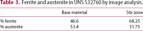
Ferrite and austenite in UNS S32760 by image analysis.
As above mentioned, grain refinement in CRA occurred trough FSW. The formation of small-sized grains induced by FSW can be explainable through the dynamic recrystallisation caused by the synergic interaction between plastic flow and heat generated. These two variables are enough intense to drive the recrystallisation process [21]. Thus, FSW was effective for achieving a refined microstructure in CRA.
Figure 6 shows that the UNS N06625 joint possesses improved values that are related to small-sized autenite phase within the stir zone, which is the major microstructure. On the other hand, the friction-stir-welded UNS S32760 SDSS presents a significant microhardness variation on the AS, which can be associated to the higher heat input and intermetallic precipitation. Moreover, the contribution of each alloying constituent (matrix and precipitates) could not be isolated in the microhardness test, since the indentation tool is of several orders larger than the precipitates. Therefore, the microhardness values in this region represent the combination of both matrix and precipitates and thus increased values were verified. Finally, as an average, the UNS S32760 stir zone reveals slightly higher microhardness due to small-sized phases (austenite and ferrite).
Microhardness profiles measured on the top surface of friction-stir-welds in CRA.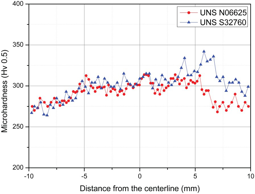

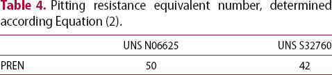
Pitting resistance equivalent number, determined according Equation (2).
No pitting formation was seen in the stir zone of friction-stir-welded UNS N06625 even tested with 10°C more than indicated by ASTM G48A. However, Figure 7 shows a pit found in the base material, where the blue colour is the surface and the red is the depth. OM revealed that the maximum pit depth is below 0.025 mm, as shown in Figure 7(b). Therefore, it was a shallow pit (1.2 µm) not significant according ASTM G48. Moreover, it is interesting to note that this nickel-based alloy, even having varied carbides on its microstructure (reported in Ref. [28]), it has not presented substantial localised corrosion, thus proving its outstanding pitting corrosion properties and stability [23]. Hence, the corrosion tests showed that the friction-stir-welded UNS N06625 does not have substantial pitting corrosion under the corrosion condition analysed.
Pitting in the base material (UNS N06625): (a) topographic image, (b) pit depth profile.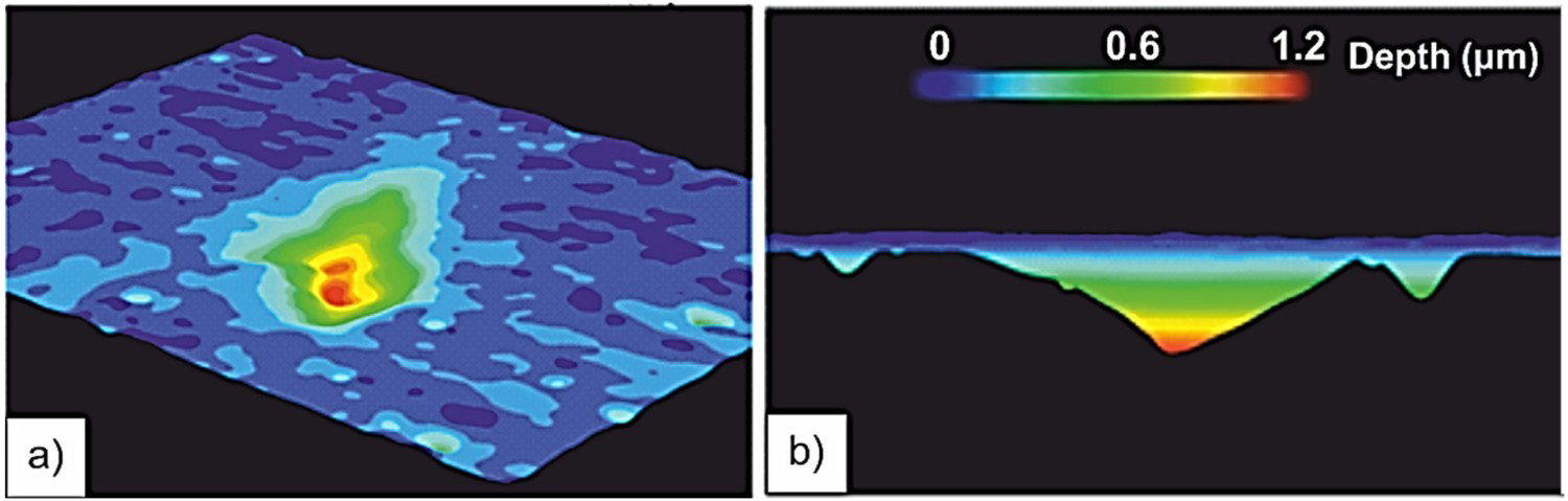
In friction-stir-welded UNS S32760 super duplex, the intermetallic compounds were clearly observed on the AS (detailed in Figure 8(b)). It is evident that the precipitation due to FSW occurred at grain boundaries of the ferrite phase. This phenomenon can be further seen in Figures 9 and 10. It is thus supposed that χ phase was formed on the AS and this phenomena led to depleted Cr and Mo in the adjacent ferrite, promoting Cr and Mo depleted regions nearby the precipitates, thus creating sites for pit initiation, as in Refs. [34-36]. On the other hand, no significant corrosion was noted in the stir zone.
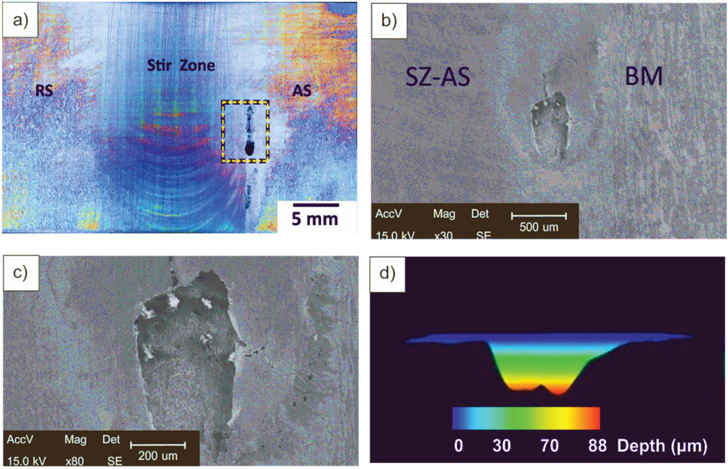
Top surface of friction-stir-welded UNS S32760: (a) before ASTM G48A test, (b) intermetallic precipitation in detail on the AS. Friction-stir-welded UNS S32760 right after ASTM G48A: Pitting on the advancing side (AS): (a) macrograph evidencing flaws in the rectangle, which are zoomed in (b), and blister and cracks indicated by #1 in (c). Friction-stir-welded UNS S32760 one week after ASTM G48A test: (a) Localised corrosion on the advancing side (AS). In (b) and (c), SEM images show the pit width. In (d) pit depth is shown.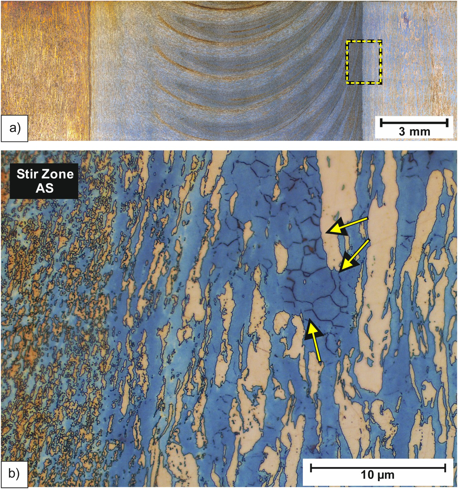
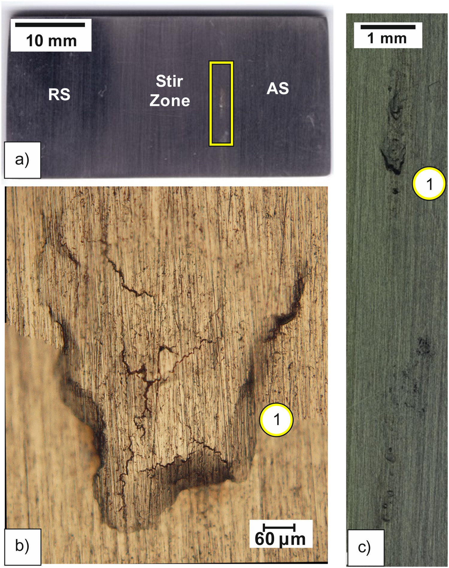
The heat input in friction-stir-welded UNS S32760 was noted to be higher, promoting intermetallic precipitation and further pitting corrosion. Thus, the UNS S32760 joint showed clear pitting on the AS (Figure 9). The pitting located on the AS is associated with the higher process temperatures than the RS [25] as well as intermetallic precipitation on the ferrite phase, consistent with [37]. Therefore, the corrosion morphology observed in Figure 9 suggests that depleted regions close to precipitates behave as a preferential site for pitting formation. Hence, the solution entered into the sample causing blistering and, subsequently, cracking. In practice, as the top surface is normally exposed to the environment, the deterioration of pitting resistance in UNS S32760 joint is undesirable.
One week later, the local corrosion process that occurred on the AS of friction-stir-welded UNS S32760 (Figure 9) became to a large pit, as shown in Figure 10(a) and evidenced by SEM images in Figures 10(b,c). Then, using OM, it was estimated that the pit profile and depth were 0.3 mm and 88 µm, respectively; this evolution is due to the autocatalytic characteristic (Figure 10), as stated in Ref. [11]. Therefore, this narrow pit was found to be of around seven times deeper than the one observed in the base material of friction-stir-welded UNS N06625 (Figure 7). Thus, the corrosion test mostly affected the friction-stir-welded UNS S32760 super duplex.
Conclusions
An investigation was carried out to verify the response of friction stir welding (FSW) in distinct corrosion resistant alloys (CRA) used in related applications of the oil and gas industry. Therefore, similar heat inputs were achieved by FSW in two CRA (a nickel-based alloy (UNS N06625) and a super duplex stainless steel (UNS S32760)). The findings of the current work can be overviewed as follows:
The UNS N06625 joint was not susceptible to pit corrosion under the corrosion test employed, which is in agreement with its higher PREN and corrosion properties. On the contrary, the UNS S32760 joint experienced corrosion, consistent with the higher heat input and intermetallic precipitation (on the ferrite phase) promoted by FSW. The results also showed that FSW has not deteriorated the high corrosion resistance and stability of UNS N06625, indicating that solid state welding is promising for nickel-based alloys.
Footnotes
Acknowledgements
The authors would like to acknowledge the financial support of CAPES PROBRAL-88881.198810/2018-01.
Disclosure statement
No potential conflict of interest was reported by the author(s).