
Abstract
The micro-resistance spot welding is widely used for low-to-medium-volume applications due to its low cost, especially for cylindrical Lithium-ion cell-based modules. Using typical micro-resistance spot welding electrodes in a series configuration, two nuggets/welds are created in a single welding operation. As it is a contact joining process, productivity is limited. This paper developed a novel approach to enhance the productivity of micro-resistance spot welding, where four nuggets were produced instead of two nuggets in a single operation. The critical-to-quality criteria, including joint strength, microstructure, electrical resistance and temperature rise at joints, were demonstrated by comparing the existing and proposed approaches. A reduction in cycle time by up to 57% can be achieved by adopting the proposed approach while maintaining the weld quality.
Keywords
Introduction
The micro-welding is widely used for meeting advanced joining requirements such as microelectronic packaging, manufacturing medical components or electric-mobility battery developments. A wide range of micro-joining techniques has been investigated to meet these requirements, especially for electric vehicle battery pack development, including laser welding [1], ultrasonic welding [2], micro-resistance spot welding [3,4], micro-TIG welding [5], ultrasonic wedge bonding [6], mechanical fastening [7], etc. Micro-resistance spot welding (micro-RSW) is particularly attractive to micro-mobility manufacturers due to its low maintenance and investment costs, easy quality control and ease of operation; furthermore meets the market demands low-to-medium-volume applications, such as e-bikes, two-wheelers or e-rickshaws [8]. However, micro-RSW is a contact joining where the electrodes touch the work surfaces and then produce the weld. Therefore, it is inherently slower than non-contact joining such as laser welding [9]. Therefore, there is a need for micro-RSW productivity improvement such that its benefits can be released to meet industrial demands.
Industrial demands
Due to recent advancements in battery electric vehicles including micro-mobility e-vehicles (smaller and lighter), they are being increasingly used to reduce or eliminate the emission of greenhouse gases [10–12]. Often these electric vehicles (EVs) use cylindrical cell-based battery packs. This battery pack is composed of several battery modules and those modules are built using individual cells which need tab-to-cell terminal joining. Figure 1 shows the configuration of cylindrical cells to build the module from individual cells and several modules to build the pack [3]. Therefore, efficient micro-welding methods are needed to meet the growing manufacturing demand for battery electric vehicles.
Hierarchical steps to build battery packs from cylindrical cells [3].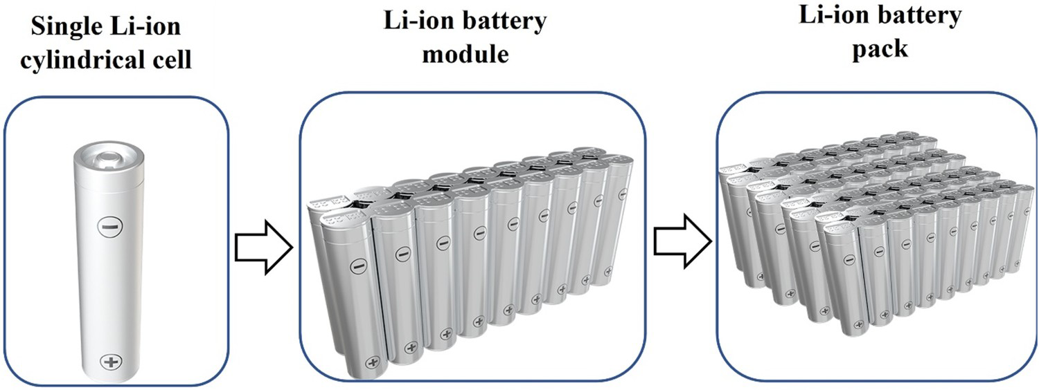
Related research on micro-RSW
Various aspects of the micro-RSW joining, such as appropriate materials for tab-to-terminal connections [4,8,13], the electrode sticking mechanism/factors [14], the process parameters study [4,8,9], nugget diameter study [15], weld quality study [16,17], are reported in the literature. In general, the series type is the preferred electrode configuration for welding the tab to Li-ion cylindrical cell terminals as two separate welds are created in a single welding operation [18]. However, only two weld nuggets are not sufficient (i) to meet the critical-to-quality requirements, such as joint strength and electrical resistance (i.e. may lead to excessive heating during the charge–discharge cycle) [3], and (ii) to restrict the cell rotation within the battery module due to vehicle vibrations [3]. Therefore, four weld nuggets are placed instead of two weld nuggets to satisfy the earlier requirements, and they are produced in two subsequent steps. Firstly, two welds are produced and then moved to the following location for placing another two welds (also termed as 2 + 2 nuggets formation). In addition, our recent study [3] explored the in-depth analysis of micro-RSW joining, including optimisation of process parameters, microstructural analysis of nuggets, electrical resistance and temperature responses during the application of charge/discharge when a series of electrode configurations were used for 2 + 2 nuggets formation. Readers interested in exploring various aspects of 2 + 2 nuggets formation are directed to the published paper [3]. The 2 + 2 nuggets formation approach has limited productivity due to the higher cycle time. Therefore, there is a need for an alternative approach to meet the productivity requirements.
Objectives
To reduce this higher cycle time, a novel approach has been developed in this paper where four welds can be produced simultaneously (termed as the 4 nuggets formation). Thereafter, the critical-to-quality criteria obtained from the 4 nuggets formation were compared with the 2 + 2 nuggets formation to demonstrate the viability of the proposed technique. Joint strength, microstructural characteristics, electrical resistance and temperature rise at the joint were evaluated for successful implementation of the 4 nuggets formation technique.
Experimental details
Materials and methods
Sample preparation and machine details: Nickel-plated steel [19] with a dimension of 35 mm × 10 mm × 0.3/0.4 mm and nickel (Ni) with a dimension of 35 mm × 10 mm × 0.2 mm were used. The composition of the nickel-plated steel was 0.047% C, 0.235% Mn, 0.011% P, 0.010% S, 0.059% Al, 0.002% Si, 0.0019% B and balanced Fe [3]. Whereas, the Ni tab was Ni > 99%, Mn < 0.35%, Cu < 0.25%, Si < 0.35%, C < 0.15%, S < 0.01% and Fe < 0.40% [3]. For Ni to nickel-plated steel lap welding, a resistance spot system (Make: MacGregor; Model: M31 Smart Series) having 3- mm-diameter pure copper electrodes with a domed-shape and a maximum working output current flow of 6000 A DC was used. For the electrode tip geometry, the domed electrode tip was better than the other electrode tip geometries (e.g. flat, tapered, etc.) in terms of the electrode's life span and oxidation [8]. The inter-electrode distance between the negative and positive electrodes was kept constant (6.5 mm) throughout the experiments.
Welding process, microstructural and joint strength evaluation methods: Welded samples were tested for strength, metallurgical analysis, and electrical and thermal performances to determine the optimised welding parameters (e.g. weld current, weld time, squeeze time, pre-heat current, pre-heat time, dwell time and hold time). Subsequently, the optimised process parameters were utilised to weld the Ni tab to 18,650 Li-ion/cylindrical cells. For microstructural evaluation, joints were ground and mechanically polished for the analysis under an optical microscope (Make: Nikon; Model: LV150N). Lap shear tests were conducted on an Instron 3367 test frame with a crosshead speed of 2 mm/min.
Electrical resistance and temperature measurement methods: The resistance of the welded coupon specimens and the four-point probe measurement technique was applied [3]. Due to the effect of Joule heating [1], high joint resistance results in more power loss (
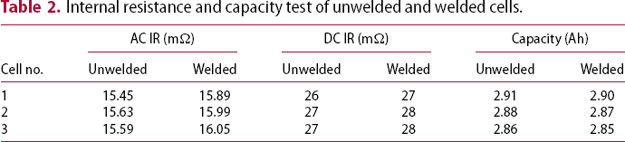
Performance evaluation methods of welded live cells: The 18,650 Li-ion cylindrical cells (3.0 Ah) were used for micro-RSW trials. To evaluate the electrochemical performance of cells as a result of micro-RSW joints, a reference performance test (RPT) was performed for unwelded and tab-welded cells. Three cells were used for this analysis to estimate the cell-to-cell variation. During the RPT, cell discharge capacity and DC internal resistance (IR) were measured to identify any detrimental effect on cell performance. This characterisation procedure comprised a constant current–constant voltage (CC-CV) measure of energy capacity at a current magnitude of 0.3C. During each test the transition to constant voltage occurred at 4.2 V, with the charge continuing until the value of current reduced below C/30. The capability (Ah) of the cells was evaluated through a sequence of pulse discharges by a power capacity test, in which a current magnitude of 3C was applied for a duration of 10 s at SOC levels of 50%. All experiments were conducted within a climate chamber set to 25°C. AC IR was also measured using the HIOKI battery Hitester (Model: 3563) to examine the joint quality in terms of change in resistance of welded and unwelded cells. So, these electrical tests were performed to understand the adverse effect of welding on cells [21].
Electrode design modification
Figure 2(a,b) show the schematic of electrode configurations and actual weld head images used for the 2 + 2 and 4 nuggets formation, respectively. The stepwise 2 + 2 and 4 nuggets formation with representative cycle time required to complete terminal welding of a cylindrical cell is shown in Figure 2(a,b), respectively. To place four nuggets at one terminal, it is apparent from Figure 2, that the number of steps, subsequently cycle time, can be reduced by half when the 2 + 2 nuggets formation (i.e. 8 step process) method was replaced with the 4 nuggets formation (i.e. 4 step process) method.
Schematic of electrode configurations and actual weld head images with representative steps and the time required for (a) 2 + 2 nuggets (b) 4 nuggets formation [assuming electrode moving time 0.5 s; weld time 0.2 s].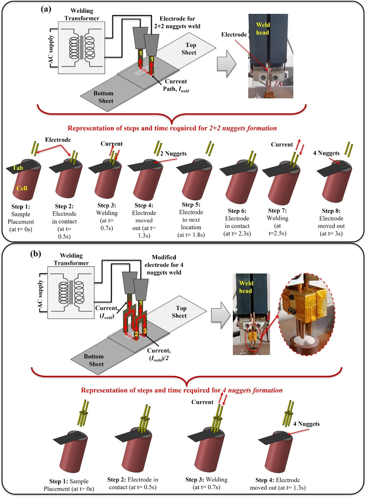
For the 4 nuggets formation, the electrode shown in Figure 2(a), is modified into an electrode with two legs with the help of a fixture (made of the copper block) and two other electrodes of the same dimensions. Because of this, the current supplied on electrode 1 (Figure 2b) will be divided equally into electrodes 2 and 3 (Figure 2b) and generate heat at the faying surface, resulting in multiple joints. The tip of electrodes 2 and 3 should be appropriately adjusted at the same height as the top surface of the welding parts, otherwise, the contact area and pressure between the electrode and the samples will differ. Subsequently, non-identical nuggets will be obtained after welding. Therefore, the adjustment of the electrodes is critical to creating identical nuggets.
Results and discussions
For electric vehicle battery joining, critical-to-quality criteria must be satisfied. Only analysis of joint strength behaviour is not sufficient. Electrical resistance and temperature rise at the joint locations are equally important. Therefore, this section reports the joint strength analysis in ‘Joint strength and weld nugget analysis’ section, electrical contact resistance and temperature rise during the application of representative electric current in ‘Analysis of electrical contact resistance and temperature’ section. Furthermore, the results of using the proposed 4 nuggets formation method were validated by demonstrating cylindrical cell joining in ‘Verification and validation using 18,650 cylindrical cells’ section. Thereafter, a critical review of the proposed method is reported in ‘Critical analysis of the proposed 4 nuggets formation technique’ section
Joint strength and weld nugget analysis
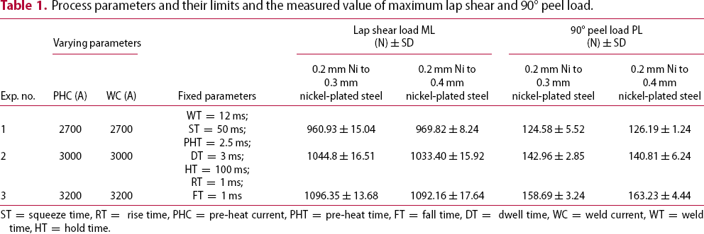
In the previous study by Kumar et al. [3], lap shear and T-peel tests of micro-RSW joint samples were carried out using the 2 + 2 nuggets formation process. Subsequently, preferred welding parameters were determined according to the load-displacement features and failure modes obtained from lap shear and T-peel tests. The same approach was adopted in this study to optimise the welding parameters for the 4 nuggets formation process. Table 1 shows the selected parameters with levels and their corresponding average values of maximum lap shear load (ML) and 90° peel load (PL) for the 4 nuggets formation weld using both 0.2 mm Ni to 0.3/0.4 mm nickel-plated steel joints. Each experiment was performed three times, and associated standard deviations were obtained. The range of process parameters was selected based on trial experiments conducted using a one-factor-at-a time approach (i.e. obtained by varying one parameter at a time while keeping the other parameters at a constant value). In Table 1, PHC and WC were considered as varying process parameters, and other parameters (WT, ST, PHT, DT, RT, FT and HT) were kept constant. The minimum and maximum values of ML and PL were obtained from experimental no. 1 (WC = 2700 A and PHC = 2700 A) and 3 (WC = 3200 A and PHC = 3200 A), respectively for both 0.2 mm Ni to 0.3/0.4 mm nickel-plated steel joints. The output response, ML and PL were increased with increasing PHC and WC, and the ML and PL were maximum at a higher value of PHC and WC. This is because the weld nugget size was increased and subsequently, produced a deeper penetration depth and a wider interface width which resulted in higher joint strength [3]. The images of the 0.2 mm Ni to 0.3 and 0.4 mm nickel-plated steel micro-RSW-welded samples from experiments no. 3 are shown in Figure 3(a,c), respectively, and their corresponding weld nuggets are shown in Figure 3(b,d). It could be observed that the nuggets of both Figure 3(b,d) do not have any blowholes and cracks, which attributes to their higher joint strength. Therefore, from Table 1, the preferred value of WC and PHC required for the good/high strength weld was 3200 A for both 0.2 mm Ni to 0.3 and 0.4 mm nickel-plated steel combinations.
Micro-RSW sample and an area of molten and subsequently solidified metal at WC = 3200 A; PHC = 3200 A for 0.2 mm Ni to (a, b) 0.3 mm nickel-plated steel and (c, d) 0.4 mm nickel-plated steel. Process parameters and their limits and the measured value of maximum lap shear and 90° peel load. ST = squeeze time, RT = rise time, PHC = pre-heat current, PHT = pre-heat time, FT = fall time, DT = dwell time, WC = weld current, WT = weld time, HT = hold time.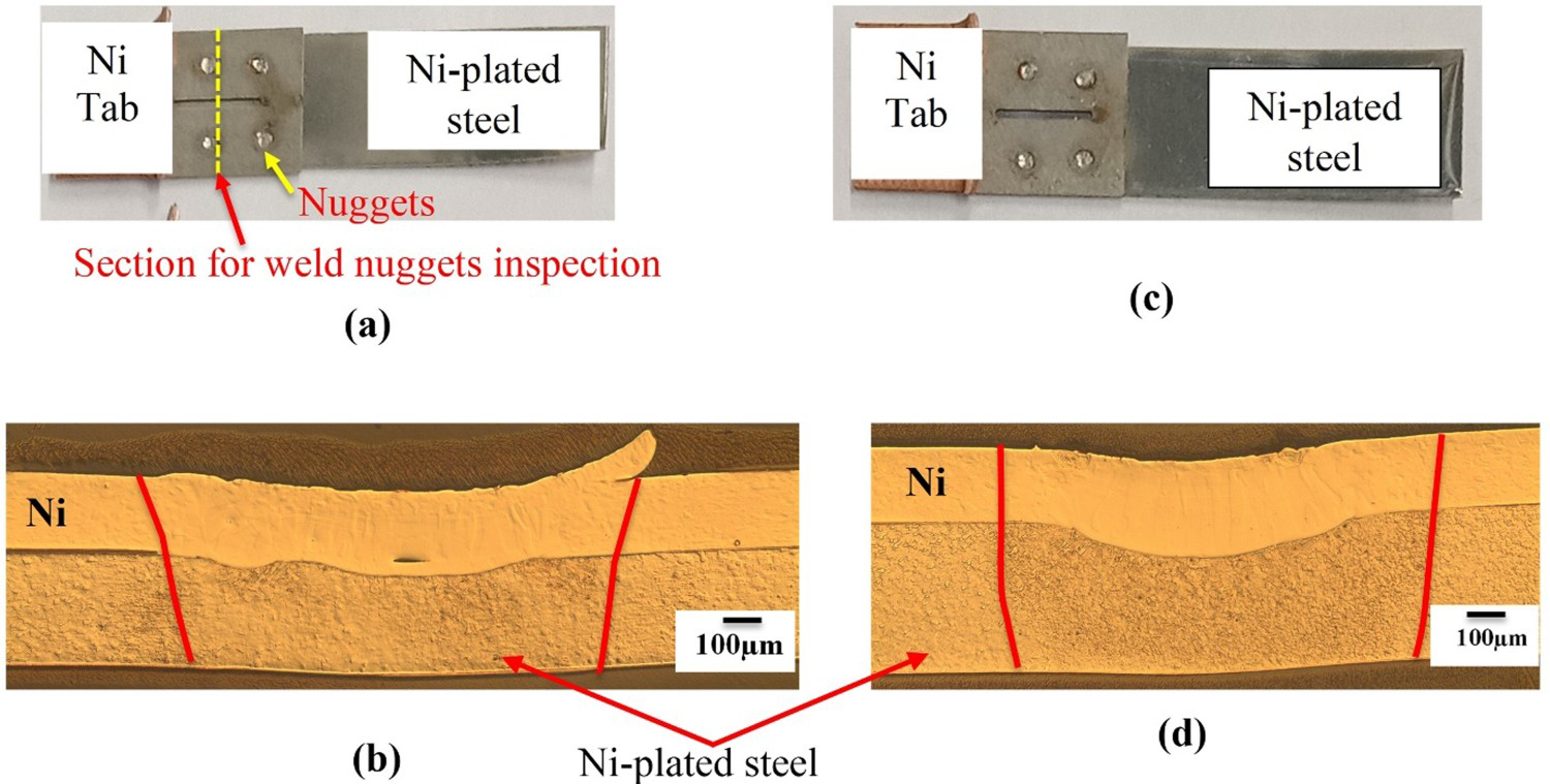
From the results, the maximum lap shear load obtained from the 4 nuggets formation weld (1096.35 N) was about 2.5% more than the 2 + 2 nuggets formation weld (1071.90 N) for the 0.2 mm Ni to 0.3 mm nickel-plated steel weld. Whereas the maximum load obtained from the 0.2 mm Ni to 0.4 mm nickel-plated steel with the 4 nuggets formation weld (1092.16 N) is about 3.5% lower than the 2 + 2 nuggets formation weld (1136.79 N). For the 4 nuggets formation, the shear load from 0.2 mm Ni on 0.4 mm nickel-plated steel (1092.16 N) was less than the shear load obtained from 0.2 mm Ni on the 0.3 mm nickel-plated steel (1096.35 N) because the weld interface width (Figure 3d) was smaller (1.07 mm) than the 0.2 mm Ni to 0.3 mm (Figure 3b) nickel-plated steel joint (1.14 mm), which attributed to a lower shear load [3,4]. So, there was only a small difference (about 3.5%) in the maximum load value obtained between the 0.2 mm Ni to 0.3/0.4 mm nickel-plated steel for 2 + 2 and the 4 nuggets formation weld, which validated the proposed electrode design to weld 4 nuggets at a time with about 57% less cycle time compared to the 2 + 2 nuggets formation. Also, from the cross-sectional images (Figure 3), no bottom surface penetration and very small bending were obtained which is ideal for battery application because full penetration can produce cracks leading to electrolyte leakage or potential thermal runaway [17]. In addition, the recommended weld current value for both 0.2 mm Ni to 0.3/0.4 mm nickel-plated steel combination for the 4 nuggets (3200 A) formation welds is more (about 60%) than the 2 + 2 nuggets formation weld (i.e. 2000A for 0.2 mm Ni to 0.3 mm nickel-plated steel and 2100 A for 0.2 mm Ni to 0.4 mm nickel-plated steel). Also, the pre-heat current (3200 A) required for the 4 nuggets formation weld is equal to the weld current (3200 A) required for the 4 nuggets formation weld and about 170% more than the 2 + 2 nuggets formation weld (1200 A) for both 0.2 mm Ni to 0.3/0.4 mm nickel-plated steel. Whilst all other parameters values (WT = 12 ms; ST = 50 ms; PHT = 2.5 ms; DT = 3 ms; HT = 100 ms; RT = 1 ms; FT = 1 ms) were the same for both 4 nuggets and 2 + 2 nuggets formation welds to achieve good quality weld. Since 4 nuggets were generated simultaneously in the 4 nuggets formation weld using the set-up described in ‘Experimental details’ section (Figure 2b), welding required large weld and pre-heating currents. Also, the effect of the large weld and the pre-heat currents on the cell performance before and after welding were examined in ‘Verification and validation using 18,650 cylindrical cells’ section.
Similarly, it was important to evaluate the 90° peel load (PL) as these parameters would be used for live cell joining. From Table 1, at the preferred value of process parameters (i.e. exp. no. 3) the maximum 90° peel load (PL) values were obtained as 158.69 N and 163.23 N for 0.2 mm Ni to 0.3/0.4 mm nickel-plated steel joints, respectively. From 90° peel test results from both 0.2 mm Ni to 0.3/0.4 mm nickel-plated steel joints showed that there was a slight difference (about 2.5%) between 2 + 2 and 4 nuggets formation welds, which also strengthened the potential of the newly introduced electrode design for producing good quality 4 nuggets weld at a time.
Analysis of electrical contact resistance and temperature
Joint resistance and temperature rise at joints are important responses that should be analysed to produce an efficient battery module. Joint resistance and temperature were captured when a current of 20 A passed through the joints for 180 s [1,3] to eliminate the drift effects during the measurement cycle. In Figure 4(a,b), comparisons were made between the resistance and temperature with time for the 2 + 2 and 4 nuggets formation when 0.2 mm Ni to 0.3 mm nickel-plated steel stack-up was used. When the current was passed through the welded specimens, resistive heat loss generated heat increased the resistance of the joint and worked as a positive feedback loop [1]. At the end of 180 s of the current application, the resistance increased to 0.901 mΩ for the 2 + 2 nuggets formation sample and 0.898 mΩ for the 4 nuggets formation sample, which was about 8.81% and 8.45% increase in resistance from an initial resistance value of approximately 0.828 mΩ, respectively. In addition, the difference in resistance between the 2 + 2 nugget and the 4 nuggets formation weld at the end of 180 s is 0.003 mΩ. Similarly, the temperature rise was captured from a room temperature of 24°C. The maximum temperatures at the end of 180 s were around 38.2°C and 37.6°C for 2 + 2 and 4 nuggets formation welds, respectively. Figure 4(c) shows the thermal image of the joint area, captured during the test at t = 60, 120 and 180 s. It can also be concluded from Figure 4(a,b) that the curves obtained from 2 + 2 and 4 nuggets formation joints were almost congruent, i.e. the insignificant effect on resistance and temperature rise. Therefore, the proposed 4 nuggets formation method can produce a similar weld as in the 2 + 2 nuggets formation.
Profiles of (a) joint resistance (b) temperature measurement of 0.2 mm Ni to 0.3 mm nickel-plated steel joint at 20 A supply current for both 2 + 2 and 4 nuggets formation weld and (c) IR thermal images of weld area as a result of current flow at t = 60, 120 and 180 s.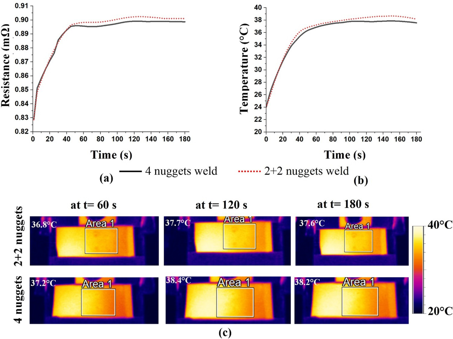
Verification and validation using 18,650 cylindrical cells
A pictorial view of the negative terminal of the welded cell is shown in Figure 5(a). The 90° peel load obtained from the Ni tab to the negative and positive terminal was 152.68 N and 167.41 N, respectively. In addition, there was only a small difference (about 2%) in the 90° peel load value obtained when the 2 + 2 nuggets formation was replaced with the proposed 4 nuggets formation weld. It is evident from the 90° peel load results that satisfactory high-strength joints can be achieved for the tab-to-cell terminals by implementing the 4 nuggets formation weld techniques. An autopsy of the welded cell was conducted to check the internal tab joint after welding, especially for the negative terminal.
(a) Pictorial view of live cell welding of the negative terminal at WC = 3200 A; PHC = 3200 A (b) autopsy of the negative terminal and cross-sectional image of internal tab joint (c-f) cross-sectional view of the nugget 1–4 of Figure 5(a), respectively; temperature rise profile during the welding of (g) negative (h) positive terminals.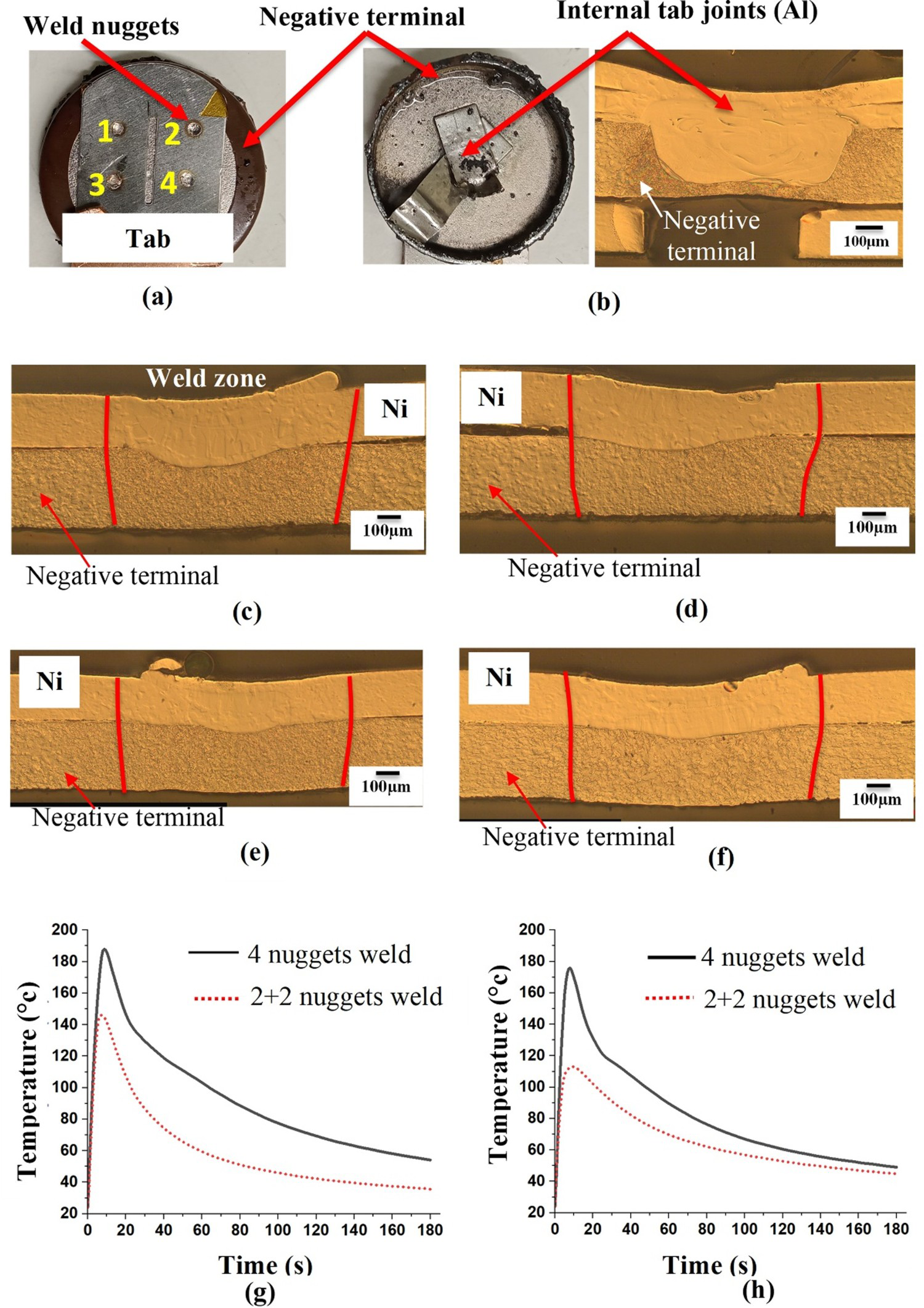
The internal tab joint of the negative terminal after welding the external 0.2 mm Ni tab at optimised process parameters is shown in Figure 5(b), which shows no issues/fractures occurred due to the external tab to the negative terminal welding. This issue was not there for the positive terminal as it is free from any internal tab connection. In Figure 5(a), the nuggets were numbered from 1 to 4, and their cross-sectional images are shown in Figure 5(c–f), respectively. From Figure 5(c–f), it can be concluded that no bottom surface (cell terminal) penetration and almost no bending were obtained, which was ideal for battery application. Figure 5(g,h) show, the temperature rise profile during the welding of the tab to negative and positive terminal, respectively for both 2 + 2 and 4 nuggets formation. The maximum rise in temperature in the case of 2 + 2 nuggets formation was 146.2°C and 113.1°C for negative and positive terminal joints, respectively. Whereas, the maximum temperature measured for the 4 nuggets formation was 187.4°C for the negative and 175.8°C for the positive terminal. Furthermore, the maximum temperature captured for the 4 nuggets formation was higher than the 2 + 2 nuggets formation because the pre-heat and weld current applied for the 4 nuggets formation is higher than that of the 2 + 2 nuggets formation weld.
In addition, the weld quality was evaluated based on the electrical characterisation in terms of internal resistance and capacity test. Figure 6(a,b) show the schematic and actual set-up of the Maccor cycler connections for DC IR and capacity measurement. All cells were stored under open circuit conditions at 25°C in an environmental test chamber, as shown in Figure 6(a). Figure 6(c) shows the schematic of voltage response to current load and internal resistance calculation (i.e. measuring the voltage drop ( DC internal resistance and capacity testing set-up (a) schematic diagram (b) actual and (c) schematic of RPT/pulse power test and internal resistance measurement. Internal resistance and capacity test of unwelded and welded cells.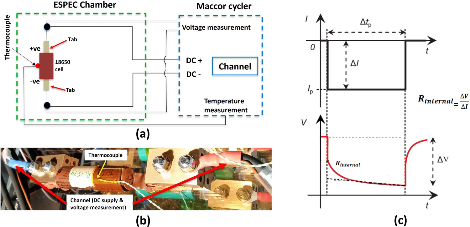
Critical analysis of the proposed 4 nuggets formation technique
From the foregoing analysis, the proposed electrode can produce high-quality 4 nuggets simultaneously by satisfying critical-to-quality requirements. The joint strength, electrical resistance and temperature rise at the joint obtained from the 4 nuggets formation weld were almost equal to the 2 + 2 nuggets formation. In contrast, the time required for welding one terminal of the cylindrical cell using the 4 nuggets formation technique is about 57% less than that of the 2 + 2 nuggets formation. However, the following precautions are to be taken for the successful implementation of the 4 nuggets formation technique:
All four electrode tips should be adequately adjusted at the same height from the workpiece; otherwise, non-identical nuggets will be obtained due to a misbalance of current flow from one electrode to another. Thus, the adjustment of the electrodes in this technique is critical to creating an efficient joint. The temperature rise during the welding for the 4 nuggets formation was greater than that of the 2 + 2 nuggets formation weld. However, no detrimental effect on weld quality was observed due to the high rise in temperature during the welding. Even the welded cell electrical test results were also satisfactory compared to the unwelded cell. The projection welding approach can be used to produce 4 nuggets simultaneously [22]. However, additional work is required for developing projected tabs before welding which may also have a detrimental effect on weld quality due to thinning of the sheet as a result of projection. The current technique eliminates the additional work such as projection (i.e. cost saving) and a good quality weld will also be achieved.
Conclusions
In this work, a novel electrode design was introduced to create 4 nuggets at a time to reduce the cycle time and increase the productivity of the micro-resistance spot welding technique. From the preceding analysis and discussion, the following conclusions were drawn:
The proposed electrode has the potential advantage of reducing the cycle time and increasing productivity during battery pack manufacturing. The cycle time reduction of around 57% can be obtained using the proposed 4 nuggets formation technique compared to the current 2 + 2 nuggets formation technique to perform terminal welding. The proposed method was validated by performing joint mechanical, metallurgical, electrical and thermal analyses. The variation of resistance and temperature rise with time across the joint for the 4 nuggets and 2 + 2 nuggets formation were almost congruent, validating the proposed technique. In the case of live cell welding, a small difference (about 2%) in the 90° peel load value was obtained when the 2 + 2 nuggets formation (i.e. 153.25 N and 172.91 N for negative and positive terminal joints, respectively) technique was replaced with the proposed 4 nuggets formation (i.e. 152.68 N for negative terminal and 167.41 N for positive terminal) technique. This demonstrated that the proposed 4 nuggets formation technique could successfully replace the 2 + 2 nuggets formation technique. The DC internal resistance was increased by only about 4%, and the capacity was decreased by about 0.3% when the welded cells were compared to the unwelded cell using the 4 nuggets formation weld, demonstrating the modified electrode's effectiveness.
Furthermore, welded cells can be used for in-depth electrical analysis (i.e. cycle life) in future work.
Footnotes
Disclosure statement
No potential conflict of interest was reported by the author(s).