
Abstract
Printed metallic parts often suffer from thermomechanical defects such as delamination, buckling and warping, and this effect is exacerbated in multi-arc additive manufacturing (AM) due to the extensive heat input and large molten pool. These defects originate primarily because of high residual stresses accumulated during layer-by-layer deposition. Here we develop, validate and employ a three-dimensional finite element model with two independent heat sources to analyse the thermomechanical responses in dual-arc parallel AM of Ti6Al4V thin-walled parts. The results are compared with those of the conventional single-arc AM. Although the deformation in dual-arc AM is slightly larger than that in single-arc AM, the stresses at the substrate-deposit interface for dual-arc AM are reduced by 53% due to the lower cooling rate.
Keywords
Introduction
As a crucial metal additive manufacturing (AM) technology, directed energy deposition – arc (DED-Arc) has the advantages of high deposition rate, low cost, and high manufacturing freedom, leading to the potential to fabricate large-scale, high-performance metallic components in many industry sectors [1,2]. However, components fabricated by DED-Arc are susceptible to high residual stresses and deformation due to the extensive heat input and large molten pool during the process, which may lead to delamination, warping and premature fatigue failure of the components [3–5].
Compared to experimental method, which is time-consuming and expensive, numerical simulation has been proven to be an effective way to obtain detailed information of the global thermomechanical conditions during the AM process accurately [6–9]. The existing research mainly focuses on a single heat source in AM [10–12]. Multi-energy source (MES) is a concept that applies more than one energy source to fabricate components at the same time. In recent years, MES has become a promising development trend of additive manufacturing technology [13,14]. MES has the advantages of high deposition efficiency and low cost, which provides a new way to realise large-size, high-performance, and batch-manufacturing process for metal parts. So far, most of the MES configurations have been used for laser-based additive manufacturing [15,16] or hybrid arc-laser applications [17,18], but literature on multi-arc AM is scarce. Only Geng et al. [19] studied the temperature and stress distribution of a single-layer structure in multi-arc AM by constructing a finite element (FE) model, and found that the maximum stress was located at the overlap region of the deposition bead where cracks frequently formed. In the related field of welding, there are some researches concerning the thermomechanical behavior of multi-arc heat sources. Li et al. [20] established a FE model to predict the residual stress in double-sided double-arc welding (DSDAW). It's found that the weldment had smaller angular deformation, lower residual tensile stress, and homogeneous stress distribution compared to that using single arc welding (SAW). Zhang et al. [21] discussed the effects of arc distance between two heat sources on the angular distortion and stresses in DSDAW, and they reported that lower stress and non-angular distortion can be obtained at the arc distance of 0 and 50 mm. A three-dimensional (3D) numerical model of DSDAW was developed by Zhang et al. [22] to predict the stress distribution using finite-element analysis and computer parallel processing technology, and were compared with SAW. The experimental and calculated results indicated that longitudinal stresses of DSDAW and SAW were similar, but the transverse stresses of DSDAW were lower than those of SAW due to the thermal imbalance of two sides and higher temperature gradient for SAW. A new superimposed double-gas tungsten arc welding heat source was proposed by Liu et al. [23] with two arcs serially arranged on the same side of a workpiece. Results showed that the proposed double-heat source approach can achieve higher melting efficiency and stronger heat penetrability compared with the conventional welding method.
However, the purpose of using double heat sources in welding is different from that in AM. Welding with two arcs is an effective and practicable way to reduce the waste of heat input to the workpiece, thus improving welding efficiency. Whether two arcs are located on the same side or both sides of the workpiece, e.g. in DSDAW, two arcs usually travel along the same axis and there is a certain distance between the two arcs. The fore arc acts as preheating and the rear arc acts as postheating, which results in more balanced and reasonable temperature distributions. In this way, angular distortion and stresses can be reduced, and enhanced high welding quality and efficiency can be obtained as well. In multi-arc AM, instead of deposition along the same axis, the relative position of the two arcs is variable and flexible, and structures are manufactured simultaneously in a layer-by-layer manner. Considering the highly nonlinear and transient heat flow fields, the thermal behavior and mechanical responses of multi-arc AM are more complicated as opposed to multi-arc welding.
Here, we calculate, for the first time, the temperature distribution, residual stresses and distortion of Ti6Al4V thin-walled parts fabricated by dual-arc parallel AM, and compare the thermomechanical responses of conventional single-arc AM and dual-arc parallel AM. In dual-arc parallel AM, two arcs travel synchronously to deposit two thin-walled parts with metal addition, keeping a certain distance perpendicular to the scanning direction. A thermomechanical model is used to calculate residual stresses and distortion from the transient temperature field results. The thermomechanical model is rigorously tested and validated against independent experimental data.
Theoretical investigation
Model assumptions
In this work, a 3D FE-based thermomechanical model for dual-arc AM was developed to calculate the temperature, stress and deformation of the thin-walled parts. The thermomechanical analyses are carried out in two sequential stages. The first stage is a transient thermal analysis, where the temperature distribution can be calculated. The second stage is a structural analysis, where the temperature results from the previous thermal analysis are loaded as input, to predict the corresponding stress evolution of the process. The following assumptions were made to simplify the thermomechanical analysis.
The density of the material was assumed to be temperature-independent. An enhanced thermal conductivity at temperatures above the liquidus temperature was applied in the thermal analysis to compensate for the heat convection effect within the molten pool [24]. The shape parameters for the heat source were considered to be constant with layer increasing during the AM process. The effect of solid-state phase change was ignored in the structural analysis.
Governing equations and boundary conditions
During the AM process, the governing equation for heat transfer analysis is given as [12]:
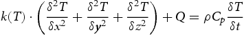
 is the temperature-dependent thermal conductivity of the material; x, y and z are the spatial coordinates; ρ is the density; Cp is the specific heat and Q is the heat source term.
Two independent double-ellipsoidal heat sources were used to apply the heat input in dual-arc AM. A thorough description of the heat source equation and definition of the heat source parameters can be found in reference [12,14,25]. The initial temperature of the substrate and deposition material was assumed to be 300 K. During the AM process, the majority of heat energy is lost to the substrate by conduction. Moreover, heat dissipates due to convection and radiation from the surface of the deposition wall and substrate during the process. Thermal losses due to convection are defined by Newton's law of cooling:
 is the coefficient of convective, and T is the temperature variable. The surface heat loss due to radiation is defined by the Stefan–Boltzmann Law as:
 is the radiation coefficient, and
  is the Stefan–Boltzmann constant
  . Considering the initial temperature, as well as the boundary conditions of convection and radiation, the temporal and spatial distribution of temperature can be calculated by the heat conduction equation. The temperature distribution results were then used to estimate the stresses and distortion in the structural analysis.
A nonlinear mechanical analysis is performed to obtain the mechanical response of the material. Stresses are calculated by the strains generated during the AM process. The strains mainly include elastic strain, thermal strain and plastic strain. Strain induced by the solid-state phase transformation and creep is neglected in the present model. The total strain increment can be expressed as:

Numerical implementation
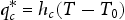
To compare the thermomechanical responses of single-arc and dual-arc parallel additive manufacturing, two finite element models were established. One of them was the thin-walled part fabricated with single-arc AM, and another was two thin-walled parts fabricated with double-arc parallel AM. Schematic representations of the two models are given in Figure 1(a) and (b), separately. The thermomechanical calculations were performed using the FE-based software Abaqus [26]. To accurately consider the effects between the two arcs, the solution domain of the thermal model includes the entire deposition and substrate, instead of using a symmetric model. In dual-arc parallel AM, two arcs travel parallelly to deposit two thin-walled parts with metal addition, keeping a distance of 20 mm perpendicular to the scanning direction, as shown in Figure 1(b). An arc distance of 20 mm is selected by considering the certain size of the arc torch head and process optimization. To keep consistency, substrates with the same dimensions were selected for both models. Thin-walled parts were made up of single-pass ten layers. The scanning length for each layer was 100 mm, and the scanning direction was along the positive Y-direction. The deposition process continued with 20s idle time between layers, and a cooling time of 300s at the end of the deposition.
Schematic representation of the thin-walled parts fabricated using (a) single-arc AM and (b) dual-arc parallel AM. Solution domain of thin-walled parts using (c) single arc AM and (d) dual-arc parallel AM. Line A-A is at the substrate-deposit interface where the stresses and deformation are examined, and point P1 is at the middle of line A-A.
In arc additive manufacturing, the thin-walled parts are formed layer by layer by melting the fed metal wire continuously according to the deposition path. A self-developed user subroutine, DFLUX, in Fortran language was applied to define the heat sources, and the deposition of the metal material can be achieved by sequentially activating a set of elements based on the movement of the heat sources. For the process of dual-arc parallel AM, the starting point and end point of the dual heat sources, as well as the deposition path need to be precisely located. During the deposition process, the substrate was restricted by clamps at the four corners as indicated in Figure 1, which were deactivated after the fabricated part cools down to room temperature. For both models, substrate and deposition wall were made up of Ti6Al4V alloys. Temperature-dependent thermophysical and mechanical properties were considered in the model, and the detailed material properties can be found in our previous research [27]. For the purpose of model validation, a build-up of three-layer, single-pass wall made of Ti6Al4V alloys was also studied.
 is referred to as longitudinal stress and is usually the highest among the stresses of three directions [28]. Moreover, the stresses near the substrate-deposit interface are usually higher than those of other regions, which are primarily responsible for crack propagation and warping [29]. Therefore, longitudinal stresses (y-direction) of the thin-walled parts are carefully discussed in the following part.
Process parameters in this work.

Results and discussions
Model validation
The calculated results from the thermomechanical model are rigorously tested using independent experimental data. Figure 2(a) shows the comparison between the calculated temperature results and the corresponding experimentally measured [30] temperature of a single-track three-layer Ti6Al4V deposit fabricated by DED-Arc. It can be found that both the peak temperature and cooling temperature measured by the two methods are in good agreement. Moreover, stress curve along line B-B are shown in Figure 2(b), which have the same trend of distribution. The slight mismatch between the computed residual stresses and the measured results may be due to the assumptions made in the thermomechanical model and the measurement error. The agreement between them gives us confidence to apply the model to calculate the thermomechanical responses in this work.
Comparison between the experimentally measured [30] and the corresponding numerically computed (a) thermal cycling curves at point P on the top surface of the substrate and (b) residual stresses along x-direction (transverse stresses) along the line BB of a single-track Ti6Al4V deposit. The line BB is on the bottom surface of the substrate. The processing parameters for the simulations are available in the corresponding literature [30].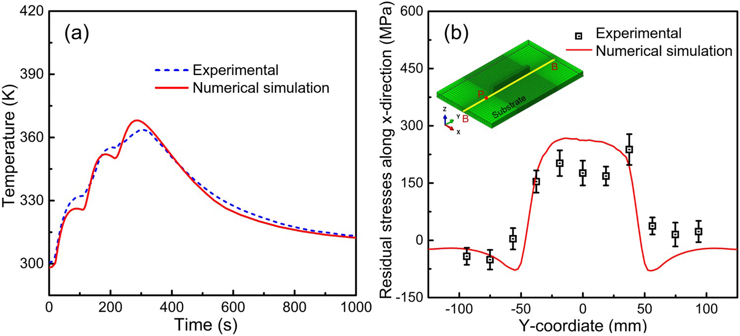
Temperature evolution
The temperature distributions of the thin-walled parts when the heat sources move at the midpoints of 1st, 5th and 10th layers are shown in Figure 3. Figure 3(a–c) and (d–f) show the temperature of the parts fabricated by single-arc and dual-arc parallel AM, respectively. The molten pool is bounded by the liquidus temperature of Ti6Al4V (1928K) and marked in grey in the figure. As the deposition continues layer by layer, the high-temperature region expands quickly during the 1st layer deposition and then increases slightly due to the idle time between layers. Moreover, the molten pool size keeps increasing and then remains stable after the 5th layer deposition.
Temperature distribution of the thin-walled part for single-arc AM when arc moves across the midpoint of the (a) first layer, (b) fifth layer, (c) tenth layer deposition, and temperature distribution of dual-arc parallel AM parts during the deposition of (d) first layer, (e) fifth layer and (f) tenth layer.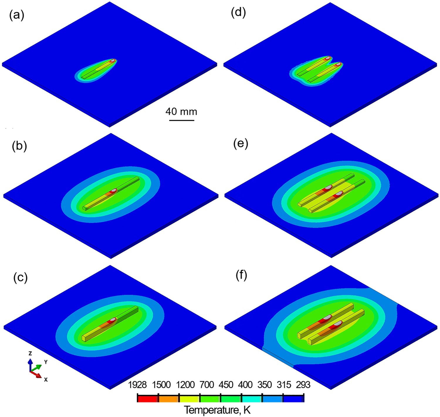
Figure 4(a) shows the temperature history of the midpoint (P1 in Figure 1) of the first layer for both the single-arc and dual-arc thermomechanical models. For both models, the first layer experiences ten thermal cycles. The temperature peaks up quickly when the heat source passes through the midpoint, followed by rapid cooling. By comparing the temperature results of P1 for single-arc and dual-arc AM, peak temperature and trough temperature are higher in dual-arc AM due to the double heat input in the deposition process, which promotes heat accumulation. There are two peak temperatures above the liquidus temperature among the temperature cycles in single-arc AM, which means the first layer remelts during the second thermal cycle. However, P1 experiences remelting for deposition of the second and the third layers in dual-arc AM, leading to more metallurgical bonding strength. The thin-walled parts cool down to approximately room temperature at the end of deposition. The cooling rate of single-arc AM is much faster (about 10%) than that of dual-arc AM as shown in Figure 4(b). With layer increasing, the cooling rate keeps decreasing for both models.
(a) Temperature history of the midpoint of the first layer for the thermomechanical models. (b) Variation of cooling rate between peak temperature and liquidus temperature at the midpoint of each layer during the deposition. (c) Peak temperatures of the midpoint of each layer during the deposition.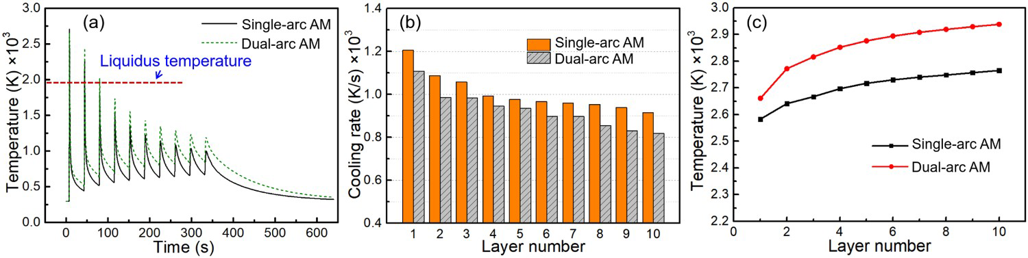
To compare and analyze the thermal accumulation effect with the increasing number of layers, peak temperatures of the midpoint of each layer is shown in Figure 4(c). The trend of peak temperature for each layer is similar for single-arc and dual-arc AM. With layer increasing, the peak temperature increases, and the growth trend becomes steady, indicating more heat energy input into the process than the heat loss from the substrate and the deposition wall.
Stresses and distortions
Figure 5 compares the stress distribution of the thin-walled parts fabricated with single-arc and dual-arc AM. Cutaway isometric views are used to show the accumulations of stresses inside the thin-walled parts. Since the substrate is constrained to shrink by the clamps during the cooling time, high tensile stresses generate throughout the thin-walled part when the deposit contracts, as shown in Figure 5(a) and (c), and the stresses of the part using dual-arc AM are much smaller than those using single-arc AM. This also leads to high compressive stresses in the substrate near the long edge of the part. The stresses of the deposited wall display an alternative pattern marked in orange in Figure 5(d). This is caused by the block-by-block activation simplification in the simulation, where slightly larger stresses generate at the joint of adjacent metal blocks. When the part cools down to room temperature and the clamps are released, stresses throughout the wall are alleviated as shown in Figure 5(b) and (d). However, high tensile stresses still exist near the substrate-deposit interface.
Stress distribution along y-direction (longitudinal stress) of the thin-walled part fabricated using single-arc AM (a) at the end of cooling and (b) when the components have cooled down to room temperature and the clamps are released. Stress distribution along y-direction of the thin-walled parts fabricated using dual-arc AM (c) at the end of cooling and (d) when the components have cooled down to room temperature and the clamps are released.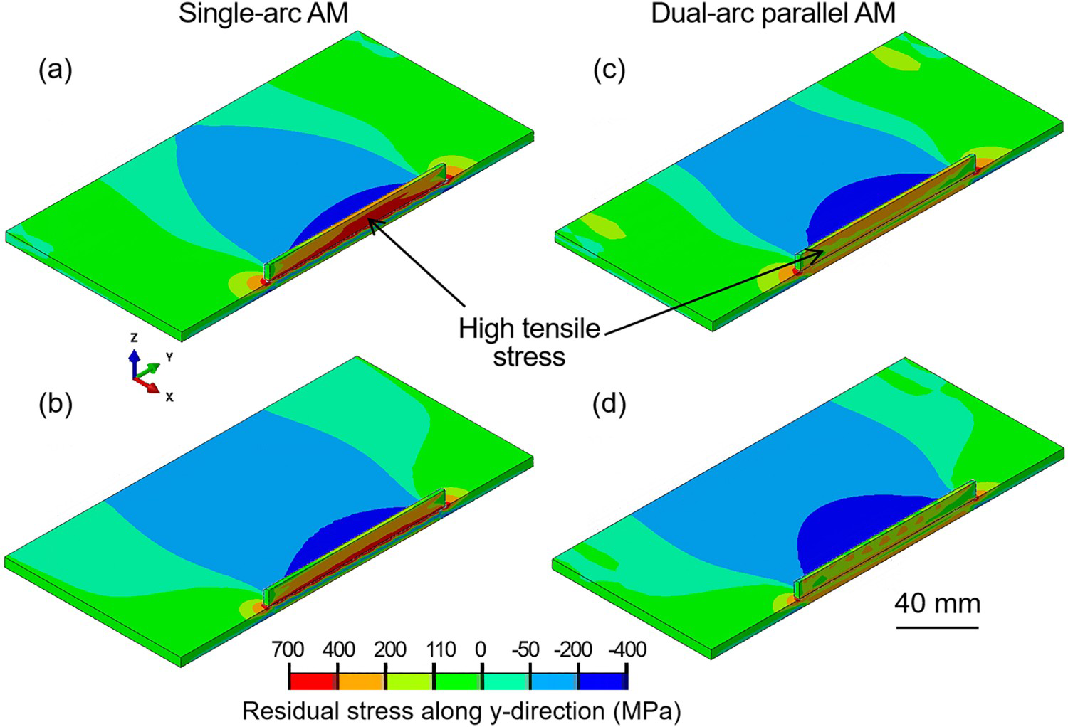
The stresses are compared quantitatively along line A-A (see Figure 1) which is near the substrate-deposit interface as shown in Figure 6. Figure 6(a) and (b) show the variations in y-component of stresses during cooling time for the components fabricated using single-arc and dual-arc AM respectively. It's obvious that tensile stresses exist at the substrate-deposit interface when cooling starts, and the stress values increase a lot at the end of cooling since stresses usually develop during cooling time. Although the trend of stress distribution for single-arc and dual-arc AM is similar, the stress values at the midpoint of substrate-deposit interface have decreased by 53% from 650 MPa for single-arc AM to 300 MPa for dual-arc AM. This is because double heat input is fed parallelly in dual-arc AM while other process parameters remain the same, resulting in homogeneous temperature distributions and a smaller cooling rate of the deposition wall. Moreover, it's interesting to find that two peak stress values exist at the two ends of substrate-deposit interface region for the ten-layer thin-walled part. However, the stresses at the substrate-deposit interface are relatively flat in the single-layer deposition, which is shown in our previous research [28]. This can be attributed to the fact that the two ends of the interface region exhibit higher cooling rate and are subject to greater tensile stress from the substrate during the cooling time. Moreover, the tensile stress values are particularly pronounced with layer increasing.
Calculated y-component of stress distributions along line A-A (indicated in Figure 1) in the parts fabricated using (a) single-arc AM and (b) dual-arc AM. (c) Longitudinal stresses of the midpoint of each layer at the cooling end of each layer.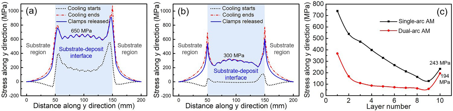
Since stresses are generated gradually during the cooling process, longitudinal stresses at the mid-length of each layer are extracted at the end of cooling for each layer in Figure 6(c). The stresses of the thin-walled part fabricated using dual-arc AM are much smaller during the whole deposition process. The stresses are rather high for the first layer and then decrease gradually as the number of layers increases. The first few layers are in-process stresses when the part remains relatively high temperature, whilst the stresses of the last layer are the residual stress when the part cools to room temperature. At the end of deposition, the stresses of the last layer exhibit about 20% decrease from 243 MPa for single-arc AM to 194 MPa for dual-arc AM.
The vertical deformation of the component primarily determines the warping of the components. Therefore, the deformation distribution along z-direction of the thin-walled parts are analyzed during the deposition process as shown in Figure 7. The substrate can be divided into two parts along the scanning direction, as indicated by N and S in Figure 7. For both models of single-arc and dual-arc parallel AM, the deformation distribution before releasing the clamps is approximately symmetrically distributed about the central section (section C–C) of the deposition track as shown in Figure 7(a) and (c), and the deformation values are relatively small (smaller than 1 mm). This is mainly because the substrate is constrained by the fixtures, causing the substrate and deposition wall cannot be retracted freely during cooling time.
Deformation along z-direction of the thin-walled part fabricated using single-arc AM (a) at the end of cooling and (b) when the components have cooled down to room temperature and the clamps are released. Deformation along z-direction of the thin-walled parts fabricated using dual-arc AM (c) at the end of cooling and (d) when the components have cooled down to room temperature and the clamps are released. Calculated z-component of deformation distributions along line A-A (indicated in Figure 1) in the parts fabricated using (e) single-arc AM and (f) dual-arc AM.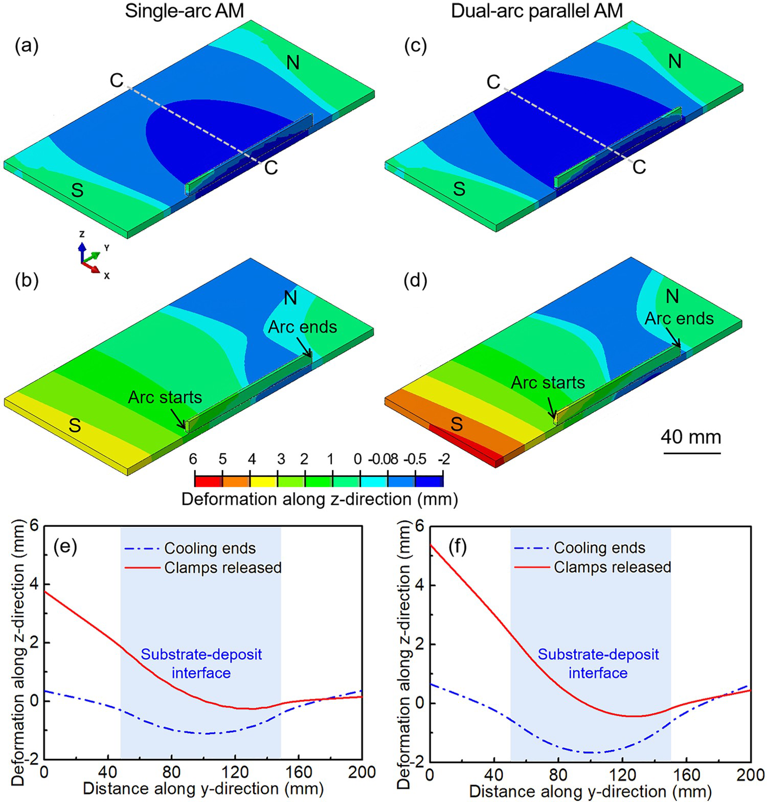
When the clamps are released, the substrate and the deposit start to deform freely, and the deformation of the thin-walled parts fabricated using dual-arc AM is slightly higher (about 1 mm) than that using single-arc AM (see Figure 7(b) and (d)). This is due to the fact that compared with single-arc AM, more heat energy is input in dual-arc AM process, and more region generate plastic deformation and cannot return to the origin state after releasing the clamps, resulting in a slight increase in deformation accordingly. Moreover, the substrate shows uneven deformation distribution along the scanning direction after releasing the clamps. The deformation distributions plotted along line A-A for the parts fabricated using single-arc and dual-arc AM are shown in Figure 7(e) and (f), respectively. It's obvious to find that the deformation of the substrate near side S is much larger compared with side N. The main cause is that each layer was deposited along positive y-direction, and substrate at the S side is close to the arc starting point, which has a high cooling rate in deposition process of each layer, resulting in large deformation. The uneven temperature distribution along the scanning direction becomes pronounced with the layer-by-layer deposition.
Summary and conclusions
In this work, a 3D finite element model with two independent heat sources is developed, validated and utilised for the analysis of thermal behavior and mechanical responses in dual-arc parallel additive manufacturing process. Temperature, stresses and distortion distributions are calculated and compared for both the thin-walled parts fabricated using single-arc and dual-arc AM. The main findings are summarised as follows:
Although the trend of stress distribution for single-arc and dual-arc parallel AM is similar, the stress values at the substrate-deposit interface for dual-arc AM have decreased by 53%. This is because double heat input is fed parallelly in dual-arc AM, resulting in homogeneous temperature distributions and a smaller cooling rate of the deposition wall. For the thin-walled parts fabricated using the single-arc and dual-arc AM, the substrate shows uneven deformation distribution along the scanning direction at the end of deposition. Since high cooling rate generates near the arc starting point of every layer and this effect is pronounced with the layer increasing, the deformation of the substrate near the arc starting point is larger than the other side. The deformation of the substrate in dual-arc parallel AM is larger than that in single-arc AM with slight difference of about 1 mm. This can be attributed to the fact that more heat energy is input in dual-arc AM process and more region generate plastic deformation, which cannot return to the origin state after releasing the clamps.
Footnotes
Acknowledgments
This work was supported in part by the Key Research and Development Program of Jiangsu Province under Grant BE2022069-1 and BE2022069-2, the Natural Science Research Project of Jiangsu Higher Education Institutions under Grant 22KJB460030, Science and Technology Achievement Transformation Project of Jiangsu Province under Grant BA2020004, and the startup funding at the Nanjing Normal University under Grant 184080H202B318.
Disclosure statement
No potential conflict of interest was reported by the author(s).