
Abstract
The achievement of an effective connection between superelastic NiTi and 304 stainless steel (304 SS) using ultrasonic welding with varying welding energy inputs has been studied. It has been observed that the addition of aluminium foil serves to a tight joint, which displays two kinds of interfaces where no defects were observed. With the increase in input energy, the peak load exhibits an initial growth phase followed by a decrement phase, and the interfacial heat production intensifies gradually, leading to subsequent interfacial oxidation. When the input energy is 750 J, the joint peak load reaches its maximum at 890 N. The fracture pattern of the joint exhibited both interfacial fracture and edge fracture. In high welding energy situations, Fe4Al13 (a brittle phase) is produced, which deleteriously impact on the joint's performance. Conversely, low welding energy results in the absence of any brittle phase formation.
Introduction
NiTi alloy, being an exemplar of functional materials, has evoked immense scientific interest due to its exceptional super elasticity and shape memory effect, as well as its exquisite biocompatibility and corrosion resistance [1]. However, this functional superstar has certain limitations. First, it suffers from the curse of expensive production costs when compared to other metals [2,3]. Second, its notorious super elasticity also means that it possesses poor machinability, which only adds insult to injury [4,5]. Lastly, NiTi alloy exhibits extreme sensitivity to heat input, making it a tough nut to crack for researchers looking to make a connection with other materials. As such, the connection between NiTi alloy and other materials has been an area of intense focus for researchers. Perhaps, the most notable example is stainless steel (SS), which is a popular go-to metal in the field of biomedicine, owing to its high-grade biocompatibility, corrosion resistance and superior mechanical properties [6]. The successful realisation of a high-quality connection between NiTi and SS would undoubtedly expand their respective application scopes, allowing them to be used in a diverse array of systems with convoluted geometries. Ultimately, the inherent attributes of two materials can be leveraged to benefit the overall structure of the system [3].
In recent years, researchers have studied on the reliable connection between NiTi and SS. Various fusion welding methods have been explored for the connection between NiTi and SS. [7]. However, the performance of the joints obtained by these methods is relatively poor [7–20] although they choose to add an intermediate layer, such as copper or aluminium, to improve performance [21–24].
Ultrasonic spot welding (USW) is a new welding technology that has been used in industries over the past 20 years, including aviation, medical, microelectronics and automobile manufacturing. Zhang et al. [25] investigated the homogeneous ultrasonic welding of 0.2 mm thick NiTi alloy. Based on that, Li et al. [26] further explored the effect of Al interlayer on the properties of ultrasonic joints of 0.5 mm thick NiTi alloy. However, at present, the research mainly focuses on the influence of ultrasonic welding process parameters on the joint properties and organisation of soft and light metals, as well as the reinforcement of the interlayer (foil, powder and composite interlayer) with the new process of heat-assisted ultrasonic welding, and lacks the research on the ultrasonic welding aspects of cemented carbides. Pure aluminium has a low melting point and a high linear expansion coefficient, which allows it to quickly reach the semi-melted state and fill the gaps between materials to enhance the interface metallurgical bonding [25–31]. During the ultrasonic solid-phase connection process, it is found that a combination of aluminium and NiTi is less likely to produce a brittle phase, while aluminium and SS will not produce an intermetallic compound layer under the condition of moderate welding energy [32,33].
This paper explores a reliable method to connect NiTi/SS, which has significant potential for practical applications. The study provides a detailed analysis of the use of USW for connecting different types of NiTi and SS to an aluminium interlayer.
Materials and method
The base materials (BM) used in this study were superelastic NiTi shape memory alloy (fully austenitic at room temperature) and commercial AISI 304 SS (γ -Fe) sheets, both with a size of 60 mm × 15 mm × 0.15 mm. A pure aluminium foil was used as the middle layer with a size of 15 mm × 15 mm × 0.02 mm, as shown in Figure 1. The chemical composition and mechanical properties of the BM are presented in Table S1 and Table S2, respectively. Before welding, the NiTi alloy sample was soaked in a 7.5% HF, 20% HNO3 and 72.5% H2O (by volume) solution for 1 min to remove the oxide layer. The oxide film on the surface of the 304 SS was removed with 400# sandpaper, then both were cleaned with alcohol and dried. During welding, an 304 SS overlap with NiTi alloy was adopted and the lap area of the two plates is 15mm × 25 mm.
(a) Ultrasonic metal spot welding setup, (b) and (c) pattern and dimensions of the Sonotrode tip and Anvil and (d) configuration diagram of welding.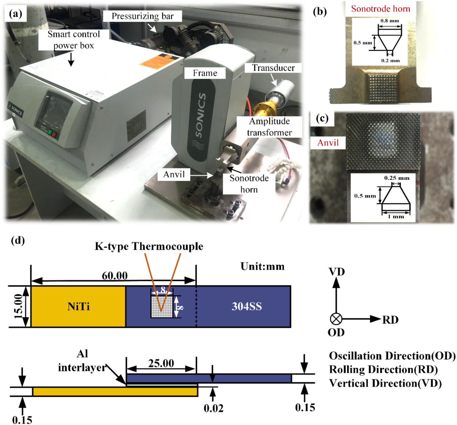
A SONICS ultrasonic welding system (MSC4000-20) was used, as shown in Figure 1(a), which maintained a constant frequency of 20 kHz. Specific parameters are presented in Table S3. The detailed dimensions of the tip and anvil of the sonar pole are illustrated in Figure 1 (b and c). During the welding process, the vibration direction was parallel to the sheet rolling direction. During the USW process, a type-K thermocouple with a diameter of 0.08 mm was embedded at the centre of the weld interface to measure the interface temperature, showed in Figure 1(d). Temperature readings were collected 5 times for each parameter.
The welded joints produced under 250, 750 and 1250 J with a constant weld amplitude of 60 μm and a constant weld pressure of 51 psi were segmented by wire electrical discharge machining along the vibration direction of the weld centre line, and then ground and polished according to the standard metallographic procedure. The macroscopic morphology of the weld and fracture was observed by a digital microscope (VHX-2000C, KEYENCE, Osaka, Japan). The microstructure and element distribution of weld interface and fracture surface were characterised by a scanning microscope (SEM, SU1510, HITACHI, Tokyo, Japan) equipped with energy dispersive spectrometer (EDS). The local deformation behaviour at the NiTi side of the joint was measured using a nanoindenter (Hysitron, Hysitron TI-Premier) with a Berkovick-type diamond tapered indenter. At room temperature, Micro tester 5848 (INSTRON, Norwood, America) was used to conduct the tensile shear test at a rate of 0.5 mm min−1, with the loading direction set perpendicular to the vibration direction. The test for the same parameters was repeated three times, and the average of the failure indicates the mechanical properties. The interfacial phase composition was analysed by X-ray diffraction (XRD, D8 advanced, BRUKER, Karlsruhe, Japan).
Results and discussion
Interfacial thermal cycles measurement
Figure 2 illustrates the temperature variation trend at the interface centre and the surface morphology under different welding energies. At the start of welding, the interface temperature raised rapidly and reached the peak temperature quickly when the energy was applied to the weld zone, after which the temperature dropped rapidly due to the heat dissipation caused by the cooling gas. All of the peak temperatures were lower than the melting point of pure aluminium (660°C) and BM (NiTi and 304 SS, both of which have melting points over 1000℃), whether the energy was 250 J (160.5°C) or 1250 J (615.8°C), which indicates that it is a solid-phase welding process. Compared with other welding methods, such as friction stir welding, the thermal cycle time of USW is shorter [31].
Temperature cycle curves and the surface morphology under different welding energies.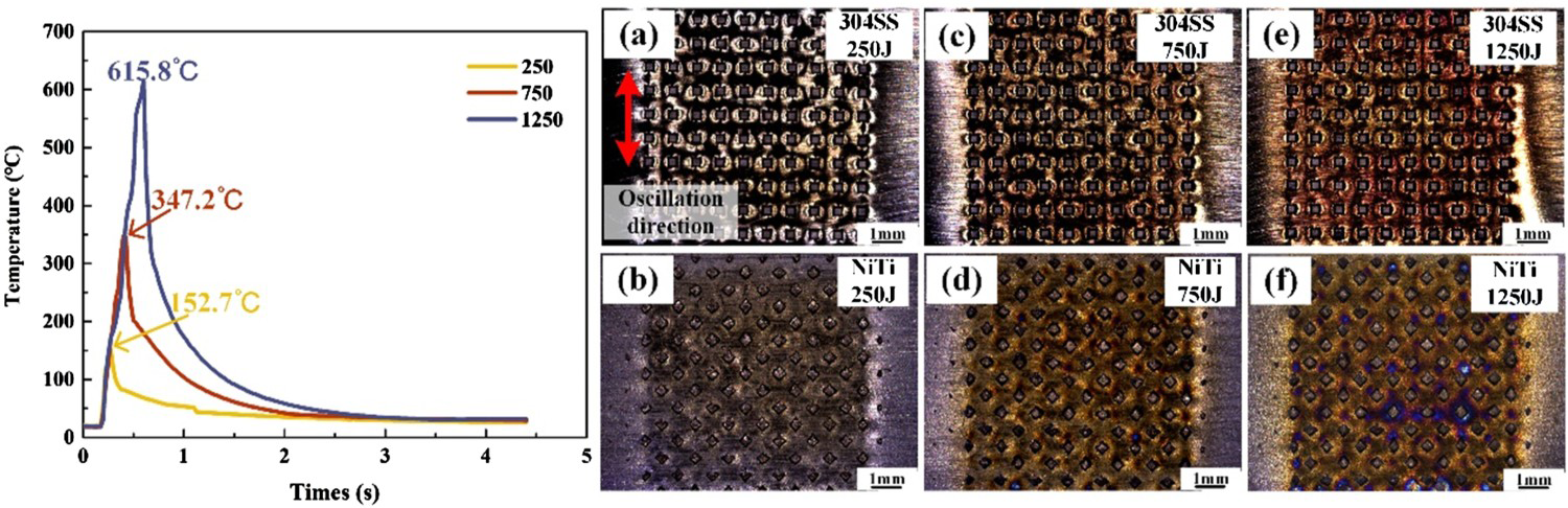
Surface morphology of welds
During the welding process, the normal and shear forces are applied to the workpiece, producing a large stress concentration at the contact convex point and making the workpiece easily undergoing plastic deformation. With the increase in heat input, material softening and micro-connections gradually increase, which is conducive to strengthening joint connections. However, high energy can damage the Al foil and cause joint oxidation in the welding process. Owing to the softening of the material, plastic deformation occurs on the surface of the material under the peak of the sonar pole, resulting in an imprint [34,35]. The surface morphologies of the welds at the Sonotrode tip and Anvil side are shown in Figure 2.
The indentation on both sides is clearly visible after welding, and its shape is consistent with the anvil tip and array mod. The weld surface colour of SS and NiTi gradually deepens as the welding energy increases, indicating an increases in the oxidation of the weld surface. This is because the high-frequency reciprocating friction over an extended period encouraged more plastic deformation and heat, leading to more oxidation (Table S4). In addition, the surface oxidation on the NiTi side is similar to that on the 304 SS side. During USW processing, the tip of the sonar exerts normal pressure on the top of the workpiece (304SS side), causing the workpiece to move at a certain vibration speed. Since the hardness of 304SS is lower than that of NiTi [36], there is less mutual sliding between 304SS and welding joint [37]. Additionally, the TiO2 layer is easily formed on NiTi surface during thermal cycle, which is the most thermodynamically favoured oxide. As the energy got to 1250 J, the colour of the interface changed to violet. Cisse et al. have reported a similar colour evolution of surface oxidation [38].
Microstructure of joint interface
The heat generated by friction during the welding process causes the aluminium foil to semi-melt and fill around the weld teeth, forming the SS–Al–NiTi interface. When the teeth are embedded to a sufficient depth, the SS will directly contact with NiTi, forming the SS–NiTi interface. These two distinct interfaces are shown in Figure 3(a). Figure 3(b) shows the macroscopic feature of the joint interface at different welding energies (250, 750, 1250 J), and provides insights into the relationship between microstructure evolution and joint performance. Indentations on the surface of the sample are evident, and correspond to the tip tooth of the welding tip, where sufficient heat production softens the material and embeds the tip tooth into it. The indentation depth increases from 67 to 120 μm as the welding energy increases from 250 to 1250 J, respectively. As the increased welding energy extends the welding time and generates more heat, leading to increased material softening and deeper indentation. We also observed that there were no voids or unbonded regions in the NiTi-Al-SS joint at different welding energies, indicating that aluminium interlayer effectively improves joint bonding density [36].
(a) Schematic diagram of aluminium foil being extruded and (b) macroscopic morphology of joint interface under 250, 750 and 1250 J welding energy.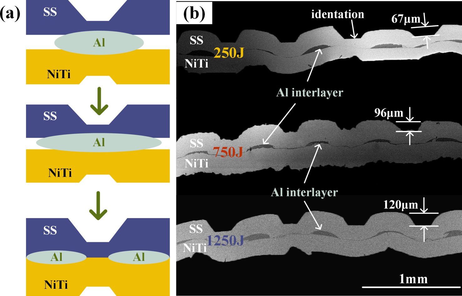
The feature interfaces have different behaviours under different welding energies. The NiTi–SS interfaces are shown in Figure 4(a, c and e). At low welding energy, the interface is relatively smooth, but with the increase in welding energy, the interface becomes distorted. Owing to metallurgical bonding many micro-connections are created. The micro joints are crimped and folded during the extrusion process of the teeth, then wiped out by the shear force, resulting in a wavy and serpentine interface. The meandering interface represents a tight mechanical interlock, which can withstand a large axial load, facilitating the improvement of joint strength [31,39]. The NiTi–Al–SS interfaces are showed in Figure 4(b, d and f).
Interface microstructure of joints and the EDS line scanning under different welding energies: (a) and (b) the joint undergo 250 J sample; (c) and (d) the joint undergo 750 J sample and (e) and (f) the joint undergo 1250 J.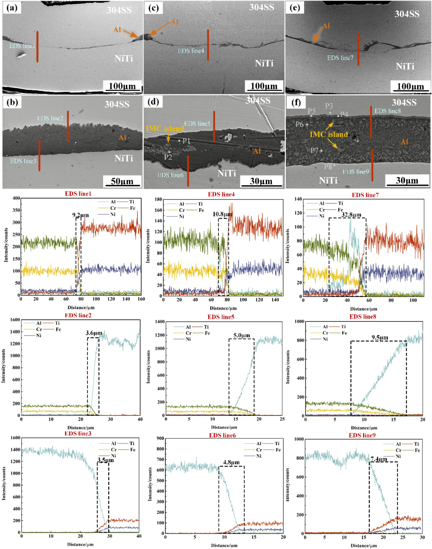
The element distribution at the interface of NiTi–SS, SS–Al and Al–NiTi of the sample in different energy are shown in Figure 4. It can be observed that the element transition at the NiTi–SS interface is abrupt and almost no Al exists due to the fact that aluminium foil could not participate in the diffusion process after being squeezed by the welding tip teeth. Meanwhile, heat generation during the welding process can lead to severe softening of 304 SS, resulting in more plastic deformation [26,30], which will increase in vacancy and dislocation density, then the diffusion distance of aluminium atoms into SS is significantly longer than that of NiTi [33]. As a result, both the NiTi–Al and Al–SS interfaces of the 750 J sample exhibit meandering patterns and can withstand greater axial tensile than the 250 J sample, as shown in Figure 4. When the welding energy reaches 1250 J, both interfaces present a quasi-planar shape. This is because the convex teeth of the sinuous interface are broken off by the shear force generated during the long welding time, and enter the aluminium intermediate layer. Broken base metal and a tiny second phase are also present in the interlayer of aluminium.
The interfacial diffusion layer thickness in different energies are measured and the diffusion layer thickness of Al–SS increases gradually with the increase in welding energy.
Joints performance and failure analysis
Figure 5(a) shows the peak tensile loads of joints at different welding energies. A maximum of 890 N is achieved at 750 J, but the tensile properties deteriorate with further increases in energy. In addition, the increase in welding energy causes changes in the joint fracture mode. At 250 J and 1250 J, the joint exhibits an interface fracture mode, while at 500 J–1000 J, the joint displays weld edge fracture, as illustrated in Figure 5. The joint's mechanical properties, fracture mode and interfaces’ mechanical interlock degree are closely related to atomic diffusion distance. When welding energy is small (250 J), the microstructure of the joint shows that only one interface (Al–SS interface) meanders with shorter element diffusion distances on either side of the interface (Figure 6). Hence, the joint's mechanical interlock and metallurgy combined are weaker. However, when the welding energy is too high (1250 J), the interfaces on both sides are almost planer and the thicker Fe4Al13 brittle phase damages the joint performance. The best joint performance is obtained when the welding energy is moderate (500 J–1000 J), with high mechanical interlocking degree of the interface, long element diffusion distance and no continuous brittle phase present.
(a)Tensile peak loads of NiTi-Al-SS joints under different welding energies and the macrofracture (NiTi side), (b) the nanoindentation curve of NiTi side of the joint and NiTi alloy BM with a welding energy of 750 J. SEM results of fracture of sample 250 J: (a) macroscopic fracture of SS side; (b) the local enlargement in (a); (c) the local enlargement in (b); (d) macroscopic fracture of NiTi side; (e) the local enlargement in (d) and (f) the local enlargement in (e).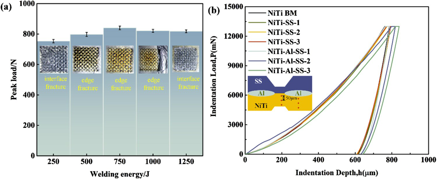
To investigate the effect of ultrasonic welding process and aluminium interlayer on the superelastic deformation properties of NiTi alloy, the NiTi side of the joint was tested using nanoindentation and compared with the original NiTi alloy BM, the results are shown in Figure 5(b): the load displacement curves of the six positions on the NiTi side of the joint are basically consistent, and the deformation behaviour is very similar to that of the BM. Indicating that ultrasonic welding has less impact on the functional properties of the NiTi alloy, the NiTi alloy is able to maintain the same functional properties as the BM after ultrasonic welding.
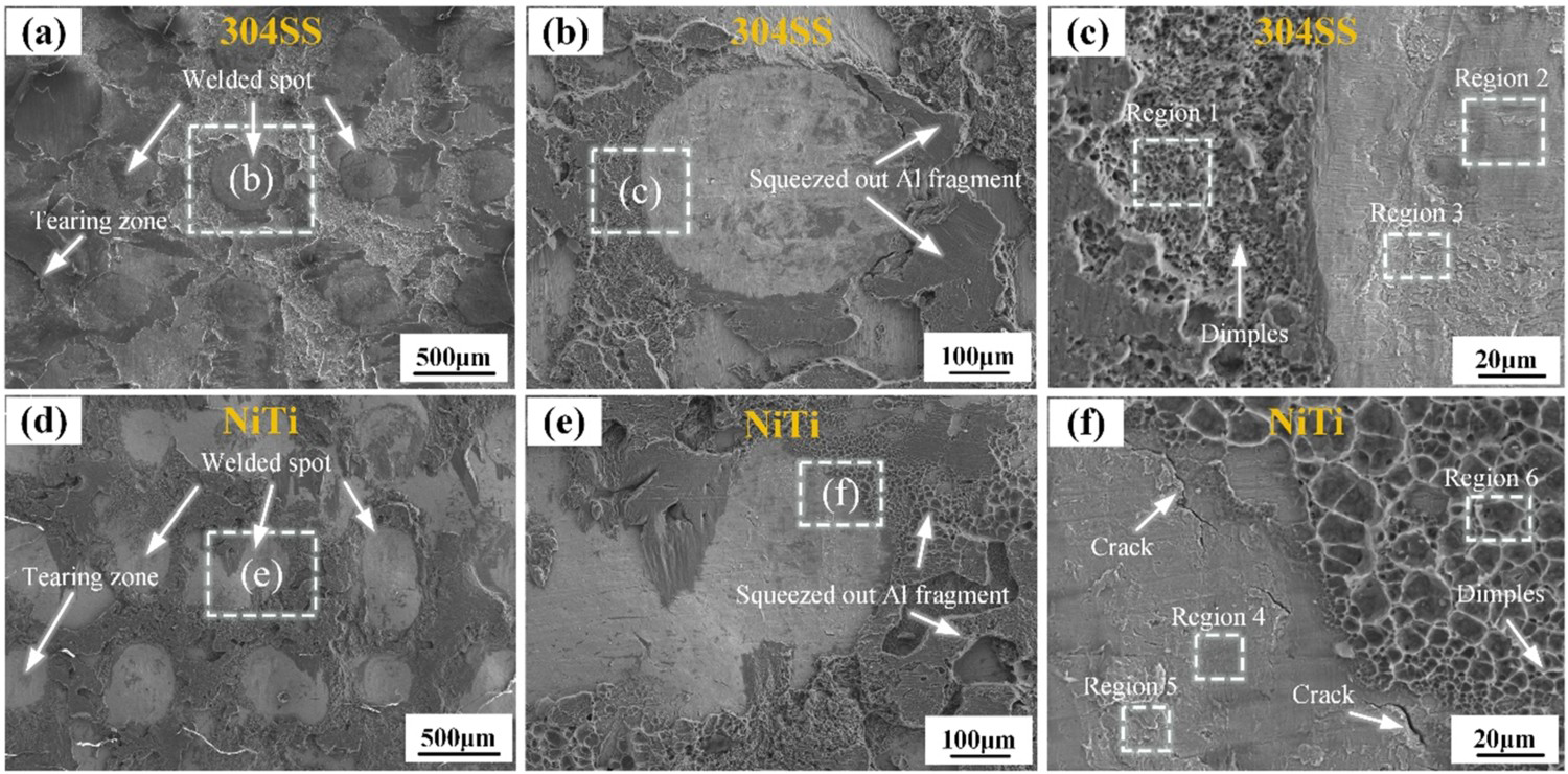
Figure 6 shows the microstructure of fracture in 250 J and the fracture characteristics can be divided into solder spot zone and tear zone. Figure 6 (b and e) is amplified by the solder spot zone, which shows the solder joint centre area is relatively flat, and aluminium exists on the edge of the solder joint extruded by the welding head. The aluminium foil fills the solder joint edge, produce a brazing effect, which can increase the strength of the solder joint edge area effectively and reduce stress concentration [38,40]. The local magnification results of the edge of the welding spot show that the fracture characteristics of the two sides of the welding spot are obviously different. There are dimples of different sizes on the aluminium side, indicating a ductile fracture mode, while lamellar tissue and a plane-like region in the centre of the welding spot, indicating a brittle fracture mode. In Figure 6(f), cracks of varying lengths exist in NiTi at solder joint edge, which may be fatigue cracks. By comparing the fracture characteristics on both sides of the edge of the solder joint area, the deformation mismatch between the solder joint area and the outer area of the solder joint is identified as the main cause of fracture during stretching, resulting in stress concentration, crack and eventual fracture. EDS area analysis was conducted on the edges and parts of the centre of the solder joint, as shown in Table S5. The EDS results show that only Al exists outside the solder joint region with dimple characteristics, indicating a lack of material mixing, while multiple elements exist in the solder joint region. This indicates that under the action of high-frequency loads, materials in the solder joint region mix and eventually form a bond.
Figure 7(a–f) shows the tensile fracture of the sample at 1250 J. It can be seen that there are obvious lamellar and ridge-like structures in the solder joint area, indicating that the solder joint area is a brittle fracture mode. However, there is no dimple at the edge of solder joint, indicating that the joint exhibited apparent brittle fracture characteristics under tensile stress. EDS line scanning results show that there is material mixing in the solder joint area, and the analysis results are consistent with tensile test results.
SEM results of 1250 J sample: (a) macroscopic fracture of SS side; (b) the local enlargement in (a); (c) the result of EDS in (b); (d) macroscopic fracture of NiTi side; (e) the local enlargement in (d) and (f) the result of EDS in (e).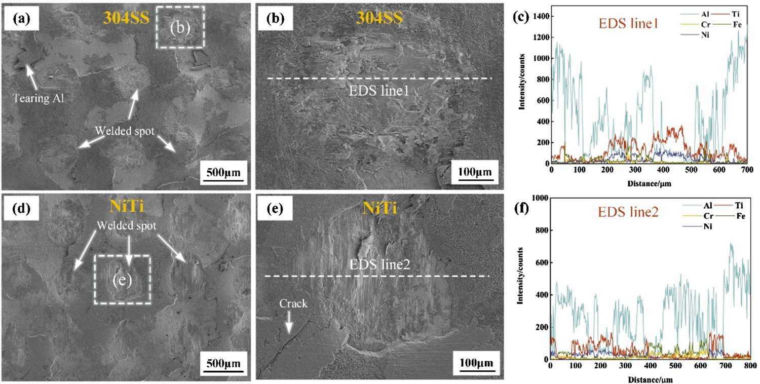
The results of Figure 8(a and b) XRD show that only NiTi, γ-Fe (SS) and Al exist in the fracture of the 250 J. But there is an additional phase in the fracture of the 1250 J, a small amount of Fe4Al13 is detected, which is consistent with the results of EDS analysis. In ultrasonic welding, the lower (250 J) the welding energy, the shorter the welding time and the less of the interface heat generation, making it more difficult to produce intermetallic compounds. When welding energy is increased (1250 J), the interface heat generation and the peak temperature increase. Meanwhile, the plastic deformation with the high strain rate in the welding process significantly enhances the atomic diffusion on both sides of the interface, resulting in the formation of Fe4Al13.
XRD results of fracture of NiTi-Al-SS joint: (a) energy is 250 J and (b) energy is 1250 J.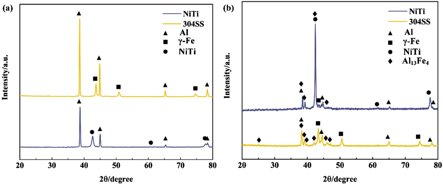
Conclusion
In this study, NiTi alloy was joined to 304 SS with Al interlayer using various welding energy inputs by the USW process, the influence of welding energy on mechanical properties and microstructure of joint was studied, and the following conclusions were obtained.
The present study endeavours to join NiTi alloy to 304 SS with Al interlayer using varied welding energy inputs by the USW process. The goal is to research the impact of welding energy on mechanical properties and microstructure of the joint, ultimately obtaining the following conclusions:
The pure aluminium foil measuring 20 μm was cherry-picked as the middle layer for ultrasonic welding, which enabled the consummation of an effective connection between SS and NiTi. The plastic flow of the interlayer of aluminium generates the beguiling ‘double interface’ characteristics of NiTi-SS and NiTi-Al-SS. It should be noted that when welding energy is maintained at a moderate level, the ‘island’ Fe4Al13 intermetallic compound makes its presence felt at the interface. However, when welding energy is cranked up too high, the interfacial Fe4Al13 intermetallic compound layer is generated, thereby inflicting irreparable damage to the joint's performance. The tensile fracture shows two discernible fracture modes: interfacial fracture and edge fracture, with the peak load of 890 N being obtained at 750 J. Remarkably, NiTi alloy maintains the same functional properties as the BM even after ultrasonic welding, ultimately auguring well for the wider application of this technology across multifarious systems.
Footnotes
Disclosure statement
No potential conflict of interest was reported by the author(s).