
Abstract
Laser metal deposition process was introduced to join AlSi10Mg alloys fabricated by powder bed fusion-laser beam/metal to improve the tensile strength of laser welded joints. The size and the porosity of the hydrogen pores in the weld seam are significantly reduced by laser metal deposition welding. The ultimate tensile strength of the welded joint by using laser metal deposition reaches 318.8 MPa, and the microhardness of the weld seam ranges from 99.5 to 105.4 HV. Compared with single-pass welding, the ultimate tensile strength and hardness are increased by 60.6% and 27.6%. This is mainly attributed to the reduced porosity, refined α-Al structures and increased connectivity of the Si-rich networks of the weld seam achieved by laser metal deposition welding.
Introduction
Powder bed fusion laser beam/metal (PBF-LB/M) process, is one of the most commonly used metal additive manufacturing (AM) technologies. In recent years, there has been a high demand for AlSi10Mg alloys fabricated by PBF-LB/M in the aerospace, automotive and thermal management industries. This is mainly due to their excellent printability, strength-to-weight ratio and high mechanical properties [1]. However, the size of AlSi10Mg parts fabricated by PBF-LB/M has been limited by the available dimensions of the building chamber, because the larger part requires a large build chamber with high investment and operational costs due to a large number of feedstock powders [2]. To solve the size limitation, welding technologies have been used to join PBF-LB/M parts to each other or conventionally manufactured materials [3]. Furthermore, repairing PBF-LB/M components through welding is more cost-effective and time-saving than replacing them, making welding of PBF-LB/M parts a practical solution for further applications [4]. Until now, some efforts have been devoted to developing joining techniques for the AlSi10Mg alloys fabricated by PBF-LB/M, for instance, tungsten inert gas welding [3], cold metal transfer welding [5], electron beam welding [6,7], laser welding [2,8] and friction stir welding [9,10]. However, it is very challenging to fusion welding of AlSi10Mg alloys fabricated by PBF-LB/M due to the reduced joint performance and high susceptibility to hydrogen pores [3]. More recently, tremendous efforts have been conducted to weld of AlSi10Mg alloys fabricated by PBF-LB/M with introducing high-pressure and high-vacuum environments during the welding process [11,12]. Nevertheless, the hydrogen pores are still not significantly reduced maintaining the initial high strength of the base metal (BM). As known, the excessive porosity will reduce the load-bearing area of the cross-section, leading to local stress concentration and accelerated crack propagation, thus decreasing strength and ductility [13]. Therefore, it is important that a new welding solution to reduce porosity of the weld seam be explored for AlSi10Mg alloys fabricated by PBF-LB/M.
Laser metal deposition (LMD) process, one of the laser-directed energy deposition (L-DED) manufacturing processes, offers a variety of advantages, for instance, lower heat input, lower dilution ratio and excellent mechanical properties than the single-pass laser welding [14], which usually has been used for repair and remanufacturing in industry. Recently, LMD process has been introduced for joining some materials that are difficult to be welded with conventional welding techniques. Mudge and Wald [15] joined two completely incompatible alloys through layer-by-layer accumulation of LMD welding using functional gradient materials with altered filler material's chemical compositions. Lei et al. successfully joined Sip/6063Al composite [16] and dissimilar Ti/Al butt joints [17] using LMD welding. Results from these studies suggest that it is feasible to join materials through LMD welding. However, study on welding of AM materials with LMD welding remains limited. In our preliminary study, the porosity in the weld seam in AlSi10Mg alloys fabricated by PBF-LB/M has been largely reduced using LMD welding [2]. However, the effect of LMD welding on the porosity, microstructure and mechanical properties has not been studied yet, and the joint softening phenomena of welded joints is still far from being completely understood in AlSi10Mg alloys fabricated by PBF-LB/M.
In this study, a novel LMD welding method was introduced to join of AlSi10Mg alloys fabricated by PBF-LB/M of 3.0 mm in thickness. The influence of the LMD welding on the weld shape, pore characteristics, microstructure, hardness and tensile properties of welded joints was investigated and compared with those of single-pass laser welding.
Experimental
The BM specimens used for welding were in the dimension of 55 × 80 × 3 mm, fabricated with a commercial EOS M280 machine in a high-purity argon protection environment (99.9999%). During the PBF-LB/M processing, the raw gas-atomized AlSi10Mg powders with a size ranging from 15 to 53 μm were deposited on an Al substrate, which was pre-heated to 150°C. The oxygen content of less than 200 ppm was kept under the argon gas protection. The laser scanning path of each layer was rotated 67° from the path of the previous layers. The process parameters were optimised by the orthogonal experiment for achieving a high relative density. The relative density of as-built AlSi10Mg samples was estimated by Image method using the Image J software. The samples with a relative density higher than 99.6% were selected for welding. Considering that PBF-LB/M Al alloys produced with optimised parameters can achieve relative density that exceeds 99%, the AlSi10Mg alloys fabricated by PBF-LB/M prepared in this study have a comparatively high relative density. The optimum processes were a laser power of 370 W, a scanning speed of 1300 mm/s, a hatching space of 0.19 mm and a layer thickness of 20 μm. Before welding, the surface of welding specimens without heat treatment was chemically cleaned to ensure a smooth and pollutant-free surface by removing the oxide film.
Figure 1(a) and 1(b) clearly show the macrostructure of the AlSi10Mg alloys fabricated by PBF-LB/M in the side view at the XZ plane and YZ plane parallel to the processing direction, exhibiting a typical ‘fish-scale’ pattern of the melt pools. However, the melt pools in the top view at the XY plane perpendicular to the processing direction (Figure 1(a) and 1(c)) exhibit elliptical morphology with a width of approximately 100-200 μm controlled by layer thickness and scan strategy. High magnification scanning electron microscope (SEM) micrograph shown in Figure 1(d) clearly differentiates three zones for the melt pool structure according to the morphology and size of the Si-rich eutectic regardless of observation planes: a coarse cellular zone (CCZ) composed of coarse α-Al grains and the interconnected Si-rich eutectic with thick and large networks, a fine cellular zone (FCZ) characterised by fine Si- rich phases, and a heat affected zone (HAZ) between the CCZ and the FCZ. The feature of the BM microstructure is consistent with the previous studies [18,19]. The Si-rich eutectic of the BM microstructures presents interconnected cellular network morphology homogenously distributed in the dark Al matrix, as seen in Figure 1(e).
Macrostructure and microstructure of the AlSi10Mg alloys fabricated by PBF-LB/M: (a) Three-dimension; (b) XZ plane; (c) XY plane; (d) High magnification micrograph in the XY plane; (e) High magnification micrograph of fine cellular zone.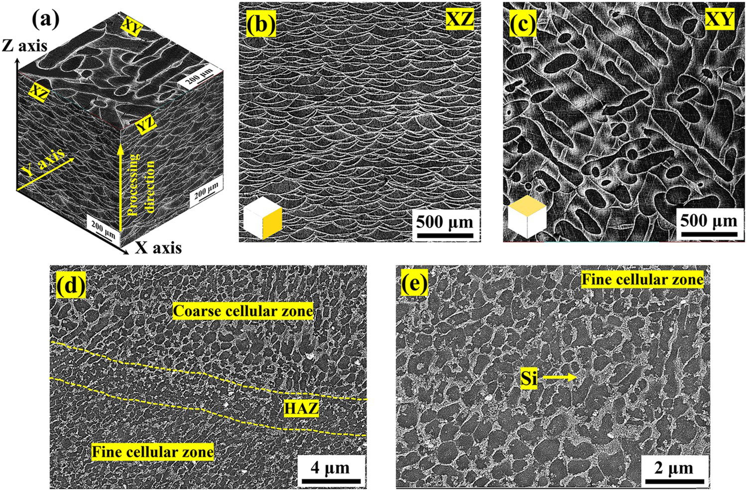
For comparison, single-pass welding with filler powders and LMD welding of the AlSi10Mg alloys fabricated by PBF-LB/M were carried out. The two welding processes were conducted using a TruDisk 4001 YLR-4000 fibre laser with a wavelength of 1030 nm in combination with a KUKA KR 90 R2900 Robot (KUKA, Germany). The transmission core diameter of the fibre was 600 μm, focal length of the collimating lens was 200 mm and focal length of the focused lens was 100 mm. During the welding, commercially gas-atomized AlSi10Mg powders with 45∼105 μm in size were selected as filler powders. A laser welding head was mounted on an ABB 6-axis robot with a DPSF-2 automatic powder feeder. The SO16 (Trumpf) laser powder feeding coaxial nozzle can feed powder in three axes. The schematic diagram of the LMD welding setups and the deposition passes for the weld seam is illustrated in Figure 2. As seen in Figure 2, the welding specimens were prepared in a 45° V-groove configuration with a 0.5 mm root face and 0.1 mm root gap. The weld seam of LMD welding is composed of 22 passes, which is designed as two sub-regions, e.g., bottom-pass (the first pass) region and upper-pass (the left 21-passes) region. The welding processes of single-pass welding and LMD welding shown in Table 1 were optimised based on the preliminary welding trials.
The LMD welding setups for AlSi10Mg alloys fabricated by PBF-LB/M. The welding processes for AlSi10Mg alloys fabricated by PBF-LB/M.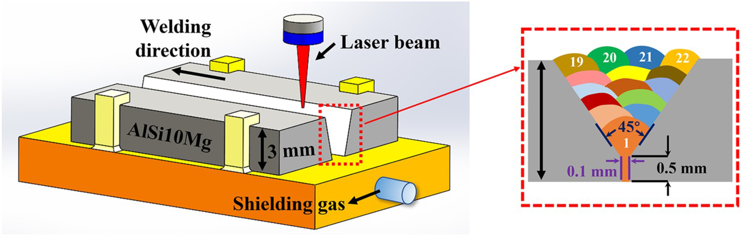
For the single-pass welding, the diameter of the focus spot was approximately 0.4 mm, and a laser power of 2000 W, a welding speed of 1.2 m/min and a powder feeding rate of 3.15 g/min were kept constant to obtain a full penetration weld seam, with a flow rate of 99.99% pure argon of 10 L/min for both the front and back surfaces, and 5 L/min for the powder carrier. For the LMD welding, the shielding gas used for the powder carrier and the weld pool was also 99.99% pure argon, with the velocity of 2.5 L/min and 30.0 L/min. The AlSi10Mg powders were uniformly fed into the groove, melted and built the weld seam under the conditions of a laser power of 1500 W, a focus spot diameter of 2.2 mm, and a powder feeding rate of 2.7 g/min. The welding speed was 1.2 m/min and 2.4 m/min for the bottom-pass region and the upper-pass region, respectively. Linear heat input (LHI) of the two welding processes can be defined as the laser energy absorbed per unit length of time [18,20], which can be calculated according to the Equation (1):

The macrostructures of the welded joints were examined using an Olympus LEXT OLS4100 laser scanning microscope. The microstructure of different regions of the welded joints was investigated using a QUANTA FEG 650 and a Gemini SEM 300 equipped with a NordlysNano Electron Backscatter Diffraction (EBSD) system. Microhardness measurements were taken using a Vickers diamond indenter with an applied load of 100 g. Uniaxial tensile tests were performed at room temperature using a universal tensile testing machine (CMT 5205 GL) with a cross-head speed of 2 mm/min. In addition, strain was measured using a contact-type extensometer. Rectangular tension test specimens were prepared with sub-sized dimensions, and the tensile properties of the welded joints were calculated based on the average results of three tensile tests.
Results and discussion
Weld morphology and pores
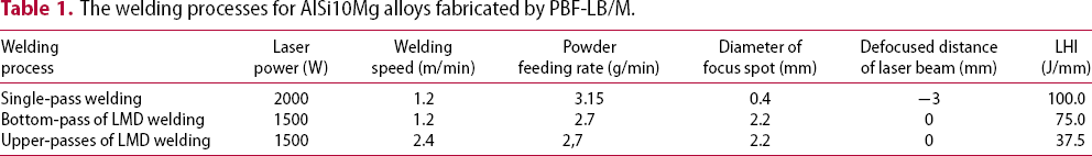
The cross sections of welded joints produced by single-pass and LMD welding in AlSi10Mg alloys fabricated by PBF-LB/M are presented in Figure 3(a–c). It can be seen that a full penetration weld without obvious cracking defects is obtained for both welded joints. The single-pass welded joint displays an ‘hourglass’ shape, indicating a typical keyhole mode. However, large spherical hydrogen pores are clearly observed in the upper part of the weld seam, and a large number of small hydrogen pores are evenly distributed in the remaining region of the weld seam as shown in Figure 3(a). The total porosity of the weld seam is 14.3% and the maximum size of the pores is 498.5 μm in diameter. For the LMD welded joint, the weld seam consists of two distinct regions: the bottom part (produced by the first pass) and the upper part (produced by the remaining 21 passes). In contrast to single-pass welding, the weld seam of the upper part has shallow penetration and large width. The porosity of the weld seam in the LMD welded joint is significantly decreased to 1.7%, and the maximum size of the pores is also lowered to 171.3 μm. Therefore, the porosity and pore size of the weld seam in AlSi10Mg alloys fabricated by PBF-LB/M are effectively reduced by using LMD welding compared to single-pass welding. As mentioned earlier, the heat input of single-pass and LMD welding is 100.0 J/mm and 37.5 J/mm, respectively. It is obvious that the heat input of LMD welding is remarkably reduced compared to single-pass welding. Additionally, the LMD welding leads to an increased time for cooling between the single tracks. Thus, both the lower heat input and the increased time for cooling between the single tracks for LMD welding result in a smaller fusion area of the BM, leading to less hydrogen entering the weld pools. This is the reason why the LMD welding significantly reduces the porosity and the size of the hydrogen pores generated in the weld seam of AlSi10Mg alloys fabricated by PBF-LB/M.
Macrostructure and pore characteristics of welded joints: (a) Single-pass welding; (b) LMD welding; (c) Comparison of pore size and porosity.
Mechanical performance of the joints
Figure 4(a) shows the microhardness distribution of welded joints produced by single-pass and LMD welding. It can be seen that the BM has an average microhardness value of 143.0 HV. The microhardness in the weld seam for the LMD and single-pass welding is in the range of 99.5∼105.4 HV and 66.2∼91.9 HV, respectively. This indicates that the hardness in the weld seam is lower than that of the BM, implying a softening phenomenon occurred in the weld seam. However, the weld seam of LMD welding shows an increase of ∼27.6% in microhardness compared to single-pass welding. Additionally, the LMD welded joint produces a narrower heat-affected zone (HAZ) than that of the single-pass welding, indicating a narrower softening zone in the welded joint.
(a) Comparison of microhardness distribution between two joints; (b) Stress-strain curves of single-pass and LMD welded joints; Fractured tensile specimens of (c) single-pass and (g) LMD joints; Fractured path of (d) single-pass and (h) LMD joints; (e) Fracture surface in single-pass welding; (f) High magnified micrograph marked in (e); (i) Fracture surface in LMD welding; (j) High magnified micrograph marked in (i).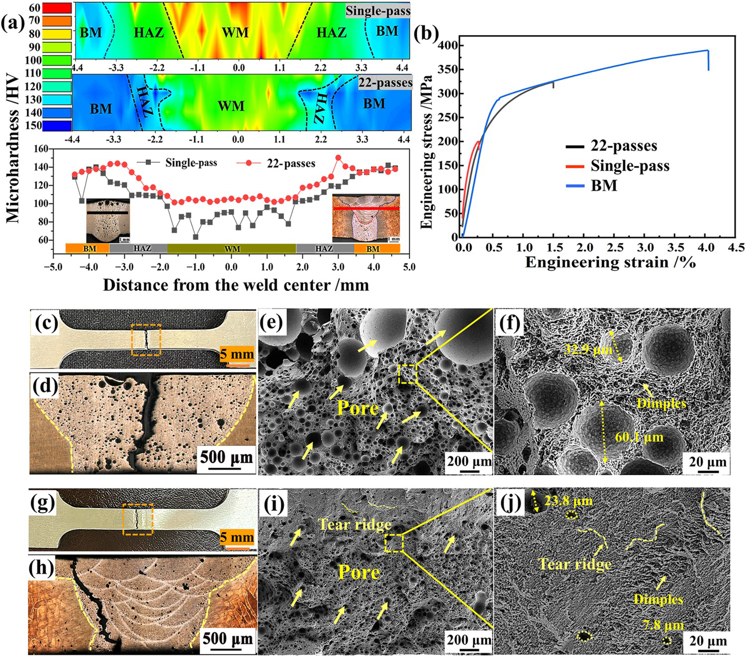
Figure 4(b) illustrates the stress-strain curves of the welded joints as well as the BM. The ultimate tensile strength (UTS) is 389.7 MPa, 318.8 MPa and 198.5 MPa, and an elongation index (EI) is 4.50%, 2.53% and 0.67%, for the BM, LMD joints and single-pass joints, respectively. Thus, the tensile strength of the welded joints is obviously lower than that of the BM, which is consistent with the hardness trend. Nevertheless, the UTS of LMD joints is significantly increased by 60.6% compared with that of the single-pass welding. Specially, the EI of the LMD welded joint is also higher than that of the single-pass welding, meaning high strength in combination with high ductility is obtained by LMD welding. The macrographs of the fractured tensile specimens and fracture path of the single-pass and LMD joints are depicted in Figure 4(c) and 4(d), Figure 4(g) and 4(h), respectively. It can be seen that both welded joints are without obvious necking fracture at the weld seam, which is probably due to the lowest hardness in this region for the joints. This causes local deformation in this area resulting in a high-stress concentration. However, the fracture location in the weld seam is obviously different for the two joints. The path of the single-pass joint in Figure 4(d) indicates that the fracture mainly occurs at the weld centre with a relatively smooth path perpendicular to the direction of the tensile load. However, the fracture of the LMD joint occurs at the weld seam close to the fusion boundary, and the crack path is close to 45° with respect to the tensile load along the boundaries of the melting pools. This fracture path of the LMD joint increases the resistance of crack propagation effectively, enhancing its mechanical strength of the welded joint. Figure 4(e) displays the fracture surface of the single-pass joint filled with substantial spherical hydrogen pores of 20.1∼766.7 μm in diameter. Additionally, the hydrogen pores in the upper part of the fracture surface are larger than those of the lower part. The reason is likely that the bubbles in the molten pool are easily prone to coalescence and grow up in the floating process [21]. A high magnification micrograph of the fracture surface in Figure 4(f) reveals the small-sized spherical pores are less than 60.1 µm in diameter, and the dimples are also observed in some areas. Thus, the fracture mode of the single-pass welded joint indicates a ductile as well as a brittle failure. The morphology of the fracture surface of the LMD joint is shown in Figure 4(i) and 4(j), which is different from that of the single-pass welding. A largely decreased porosity and size of hydrogen pores and increased dimples are clearly observed on the fracture surface. Figure 4(j) displays that the fracture surface consists of a large number of elongated dimples and tearing edges, exhibiting characteristics of complex dimple-brittle fracture mode. The dimples on the fracture surface of the LMD joint are finer and denser compared to single-pass welding, indicating a relatively ductile fracture.
Si-rich eutectic of weld seam microstructures
The BM reveals homogenously continuous Si-rich eutectic networks with high connectivity in the Al matrix [2], surrounding the α-Al cells with a size of ∼0.5 μm. Thus, the morphology of the Si-rich eutectic in the weld seam produced by single-pass and LMD welding was firstly investigated and compared in this study, as shown in Figure 5.
SEM microstructure of cellular structures of the centre in weld seam: (a) Single-pass welding; (b) LMD welding; Eutectic Si morphology of the weld seam microstructure: (c) Single-pass welding; (d) LMD welding.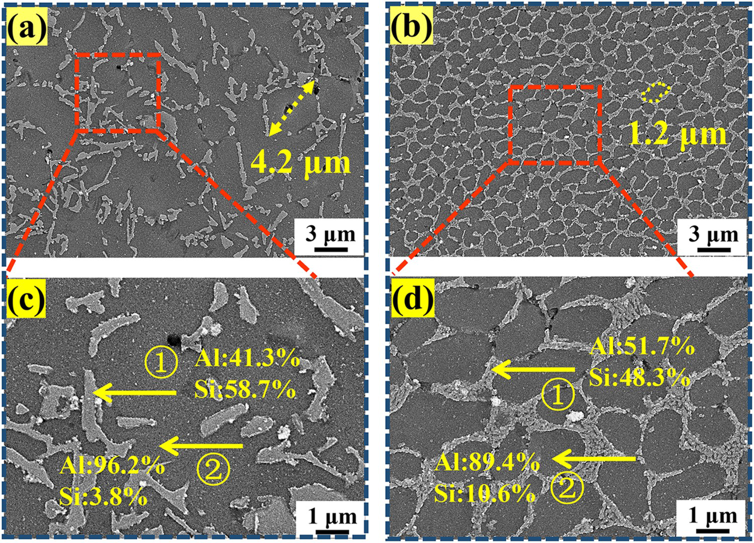
A noticeably different morphology of Si-rich eutectic networks was observed in the two welded joints. For the single-pass welding, the Si-rich cellular networks are completely broken down (Figure 5(a)), which are transformed into the needle or rod shape in the Al matrix. However, the weld seam of the LMD joint presents nearly interconnected Si-rich cellular networks (Figure 5(b)), which are mostly enclosed by the α-Al cells in the matrix as the BM. Moreover, the average size of α-Al cells in the single-pass and LMD weld seam is about 4.2 μm and 1.2 μm, respectively, indicating a significant refinement of α-Al cells in the weld seam of the LMD joint. EDS analysis of the Al matrix (Figure 5(c)) shows a low Si content of 3.8 wt-% in the weld seam produced by single-pass welding, whereas the LMD weld seam (Figure 5(d)) has relatively high Si content of 9.6 wt-%, nearly close to the equilibrium Si content (∼10.0 wt-%) for the BM. Thus, the solid solution strengthening coming from the Si element in the Al matrix within the LMD weld seam is better than that of the single-pass welding, which is beneficial to improving tensile strength and hardness [22,23].
α-Al grain structure evolution
The evolution of α-Al grain structures of the weld seam in the single-pass and LMD joints was investigated using EBSD technique. Inverse pole figure (IPF) maps from the samples selected at the yellow squares marked with ‘1’ and ‘2’ in Figure 3(a) and 3(b) are presented in Figure 6(a) and 6(f). The hydrogen pores with black spheroids are clearly observed in the weld seam of the two joints. However, the pore size and the porosity of the weld seam in the LMD joint are obviously reduced compared to the single-pass joint. It can be seen that the columnar grains are predominant in the single-pass weld seam. In contrast, the microstructure of the weld seam in the LMD joint is composed of finer elongated and equiaxed grains. The average grain size in the weld seam of single-pass and LMD joint is 33.8 μm and 19.7 μm, and the aspect ratio of grains is in the range of 3.9∼11.7 and 1.9∼4.7, respectively, as seen in Figure 6(a) and 6(h). Therefore, LMD welding significantly refines the microstructure of the weld seam compared to single-pass welding.
EBSD IPF mapping in weld seam: (a) Single-pass welding; (f) LMD welding; KAM maps: (b) Single-pass welding; (g) LMD welding; Distribution of grain sizes: (c) Single-pass welding; (h) LMD welding; KAM distribution histograms: (d) Single-pass welding; (i) LMD welding; Distribution of grain boundary misorientation angle: (e) Single-pass welding; (k) LMD welding.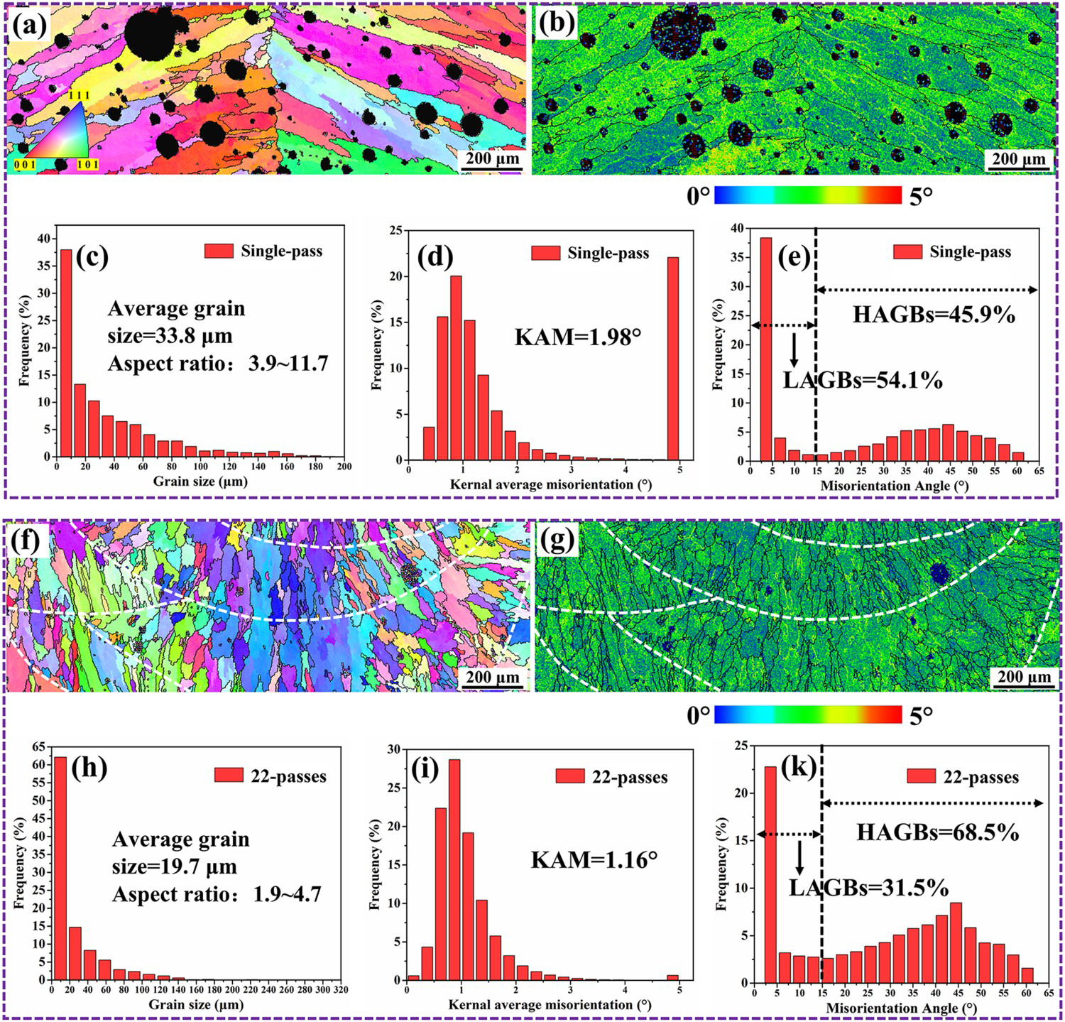
The kernel average misorientation (KAM) angle maps of the weld seam in the single- pass and LMD joint are plotted in Figure 6(b) and 6(g), respectively. It can be seen that the single-pass weld seam represents a non-uniform microstructure, where the KAM values of the regions near the hydrogen pores are higher than those without pores. This is because a stress field (similar to strain misfit) is generated around these regions. However, the KAM distribution in the weld seam of LMD joints is more uniform due to the formation of finer pores and decreased porosity [24]. KAM histograms of the weld seam in the single-pass and LMD joints are presented in Figure 6(d) and 6(i), respectively. The average KAM value of the weld seam in the single-pass and LMD joint is 1.98° and 1.16°, respectively. It confirms that the local strain concentration in the weld seam of the LMD joint is lowered compared to the single-pass joint.
Considering the grain misorientation angle distributions, the misorientation angles larger than 15° are defined as high angle grain boundaries (HAGBs), and low angle grain boundaries (LAGBs) are in the range of 2°-15°. It can be found from Figure 6(e) and 6(k) that the misorientation distribution in the weld seam shows two peaks at approximately 2° and 45° in both joints. However, the peak value at 45° in the weld seam of the LMD joint is higher than that of the single-pass joint, implying a large fraction of the HAGBs generated in the weld seam of the LMD joint. As seen in Figure 6(e), the volume fraction of HAGBs in the weld seam of the single-pass and the LMD joint accounts for 45.9% and 68.5%, respectively, indicating a significant increase of the HAGBs in the weld seam of the LMD joints. This is mainly attributed to the formation of small grains in the LMD welding as a result of the rapid melting and solidification during the LMD welding [25]. In summary, LMD welding of AlSi10Mg alloys fabricated by PBF-LB/M significantly refines the microstructure, increases the connectivity of Si-rich eutectic networks and the solid solution strengthening from the Si element in the Al matrix of the weld seam, reduces local strain concentration, and increases the proportion of HAGBs compared to single-pass welding.
Strengthening mechanisms
As presented earlier, the UTS of welded joints in AlSi10Mg alloys fabricated by PBF-LB/M has been increased by 60.6% using LMD welding compared to single-pass welding. It is well accepted that the UTS is affected by both pore defects and microstructure of the weld seam. A comparison of the pore defects and microstructure in the weld seam between LMD welding and single-pass welding is shown in Figure 7 to clarify the strengthening mechanisms. As illustrated in Figure 7(a), single-pass welding produces large pores with high porosity (∼14.3%) in the weld seam. In contrast, the LMD welded joint achieves low porosity (∼1.7%) with smaller pores as a result of reduced heat input by layer-to-layer deposition in the conduction mode, as shown in Figure 7(b).
Schematic representation of strengthening mechanism in the weld seam: (a) Single-pass welding; (b) LMD welding.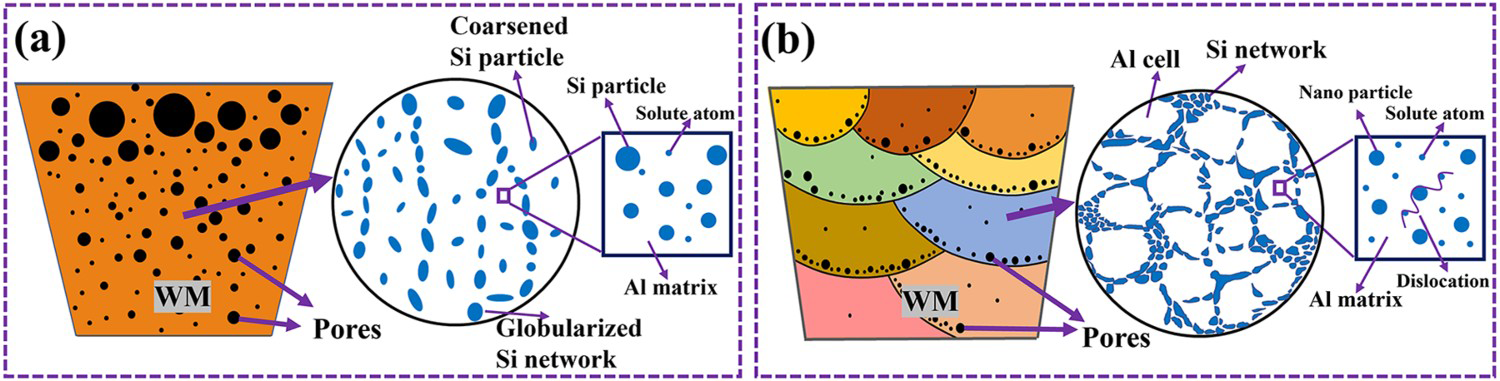
Besides the pore defects, another aspect that will affect mechanical behaviour of the welded joint is closely related to the microstructure developed in the weld seam. The possible mechanisms for the high strength of AlSi10Mg alloys fabricated by PBF-LB/M are related to the load bearing of the Si-rich networks as well as the dislocation motion related strengthening [18,26,27]. After welding, the Si-rich network morphology in the weld seam of the LMD welding is noticeably different from the single-pass welding. In the single-pass welding, the Si-rich network was largely globularised in the weld seam, whereas most of the Si-rich networks in the weld seam of the LMD joint are interconnected. Therefore, the high load bearing capacity of the Si-rich networks obtained in the weld seam is one of the main reasons contributing to the improved strength in the LMD joint. Considering the dislocation motion strengthening, the AlSi10Mg alloys fabricated by PBF-LB/M present a large volume fraction of Si-rich eutectic structure, in the form of solid solution, nanosized particles and network, all impeding dislocation motion in theory [18]. Based on our previous studies, the precipitate strengthening presents the largest contribution when the nanosized Si-rich particles within Al cells are small (∼12 nm, [18]), and the growth or suppression of fine precipitates leads to further strength loss. Interactions between nanosized precipitates and dislocations in the weld seam of the single-pass and LMD joints can be schematically shown in Figure 7. For the LMD joint, much finer Si-rich precipitates inside α-Al cells are observed in the weld seam. However, only a few tiny precipitates are present, which is likely due to the solutionising effect of the relatively high heat input reached during single-pass welding. Furthermore, the importance of the small α-Al cell size in the weld seam produced by LMD welding is reflected on the Si-rich eutectic network boundary contribution to strength through dislocation motion hindering. Based on the above result, it can be concluded that the enhanced UTS is mainly attributed to the reduced porosity and the sound microstructures in the weld seam of the LMD joints.
Conclusions
Based on the present results, the following conclusions can be reached.
The maximum size and the porosity of the hydrogen pores of the weld seam in the welded joint for AlSi10Mg alloys fabricated by powder bed fusion-laser beam/metal are 171.3 μm, and 1.7%, respectively, which are significantly reduced by using laser metal deposition welding. The ultimate tensile strength of the welded joint produced by laser metal deposition reaches 318.8 MPa, and the microhardness of the weld seam is in the range of 99.5∼105.4 HV. Compared with single-pass welding, the microhardness and the ultimate tensile strength are increased by 27.6% and 60.6%, respectively. Significant refinement of α-Al cells and Si-rich eutectic phases and increased connectivity of the Si-rich cellular networks are obtained in the weld seam of the welded joint produced by laser metal deposition. The solid solution strengthening coming from the Si element in the Al matrix within the laser metal deposition weld seam is better than that of the single-pass welding. The laser metal deposition welding has a kernel average misorientation value of 1.16° in the weld seam, which is lower than that of single-pass welding (1.98°). This indicates that a reduced local strain concentration in the weld seam has been obtained by using laser metal deposition welding. The volume fraction of high angle grain boundaries in the weld seam is 68.5% for laser metal deposition welding, which is significantly increased compared to single-pass welding (45.9%).
Footnotes
Disclosure statement
No potential conflict of interest was reported by the author(s).