






Abstract
To reduce the lead time and costs for developing short run production injection moulding tools the potential of additive manufactured mould inserts is investigated. These hybrid moulds are compared to conventional steel-based moulds, considering mechanical and thermal differences. For part production and insert material, respectively polypropylene and polyamide12 manufactured by Multi Jet Fusion (MJF) are chosen. Moldex3D simulation results show that lower clamping forces and injection pressures are sufficient upon using MJF inserts due to a 20 times lower thermal diffusivity compared to conventional steel, resulting in thinner skin layers and increased solidification times. Practical injection moulding parameters have been optimized by reducing the cooling time with 75 seconds (60%) using forced convectional cooling at 15 °C. Core and cavity inserts show a deviating cooling behaviour linked to the higher amount of insert material and presence of steel. The wear of the mould inserts is minor after producing 360 parts..
Introduction
Injection moulding is one of the most widely used methods in polymer processing and accounts for more than 70% of component production [1, 2]. This process is typically used for mass production of already optimised parts [3, 4]. However, new trends on the product market show a growing popularity of smaller production cycles of personalised and specific parts, as well as prototypes for which conventional injection moulding is expensive and time-inefficient [5]. This explains the increasing interest in integrating additive manufacturing (AM) production methodologies in which layer by layer is produced. However, AM has some constraints since not all materials can be used and the intrinsic product properties can be different [6, 7]. Therefore, hybrid moulding has been introduced [8-10], in which the mould inserts – containing cavity and core to form the part – are produced with an alternative manufacturing technique and placed in a conventional steel-based mould frame. If a mould housing is already available, the lead time before production can be reduced from several weeks to several days or even hours [5]. The use of rapid tooling techniques, such as laser machining of ceramics, carbides and hardened steel has already proved valuable in fast mould making [11], though they are expensive for the use in short-run production series.
Integration of AM mould inserts offers, besides fast production, the benefits of cost reduction and freedom to design complex internal shapes enabling the integration of conformal cooling channels, as already covered with selective laser sintering (SLS) [12]. Upon using stereolithography (SLA) inserts, brittle fracture behaviour, for which the yield stress can be used as a failure criterion, is encountered [13]. Combining steel and SLA for core and cavity inserts to form one part causes unfortunately fatal warpage of the moulded product, which can be ascribed to the too great deviations in thermal conductivity of both materials [14, 15]. Owing to the different thermal behaviour of AM materials, significant prolongation of the injection moulding cycle occurs as well [16], since cooling represents the largest part of the total cycle time [17]. Notably, Stratasys defined PolyJet Digital acrylonitrile butadiene styrene (ABS) polymer mould inserts that are economically interesting in case an amount of 5–100 parts is necessary [18]. Failure of Digital ABS mould inserts is mainly initiated by the effect of a higher overall shear rate due to the claimed absence of a skin layer near the cavity walls [19]. Another method which demonstrated the usefulness of AM is casting tools which subsequently can be used to produce moulds [20].
Further research is still necessary to expand the amount of possible insert materials and to gain deeper knowledge about the effect of insert materials on the process and final products. The present research focuses on polyamide12 (PA12) inserts manufactured by multi jet fusion (MJF) printing technology of which the principle is given at the top of Figure 1. The first crucial differences between conventional and AM inserts are reported in the present work by means of both simulations and experimental analysis, which is currently only done to a limited extent in the polymer processing field.
Overall methods, goals and analysis steps. For MJF equipment: thin layer of powder (1); build platform (2); (IR)-heating lamps (3); ink (4); fusing agent; infrared light (5): sintering detailing agent (6).
Materials and methods
Materials
The mould insert material is HP MJF PA12, with a theoretical comparison also for P20 Steel. For the injection moulding, Motip Heat Resistant Lacquer is utilised as mould coating and polypropylene (SABIC® PP575P) as homopolymer.
Overall methods and goals
Figure 1 represents the performed research and analysis steps. MJF of PA12 was first conducted to produce test specimens and mould inserts. Data have been recorded regarding tensile strength, density and thermal conductivity. Afterwards, polypropylene (PP) parts were manufactured in the PA12 inserts to optimise processing parameters.
Multi jet fusion
All test samples are produced by MJF on an HP MJF 4210 machine which is schematically represented in Figure 1 (top). In MJF, a thin layer of powder (1) is being spread over the build platform (2) and heated to a near-sintering temperature by infrared (IR)-heating lamps (3). An ink (4) is sprayed over the powder in the desired shape of the layer to bind the powder particles together. This ink functions as a fusing agent and promotes the absorption of infrared light (5) to which the material is later exposed [21]. At the same time, a detailing agent (6) which inhibits sintering is deposited near the edges of the parts. After exposure to the IR-light, the ink sprayed powder will fuse into one another and solidifies. In this way, the parts are created layer by layer.
AM part characterisation
The Young's modulus and stress at yield were evaluated by a tensile test on an Instron5565 machine according to ISO 527, performed on ISO 527 1A samples. The bluehill 2 software was used to determine the modulus as the directional coefficient between 0.05 and 0.25% strain and the stress at yield by the 0.2% offset method. Density was determined according to ISO/DIS 1183–1 method A; immersion in ethanol, using a Precisa XR 205SM-DR. Thermal conductivity and heat capacity were measured according to ISO 22007–2 on a Hot Disk TPS 2500S device [22]. A Kapton sensor ‘Hot Disk 5465’ with a radius of 3189 mm and a resistance of 6779 629 Ω was used on round test disks with a diameter of 50 mm and an average thickness of 5 mm.
Injection moulding
Before injection moulding, the inserts were coated with black coloured Motip Heat Resistant Lacquer. Six layers were sprayed on the mould surfaces of the PA12 inserts and cured at 80°C during 1 h in a ventilated lab oven. Injection moulding of the specimen was performed with an Engel 28 T E-Victory. A schematic representation of how the inserts were placed inside of the mould housing is represented in Figure 1 (bottom right). The set-up can be divided into three main parts: injection unit, mould (housing + insert) and the ejection/clamping unit. The main difference between conventional injection moulding and hybrid moulding can be found in the middle part. Here, the mould housing (1), separate aluminium cooling plates (2) and additive manufactured inserts (3) are located. During the injection moulding tests, cooling water with a temperature of 10°C was sent through the cooling plates. To manufacture the parts, the entire cavity was located in the AM-insert on the ejection side. The insert on the injection side only contained a spacing to let the sprue (4) reach the cavity and a flat surface which formed the upper plane of the spinning top. The produced specimen had the shape of a small 1.5 mm thick hexagonal plate with small protrusions where the ejector pins were located, as specified by the cavity insert in Figure 2 (left and middle).
Left; specification of the cavity mould insert; Middle: an actual associated injection moulded product; Right: set-up to apply forced convection cooling on the mould inserts using cooled pressurised air.
The middle ejector pin was not solely important to eject the moulded part, but as well to absorb the largest amount of impact energy created by injecting the polymer melt into the cavity. Since the sprue is ejected as well with the part, the whole product forms a spinning top. A Testo 875 thermal infrared camera was used to measure the surface temperature of the moulded parts and inserts. For each set of parameters, at least five IR pictures were taken. The average of the highest surface temperatures present in the pictures was used for comparison purposes. To monitor the wear of the ejector pin shafts, microscopic images were collected with a Keyence VHX-500FE Digital microscope.
An in house shaped and developed nozzle illustrated in Figure 2 (right) was used in certain experiments to achieve ultimate airflow at 15°C on the surface of the mould insert thus to provide for cooling by forced convection.
Results and discussion
Quantification of thermal diffusivity difference

Material properties of MJF PA12 and P20 specimen as used for the simulations.

Measured in the present work.
Retrieved from Moldex3D database.
Evaluation of impact different thermal diffusivity for conventional vs. hybrid moulds on simulated flow and cooling characteristics
Initial (testing) injection moulding simulation parameters (run 1 & 2).
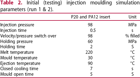
Comparing injection moulding in a P20 steel (left) and MJF PA12 (right) insert, it follows from Figure 3 that the latter case results in a lower required clamping force and polymer melt pressure during filling. An injection pressure of 13 MPa proves to be sufficient for the application in both P20 steel and PA12 inserts, which lies within the expected range [16], but with PA12 the value is ca. 0.6 MPa lower. The cause can be related to the amount of skin layer in the injection moulded part being lower. Presence of a skin layer obstructs the melt flow since it reduces the cross-section of the cavity, resulting in a higher required pressure to ensure complete filling. The amount of skin layer can be assessed using the polymer temperature at the end of filling which is represented in Figure 4. It follows from this figure that the layer of strongly cooled polymer on the mould surface is significantly larger for the specimen produced in the P20 steel insert, making the theory about the lower needed forces in the MJF PA12 insert plausible. Owing to the higher thermal diffusivity of P20 steel, the heat of the polymer melt in contact with the steel will be conducted much faster than in PA12. This will locally reduce the time to reach the crystallisation temperature, resulting in a thicker (solid) skin layer, 23, 24].
Clamping force variation (line) and filling pressure (gradient) at the end of filling in P20 steel inserts (left) and PA12 inserts (right). Simulation conditions as represented in Table 2; no forced convection. Comparison of final simulated temperature of a part produced in a P20 steel and MJF PA12 mould insert. The used simulation conditions are represented in Table 2; no forced convection.

A next logical step is thus to adapt the (closed) cooling times. The time to reach the ejection temperature is defined by Moldex3D as the required closed cooling time starting from the end of packing until a pre-set ejection temperature is reached. The generated values are 4.5 s for the P20 insert and 17.8 s for the PA12 insert. This affirms that a lower thermal diffusivity of the insert material results in a deteriorated cooling behaviour. It is thus not surprising that the temperatures of the mould inserts at the end of closed cooling show a very different behaviour, as can be noticed in Figure 5. With a closed cooling time of 7 s, for the PA12 case, a much more heterogeneous temperature profile is obtained, whereas for the P20 steel case, the limit of homogeneity already starts to be reached. For 18 s (extra run), this heterogeneity even remains highlighting the need for longer (closed) cooling times again.
Temperatures of the mould inserts at the end of closed cooling using the simulation conditions represented in Table 2; no forced convection.; for PA12 insert also the result after 18 s closed cooling is shown, still displaying heterogeneity.
Interesting to note is that for the PA12 case, the core insert has a slightly higher surface temperature (53°C) than the cavity insert (51°C) at the end of closed cooling for 18 s. This could be assigned to an overall higher volume of 8.4% insert material on the core side which has the capacity to retain more heat. Also, the presence of steel ejector pins in the cavity insert, being able to locally conduct the heat faster reduces the overall surface temperature of the insert. In Figure 5, locally cooler spots can indeed be seen around the ejector pins for the PA12 inserts after 7 and 18 s of closed cooling.
From simulation to injection moulding experiment: optimising closed and open cooling and quantification of wear
Starting values for injection moulding experimental parameters.

The simulations showed a slightly higher surface temperature of the core insert compared to the cavity insert at the end of closed cooling (Figure 5; 18 s). It has thus been investigated if a similar behaviour occurs during practical injection moulding with 25 s closed cooling time and extra open cooling time. Surface temperatures of core and cavity have been measured at different time steps of open cooling during a continuous cycle using IR images. Figure 6 displays the maximal associated surface temperatures during a total open cooling time of 100 s (thus total cooling time of 125 s). Five seconds after mould opening, the surface temperatures of the inserts are statistically equal, although the order of the simulations is still respected. This either implies that the extra 7 s in closed cooling make a difference or temperature dependent physicochemical properties are relevant. In the simulations in the previous subsection, a constant value of the thermal conductivity measured at ambient temperature is for instance considered. Since the insert will heat up to temperatures above 50 or 60°C, the deviation might become thermally relevant.
Experimental values of the insert surface temperature as function of open cooling time in a continuous cycle. With a closed time of 25 s and open time of 100 s; no forced convection; target cooling is below 30°C (horizontal line).
From Figure 6 (25 s closed cooling), an open cooling time of 60 s can be chosen as starting value for the additional tests with forced convection cooling since the core inserts surface temperature is 30°C after this amount of time (horizontal line). During injection moulding, significant attention has been paid to shortening the total cycle time per part. Since the cooling times are responsible for the largest share of the total cycle time [2–25], the open and closed cooling times are gradually decreased while keeping a stable cycle and producing good parts. For example, a closed cooling time of 10 s is sufficient to eject non-deformed parts at a slightly higher temperature of 100°C. Owing to this first design step, 15 s is subtracted from the total cycle time (25–15 s closed cooling time; 60 s of open cooling time; total cooling time 75 s).
To aid faster open cooling of the mould inserts, forced convection was additionally applied by blowing cooled pressurised air of ca. 15°C on the insert surface. Multiple stable cycles of at least 30 parts have been produced with a closed cooling time of 10 s, as determined from the first design step, and different open cooling times. Figure 7(a) displays the interesting phenomenon of the inserts maintaining a higher surface temperature for continuous cycles with shorter open cooling times. This indicates a heat build-up in the inserts. However, with 30 s open cooling time, surface temperatures are below 30°C, which is the desired maximal surface temperature before starting a new cycle [16]. Thus, based on short-run production, an open cooling time of 30 s follows as a second design criterion, which implies a further 40% reduction in total cooling time (75–40 s).
(a) Comparison of experimental core insert surface temperature in continuous cycles with different open cooling times (closed cooling time of 10 s;). (b) Surface temperatures during open cooling comparing forced convectional cooling with ambient air cooling; target cooling is below 30°C (horizontal line).
To implement a safety margin, an open cooling time of 40 s with forced convection cooling (10 s closed cooling) is although recommended to perform a long production run. Such run is explored in Figure 8(b). Here after every 10 parts of a total of 260 parts, the maximal surface temperature was measured. These surface temperatures are higher than during the short-run with forced convection cooling (30 parts), as also included in the same figure. This is presumably caused by heat accumulating more and more inside the mould inserts during the increasing number of cycles. Nevertheless, compressed air cooling accelerates the decreasing of the surface temperature and 260 parts with stable dimensional properties have been successfully produced in one day without causing fatal damage to the insert. It can be concluded that for safety measures the open cooling time must always be chosen with a safety margin to prevent early failure of the insert material due to heat build-up.
Wear analysis of the coated MJF PA12 mould insert after producing 360 parts according to the optimised processing procedure.
The most prominent visible wear relates to the removal of some coating directly after the first few parts in the coated insert. On the core side, an imprint of the part could be seen after only 5–20 produced parts, as represented by (1) in Figure 8. To investigate whether the visible damage affects only the coating or also the insert, the coating was removed using di-isopropyl ether as a solvent. The uncoated surface showed no signs of visible damage without the aid of microscopic imaging. Still, the inserts could be used to produce 360 parts successfully and even 100 parts extra in the same inserts at a later time. In the cavity side, cracks have been detected in the coating, mainly located around the holes for the ejector pins (2) in Figure 8. This can likely be assigned to the thermal expansion of the inserts and ejector pins after producing parts which will create more friction during ejection, also bearing in mind the thinner skin layer. This causes extra stress and will possibly damage the insert and top layer of the coating.
The dimensions of the ejector shafts as represented in Figure 9 were monitored to investigate whether the friction causes dimensional changes. A direct increase of the ejector shaft diameter can be noted indicating friction-related wear. Cracks can also be seen in the core insert around the sprue hole (3) in Figure 8. Since the hot melt will flow through the sprue, thermal expansion of this part is expected which might cause stresses leading to damage of the coating and insert. Since the sprue is an anchored part, friction-related wear does not occur. This means that mainly the coating experiences failure. Interestingly, the coating can be removed using the correct solvents and afterwards the insert can be recoated and used again. Hence, the hybrid mould approach study has potential in an industrial framework.
Variation of the (average) diameter of the ejector shafts with more parts produced. Study of the relevance of wear.
Conclusions
The use of MJF PA12 technology to produce injection moulding inserts is demonstrated as promising for subsequent injection moulding. Upon optimising open and closed cooling times by combining simulations and characterisation of injection moulded products over 360 parts could be produced using the same inserts after which they were not yet fatally damaged.
Thermal differences cause the greatest deviations with conventional injection moulding, with a ca. 20 times smaller thermal diffusivity of the polymeric inserts leading to a smaller skin layer, lower required pressures and forces, and prolonged cooling times. The core insert cools down slower linked to the lesser presence of highly thermal conductive steel and more volumetric capacity to hold up heat. Applying cooled pressurised air during open cooling reduces the total cycle time for one part over 50%.
In future work, the relation between processing conditions and final product properties will be studied more in depth, including also detailed impact and wear data. The simulation framework will also further tuned in view of more detailed input (temperature- and composition-dependent) parameters.
Footnotes
Acknowledgements
The authors would like to thank ZiggZagg for kindly providing the AM samples. Stef Boden is gratefully thanked for the practical support and processing data.
Disclosure statement
No potential conflict of interest was reported by the author(s).