
Abstract
Composites of polyaniline and polyvinyl alcohol were prepared through an in-situ polymerisation of aniline using ethanol as a coagulating agent and characterised for their applicability as supercapacitor electrode material. The thermally stable composites afford moderately high electrical conductivity. Composite with 0.03 mol aniline exhibited a high electrical conductivity of 0.371 × 10⁻² S/cm. The variation in electrical conductivity with an increase in aniline content is consistent with the band gap energies estimated from electronic spectra and IR drop. SEM analysis confirms coral-like nanowires of polyaniline (PANI) grown within the polyvinyl alcohol matrix. Cyclic voltametric studies revealed that the composites are highly electroactive as they allow easy diffusion of ions through the nanowires of PANI for efficient electrochemical reaction. The composite with 0.03 mol aniline has a superior specific capacitance of 302 Fg−1 at a scan rate of 5 mV/s. The composite exhibited a maximum energy density of 41.94 Whkg−1 and excellent stability even after storage of 18 months in ambient condition with 83.3% capacitance retention.
Introduction
The rapid advancement in technology concentrated everything into one's fingertip with the development of small and lightweight electronic gadgets. One of the key factors aiding this progress in technology is through developing energy storage devices like supercapacitors [1, 2] fuel cells [3] and rechargeable batteries [4, 5]. In order to keep up with the rapid evolution of technology, researchers are desperately searching for new lightweight, flexible and efficient materials which can serve as active electrodes in energy storage devices. Conducting polymers (CPs) are organic polymers having extended
 electron conjugation along the polymer backbone and having electrical conductivity similar to that of metals and semiconductors [6, 7]. They attracted considerable attention due to their tuneable electrical conductivity, electrochemical characteristics, environmental stability, ease of synthesis and tuneable morphology [8-10]. The inherent properties led CPs to find their application in microelectronics [11], electronic packaging [12], fuel cells [3], supercapacitors [2, 13] rechargeable batteries [4], photonics [14], electro catalysts [15], corrosion protection [16], artificial muscles [17, 18], sensor [19-21], etc. Even though CPs are considered to be promising electrode material individually, they suffer from low solubility, poor processability and low cyclic stability towards repeated oxidation and reduction cycle [22]. There have been extensive studies to counter the drawbacks associated with CPs and some of them, focussing on the synthesis of composites with metal oxides [3], carbon materials [1, 23], metal nano-particles [4,14, 24], co-polymerisation [25-27], using surfactants [28] and blending CPs with hydrogels and other polymer matrices [29].
Polyaniline (PANI) has shown promising advantages over other CPs due to its high environmental stability, interesting redox chemistry, cheap monomer cost, light weight, fast response time, higher surface area and stability in aqueous media which make it an excellent candidate for electrode material fabrication [30, 31]. Nonetheless, PANI suffers from poor processability, brittle nature, in-fusibility and inferior mechanical property limiting its applicability, especially in device fabrications [32]. To improve the mechanical properties of PANI, it has been hybridised with different materials like other polymers and hydrogel systems [33, 34]. In order to exploit the full potential of PANI as a high-performance electrode material, a highly porous nanostructure with excellent mechanical and thermal properties is required [35]. Porous nanostructures can provide a larger surface area and easy diffusion of electrolytes essential for an efficient electrode reaction [36-38]. Recent studies have shown that PANI can be coated on to different micro-fibre or nano fibre substrate to produce nano porous structures that can allow short diffusion path for the electrolyte to diffuse into the active material efficiently [39]. A hydrogel, being highly porous and capable of imbibing large amounts of water allows electrolyte to diffuse more easily into the bulk to interact with active material efficiently inside the hydrogel network [40, 41]. Polyaniline/polyvinyl alcohol (PANI/PVA) hydrogel system has an advantage over other polymers systems due to the combination of inherent properties of both hydrogel and the CPs [6]. PVA affords mechanical strength, film-forming property, good chemical stability and has the capability of accumulating a large amount of electrolyte within the solid phase [34, 42-44]. In the present work, we synthesised PANI/PVA composites via in situ chemical polymerisation of aniline and demonstrated its applicability as an active electrode material for supercapacitors. The primary objective was to synthesis a hydrogel/conducting polymer hybrid material functioning as supercapacitor as they are highly promising for fabrication of bio electrodes from the viewpoint of developing bio-artificial muscles. Obtaining a moderately high capacitance and cycle stability are the requisites of attaining high-performance bio electrodes for future biomedical devices.
Experimental study
Materials
Polyvinyl alcohol (fully hydrolysed mol.wt. 60,000–1,25,000) was purchased from HiMedia Laboratories India. Aniline (AR, 99.5%) was purchased from Spectrochem India and was distilled under vacuum and stored at −10°C before use. Potassium peroxodisulphate (K2S2O8, KPS AR Grade ≥99%), Hydrochloride (HCl, 35%), ethanol (>99%) were purchased from Merck specialities, India. Deionised water and ethanol were used as solvents for all the synthesis.
Preparation of polyaniline/polyvinyl alcohol composites
PANI/PVA composites with different composition of aniline were synthesised by in situ polymerisation method using KPS as an oxidising agent. A 1% PVA solution was prepared in 1 M HCl by gentle heating. The resulting solution was cooled and maintained at a temperature of 4°C and an appropriate amount of aniline was added. To this solution 100 mL of KPS solution in 1 M HCl was added dropwise with constant stirring and kept for 4 h. After the completion of reaction, the reaction mixture was kept at 0°C for a further 20 h. Ethanol is added to the resultant solution to coagulate the product. The greenish-black lump obtained was washed using distilled water to remove excess ions and other impurities and the lump was dried at room temperature 35°C for 3 days to obtain the PANI/PVA composites. The composites prepared for varying compositions, 0.01, 0.02 and 0.03 moles of aniline were respectively labelled as PP01, PP02 and PP03 (Figure 1).
Schematic representation of the preparation of PANI/PVA composites.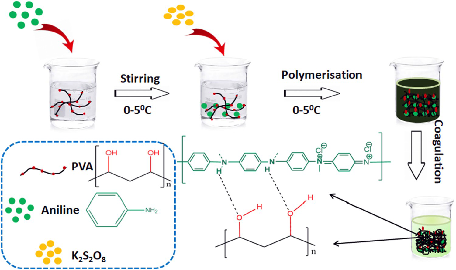
Apparatus
JASCO FTIR-4100 spectrometer was used to record the IR spectra of the materials studied. UV–Visible spectra were recorded using a JASCO V-750 spectrophotometer (Spectral band width 2 nm, scanning speed 1000 nm/min) in the spectral range of 200–900 nm using dimethyl sulfoxide as the solvent and the bandgap energy was then calculated from the UV spectral data. The surface morphology and particle size were analysed with Gemini SEM 300 instruments at 25 KV. Thermal stability was determined by thermogravimetric analysis (TGA) using a TA Q50 instrument by heating the sample from 30°C to 650°C at a heating rate of 10°C per minutes under a nitrogen atmosphere. The conductivity studies of composites were carried out using an alpha high-performance frequency analyser (NoVo technologies) with a wide frequency range of 10−2–107. The samples were sandwiched between two gold-plated copper electrodes of the spectrometer and the measurements were carried out at room temperature and ambient pressure. The electrochemical properties of PANI/PVA composites were studied by using Zahner Zennium pro electrochemical workstation. Three standard electrodes were used for cyclic voltammetric (CV) measurements. Glassy carbons, platinum wire, calomel electrode (Ag/AgCl) were used as working electrode, a counter electrode and reference electrode respectively. The working electrode was prepared by mixing composite and carbon paste in the ratio 80:20 to form a homogenous slurry by using isopropyl alcohol as a solvent. Then the slurry corresponding to the mass of 3 mg was coated on electrode and transferred into an oven for drying at 50°C overnight. 1 M HCl was used as an electrolyte. The specific capacitance of the sample was calculated using Equation (1) [45].
 is the integral area of the CV curve.
Energy density (E, WhKg−1) was calculated using Equation (2)

 represents voltage range.
Results and discussion
FTIR spectra
The FTIR spectra of PANI/PVA composites for varying concentrations of aniline and the FTIR spectra of pure PVA, PANI as shown in Figure 2. Pure PANI shows characteristic peaks at 1637 and 1483 cm−1 are attributed to C–C stretching of the quinoid and benzenoid ring, respectively, and the peaks at 1123, 2920 cm−1 are assigned to the C–C and C–H stretching vibrations, respectively [44]. The number of quinoid units is not equal to number of benzenoid units in PANI since there is an apparent difference in the relative intensity of quinoid to the benzenoid band which is a measure of the degree of the oxidation of the polymer chain. The band at 1299 cm−1 was attributed to the C–N stretching of the benzenoid ring. The peak observed at 1123 cm−1 is associated with the vibrational mode of N = Q=N (Q refers to the quinonoid type rings). The FTIR spectra of PVA show a strong absorption peak at 3420 cm−1, which was attributed to the O–H stretching vibration due to H-bonding. The C–H stretching and bending vibrations are observed at 2924 and 1417 cm−1. The small peak at 1324 cm−1 is due to the –CH2− wagging and intense peak at 1097 cm−1 is due to the C–O stretching vibrations and the C–O stretching at 1093 cm−1. All three composites show similar absorption bands characteristics of PANI and PVA. It can also be seen that H-bonding is predominant in all three composites. Careful examination of the characteristic peaks of the composite reveals that there is a shift in the position of the bands from 1637 to 1627 cm−1, 1483 to 1423 cm−1 for quinoid and benzenoid rings. Also C–C stretching value decreased from 1123 to 1114 cm−1 as the PANI content in the composite increases, and this may be because of an increase in the electron density in polymer backbone as a result of the formation of composites with PVA [34].
FTIR spectra of PANI/PVA composites PP01, PP02, PP03 and pure PANI and PVA.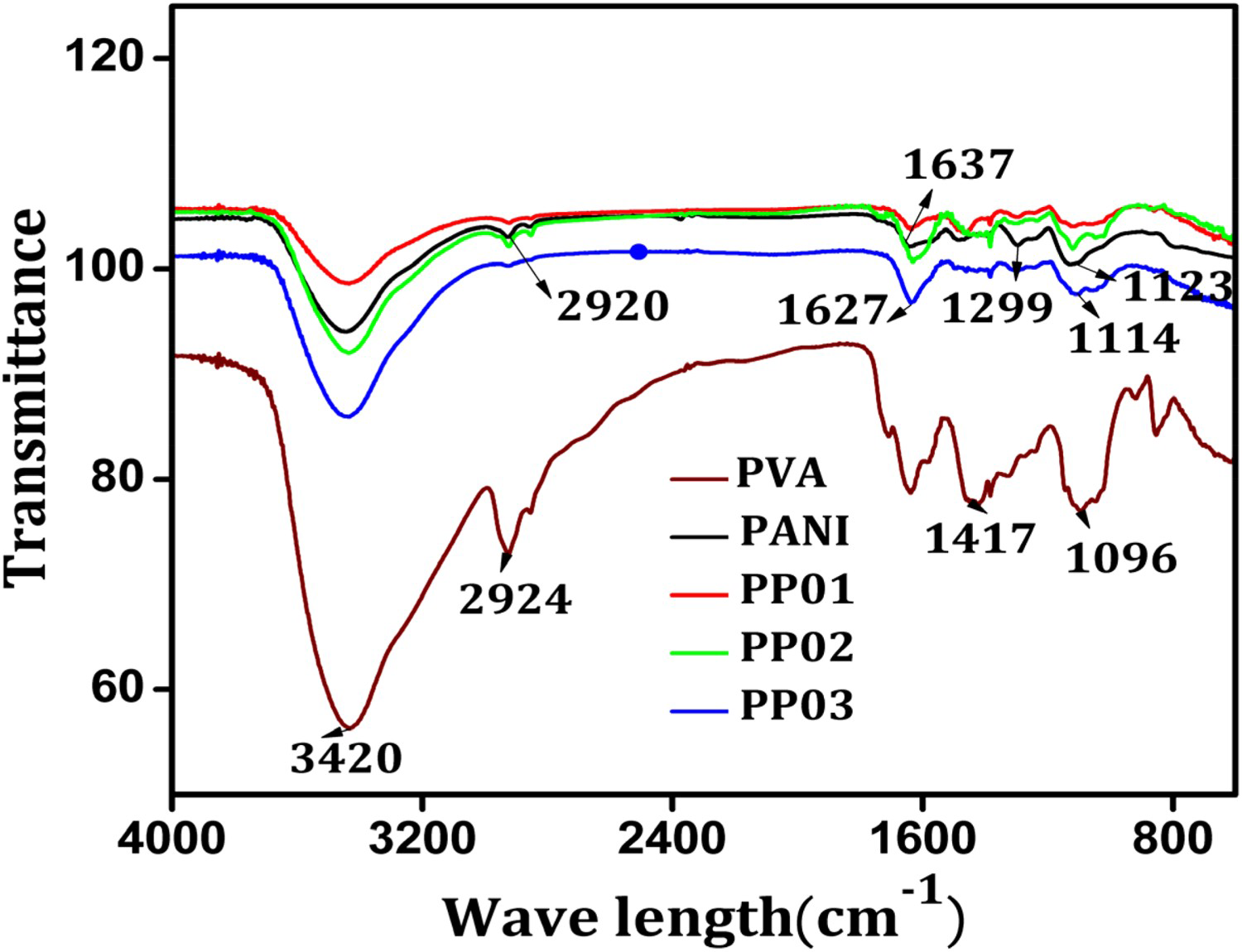
UV–VIS spectra
The UV–VIS spectra of pure PVA and PANI/PVA composites are shown in Figure 3(a,b). PVA does not absorb in the visible region but exhibits a sharp peak at 260 nm. Composites PP01, PP02 and PP03 have two characteristic peaks at 330 and 630 nm due to the presence of PANI in the composites which are, respectively, attributed to π to π* transition of the quinoid ring and the n to π* transition of the benzenoid ring, together with an extended tail representing the conductive form of PANI [46-48]. The absorption peaks around 330 nm correspond to the excitation of amine nitrogen of the benzenoid segments. In all the composites, the peak around 440 nm is ascribed to the polaron/bipolaron transitions. The characteristic peak around 630 nm corresponding to the n to π* transitions of the benzenoid ring was found broadened due to the H-bonding interactions of PVA in the composites. A slight increase in the ultraviolet absorption position in the composites will present a redshift gradually with the increase in PANI content. The band gap of the pure PANI and PANI/PVA composites were calculated from UV–VIS spectra and the results are presented in Table 1. The band gap energy was calculated using Equation (3)
(a) UV–Visible absorption spectra of PVA, (b) UV–Visible spectra of PANI/PVA Composites PP01, PP02 and PP03 in DMSO. Composition, DC electrical conductivity values and band gap energies of PANI and PANI/PVA composites.
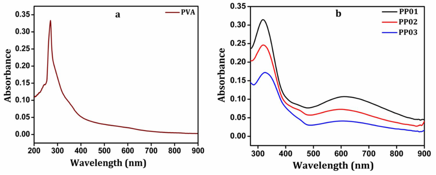
The band gap of pure PANI is 1.95 eV and for PANI/PVA composites PP01, PP02 and PP03 are 3.21, 3.14 and 2.96 eV, respectively. This shows that as the PANI content in the composite increases, the band gap decreases due to the increase in electron density in the polymer backbone as PANI content increases. The intensity of absorption bands of composites increases with increasing the aniline content. Estimated band gap energy values are in the semiconducting range and are consistent with the electrical conductivity of the samples [34].
Scanning electron microscopy
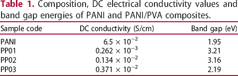
SEM images of the samples studied are shown in Figure 4. The SEM image of PVA is quite homogenous, as shown in Figure 4(a). Figure 4(b) shows the SEM image of pure PANI revealing a coral-like nanowire morphology for the PANI formed. Morphological investigations also provide us with the influence of the concentration of aniline in the composites studied [49]. The incorporation of PANI into the composites develops cracks or unevenness. As the amount of aniline composition increases, the coral-like PANI particles aggregate to form clusters of flakes. The incorporation of PANI into the matrix develops heterogeneity in the matrix, as clear from Figure 4(c–e). The formation of PANI clusters within the polymer matrix could be attributed to the hydrophobic nature of PANI molecules, which may aggregate due to hydrophobic dispersion force [46]. Interestingly, no separate domains for conducting and insulating components are visible, which reveals a closer association of the components and a unique chemical homogeneity of the samples. The SEM study confirmed the formation of a homogenous interpenetrating network of PANI/PVA composites.
SEM images of (a) Pure PVA (b) Pure PANI and PANI/PVA composites: (c) PP01 (d) PP02 and (e) PP03.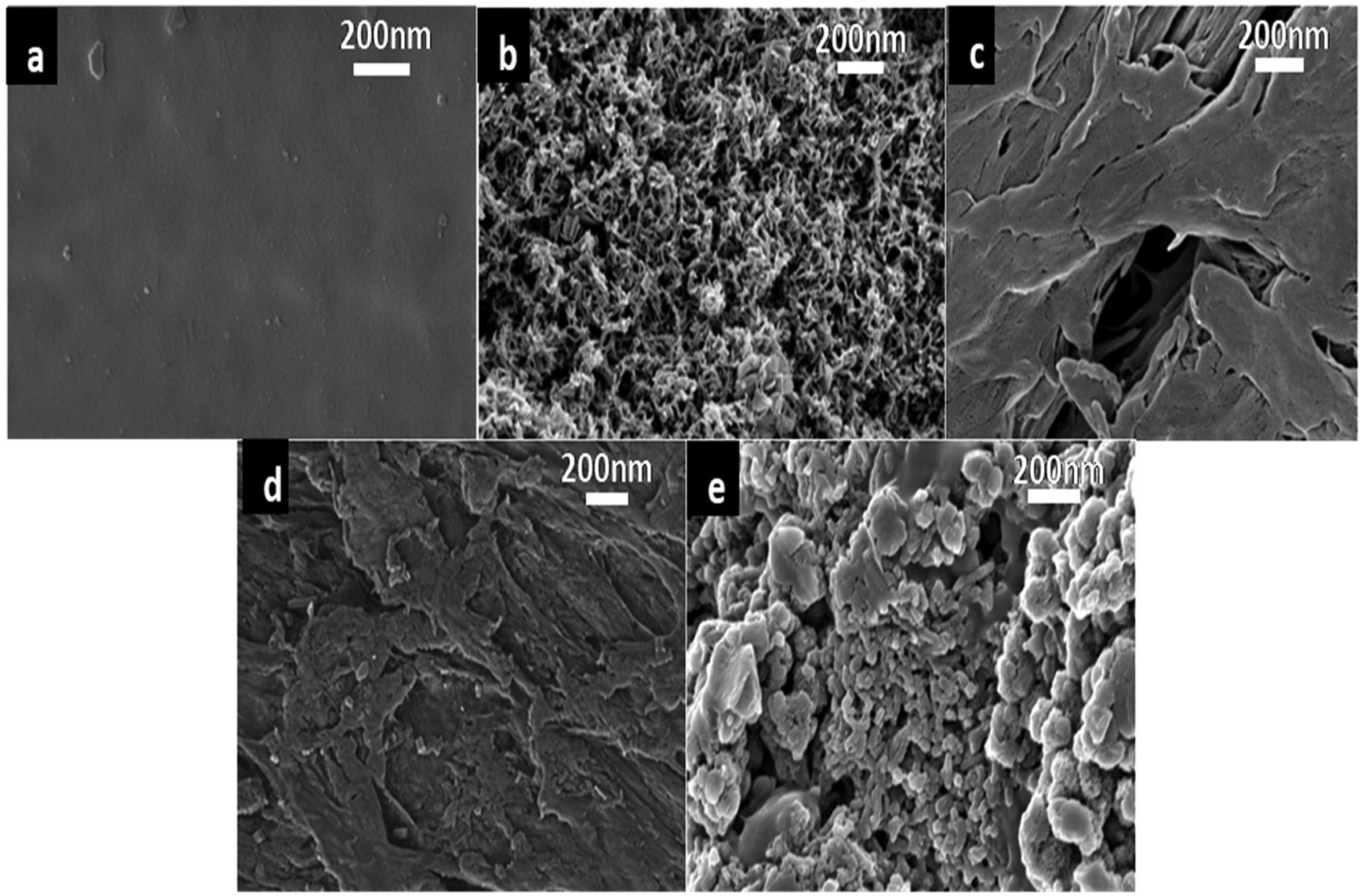
Thermogravimetric analysis
The general observation from the thermograms presented in Figure 5 is that the oxidative degradation of the polymer backbone takes place after the removal of trapped water molecules followed by dopant and low molecular weight oligomers leaving behind a very low weight % residue. The thermogram of PVA shows weight loss at three distinct regions, initially at 3% in the temp range of 30–100°C with the elimination of water and loss of adhered moisture. The weight loss of about 85% at 450°C accounts for the degradation of PVA polymer backbone. The thermogram of polyaniline showed three distinct regions of weight loss. The initial weight loss of about 13% up to 150°C is attributed to the loss of water molecules. Further weight loss of about 8% by 260°C corresponds to the removal of dopant ions. Beyond 260°C, thermo-oxidative degradation of polymer backbone takes place. The rate of decomposition is found to be maximum at the temperature of 480°C. During the degradation of polyaniline back bone, compounds such as ammonia, aniline, p-phenylenediamine, N-phenylaniline and N-phenyl 1, 4 benzenediamine are reported to be formed [26]. At around 600°C, a residual weight of 45% is left which may be attributed to the thermally stable cross-linked and polynuclear organics. The composites also show a three-step degradation mechanism, the weight loss due to the removal of water molecules which takes place up around 180°C. Then the weight loss up to 210°C is due to the removal of dopant HCl molecules. Major polymer backbone degradation occurs around 370°C. From Figure 5, it is clear that the composites showed thermal stability better than PANI [34].
Thermograms of pure PVA, PANI and PANI/PVA composites.
Electrical conductivity
The conductivity studies of the PANI/PVA composites were carried out by using the four-probe alpha high-performance frequency analyser. Pure PVA is an insulator. It is observed that the electrical conductivity of PANI/PVA composites prepared is in the semiconducting range, as shown in Table 1. The composites have conductivity less than that of PANI. The conductivity of PANI/PVA composites increases as the percentage of aniline increases in the reaction mixture. The decrease of conductivity of PANI/PVA composites compared with the pure PANI might be attributed to the presence of insulating PVA segments and the hydrogen bonding between the hydrogen of a hydroxyl group of PVA and nitrogen of aniline due to which the aniline polymerisation is inhibited [25]. The conductivity data show that composite with 0.03 mol percentage of aniline has the maximum conductivity of 0.371 × 10⁻² S/cm and the composite with 0.01mol aniline show the least conductivity of 0.262 × 10⁻³ S/cm. Thus in situ polymerisation is an effective method for producing homogeneous semi-conducting composites of higher electrical conductivities.
Swelling characteristics
Since PVA hydrogel is a component of the studied composites, in order to confirm the formation of a physical crosslinking, a swelling test was performed. The results are as shown in Figure 6. The swelling characteristics are higher for pure PVA. Compared with PVA, the swelling ratio of composites was low due to the incorporation of PANI. With the increase in PANI fraction, the number of network chains with strong physical interaction per unit volume is increased in the PVA gel. This restricts both the inclusion of water molecules into the gel and subsequent relaxation of PVA polymer chains[45]. The swelling ratio was calculated using Equation (4)
Plots of swelling ratio vs time.
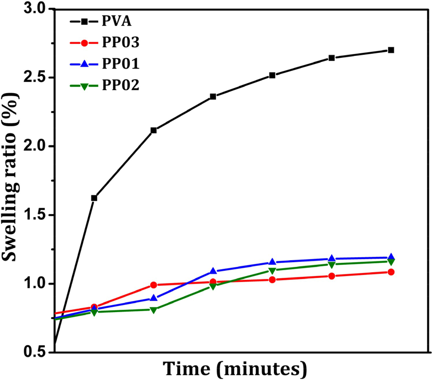
where Ws is the weight of the swollen state at a given time, and Wd is the weight in the dry state.
Electrochemical studies
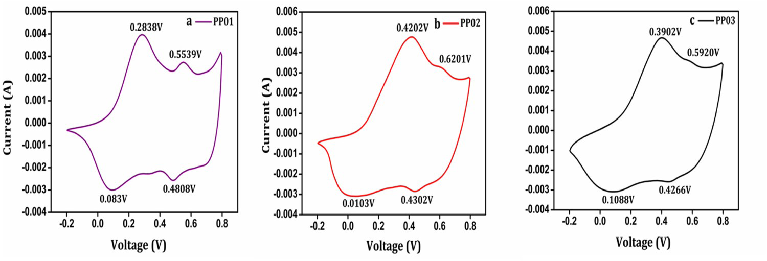
The electrochemical characteristics and redox properties were studied through CV using the prepared samples as working electrodes. The CVs of PANI/PVA composites PP01, PP02 and PP03 (Figure 7) were recorded by cycling the potential between −0.2 and 0.8V Vs SCE at a scan rate 5 mVs−1 in 1 M HCl solution. As shown in Figure 7, two characteristic peaks are observed for all the three PANI/PVA composites indicating the clear transformation between the different redox states of PANI. The general form of the electrochemical reaction taking place in the composites can be presented as:
CVs of PANI/PVA composites (a) PP01, (b) PP02 and (c) PP03.
The increase of peak currents with the increase of scan rates indicates good responsiveness and rate capability in the composites [37]. Though the electrical conductivity is not so high, the obtained high electrochemical activity of the studied composites is attributed to the easy diffusion of ions due to the porous characteristics of the conducting hydrogel composite and the nanostructured PANI present in the composites. Figure 8(a) shows cyclic voltammograms at different scan rates. The redox peak current densities increase with scan rates from 5 to 200 mVs−1. It can be seen from the Figure 8(b) that the intensity of the anodic peak increases as a function of the square root of the scan rate up to 200 mVs−1 which suggests that the process is diffusion-controlled up to 200 mVs−1 [13].
(a) CVs of PANI/PVA composite obtained at different scan rates and (b) Variation of intensity of anodic peak potential as a function of square root of scan rates.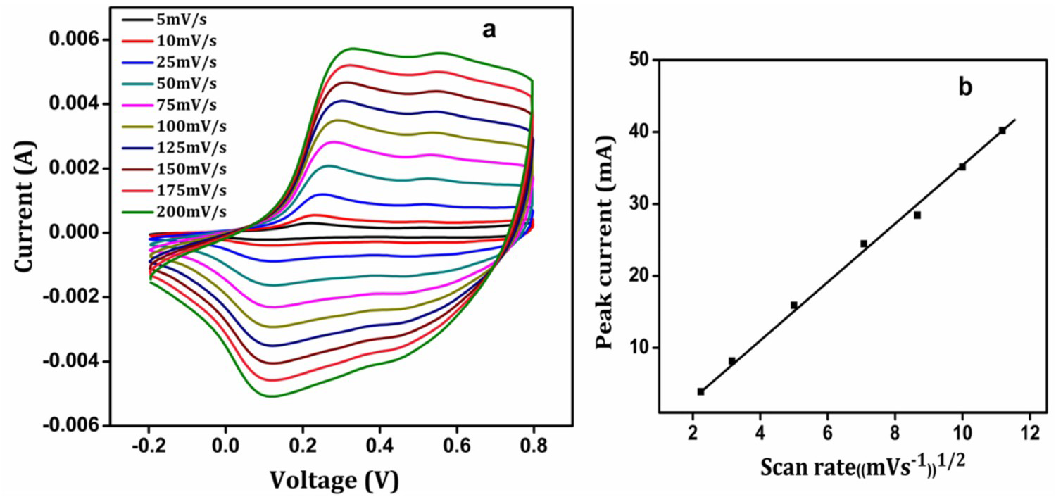
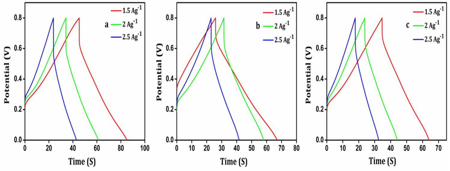
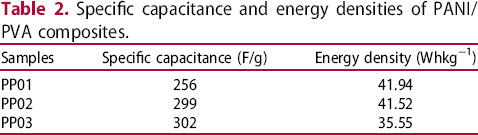
The redox peak is indicative of the presence of faradaic capacitance Ismail [33]. The specific capacitance of PANI/PVA composites PP01, PP02 and PP03 are 256, 299 and 302 F/g, respectively, at a scan rate of 5 mV/s calculated according to Equation (1) (Figure 9). The specific capacitance is found to increase with the increase of PANI content in the composites. The galvanostatic charge–discharge curves recorded at a current density of 1.5 A/g for the PANI/PVA composites are displayed in Figure 10. PP03 composite shows longer discharging time which is consistent with its higher specific capacitance value. Energy density values are calculated using Equation (3). The composites PP01, PP02 and PP03, respectively, deliver a maximum energy density of 41.94, 41.52, 35.55 Whkg−1 as shown in Table 2.
GCD curves of PANI/PVA composites PP01, PP02 and PP03 at a current density of 1.5A/g. GCD curves of PANI/PVA composites at various current densities (a) PP01 (b) PP02 and (c) PP03. Specific capacitance and energy densities of PANI/PVA composites.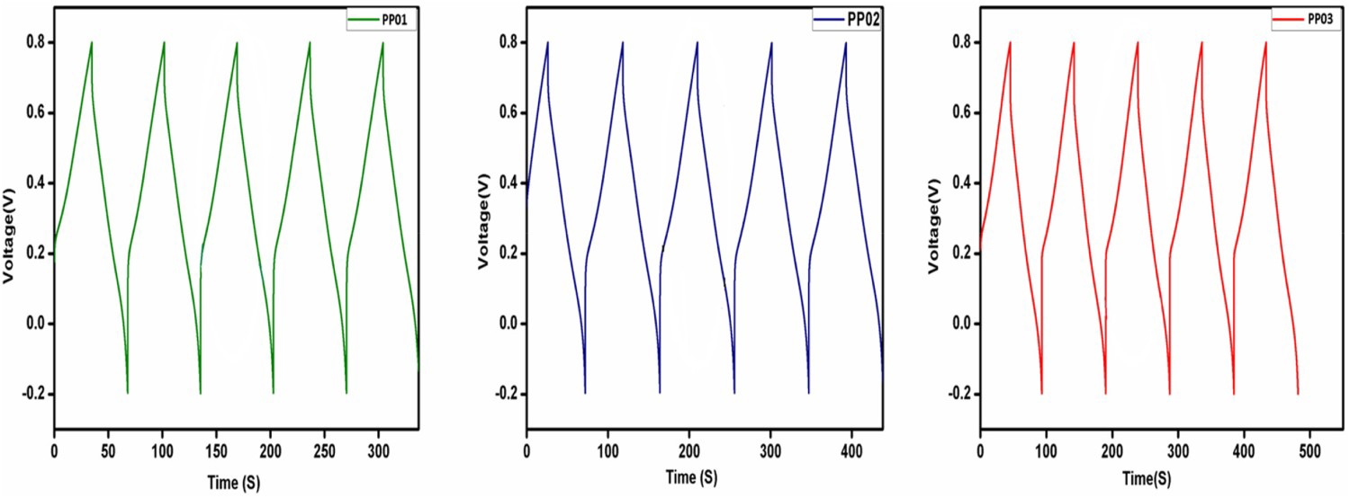
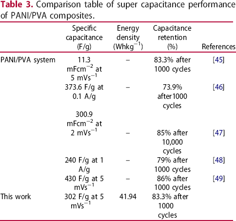
Cyclic stability is an important performance parameter for the supercapacitor electrode materials. On account of the expansion and shrinkage in cycles of charge/discharge, the faradaic capacitive performances of polymeric materials may degrade after multiple cycles leading to poor cyclic stability. Figure 11 presents the cyclic stability of PP03 composite; the capacitance retention rate is 83.3% after 1000 cycles. It is attributed to the nanoporous structure of PANI, which can efficiently overcome the expansion and shrinkage during charge/discharge cycles. A Comparison table of super capacitance performance of PANI/PVA composites reported is presented in Table 3.
Cycle stability of PP03 composite showing capacitance retention against the number of cycles. Comparison table of super capacitance performance of PANI/PVA composites.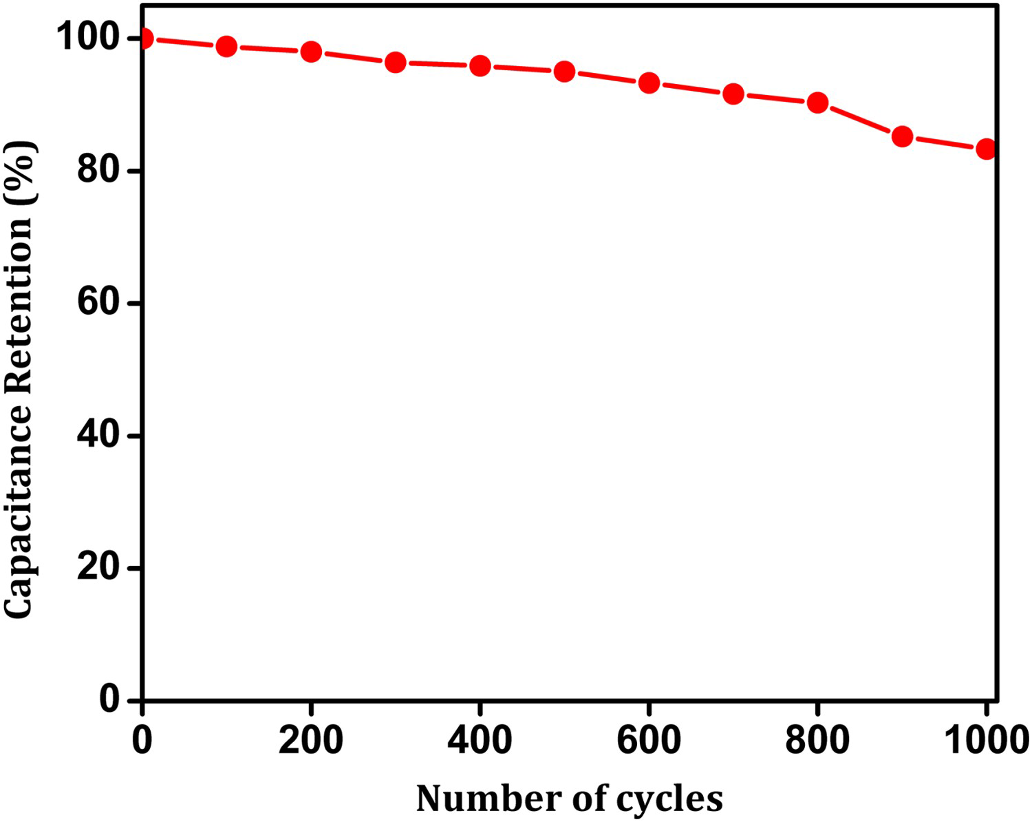
Conclusion
PANI/PVA composites with interpenetrating networks were successfully synthesised by in situ polymerisation of aniline. The swelling characteristics of the composites, its porous nature and nanostructures of PANI combined synergic effect readily increased interaction between electrode and electrolyte ions and thereby afforded high electrochemical activity and an appreciate specific capacitance values for the composites. The PP03 composite affords a high specific capacitance of 302 F/g at a scan rate of 5 mV/s and higher cyclic stability up to 83.3% capacitance retention after 1000 cycles. It also exhibited a high energy density of 41.94 Whkg−1. The SEM images and thermal studies proved the incorporation of PANI into the PVA matrix. The TGA analysis displays good thermal stability for the composites with a residual amount of 35% at 600°C compared with pure PANI. The studies revealed that the PP03 composite has electrochemical activity and thereby can be used as active electrodes in supercapacitor.
Footnotes
Acknowledgements
The authors acknowledge the CSIF, University of Calicut for providing SEM facilities, and Dr Shahin, Dept of Physics, University of Calicut for providing facilities for electrical conductivity measurements.
Disclosure statement
No potential conflict of interest was reported by the authors