
Abstract
The growth rate of pits formed on Alloy 800 in chloride solutions containing various thiosulphate concentrations was assessed by potentiostatic polarisation, in situ corrosion image observation, and image analysis. The pitting growth rate was a function of solution chemistry: in chloride solution pits were small but numerous, in chloride + thiosulphate solution, the pits were large. Competitive adsorption on Alloy 800 of chloride and thiosulphate ions affected the pitting potential and therefore the pitting growth rate on the metal. The reduction of thiosulphate to elemental sulphur accelerated the pitting growth rate in chloride + thiosulphate solutions.
Introduction
Alloy 800 is a preferred steam generator (SG) tubing alloy in pressurised-water reactors (PWR) in nuclear plants. Alloy 800 shows excellent corrosion resistance at high temperatures and high water pressures except under chemical excursion conditions. Localised regions of an alloy, such as crevices, can harbour chemical conditions that are much more aggressive than conditions in the bulk alloy [1]. Corrosion phenomena in SGs can be catalysed by thiosulphate and chloride ions that exist in crevices between the tube and the tube support during reactor overhaul and startup [2], even at low temperatures. Thiosulphate ions are produced by the reduction of sulphate by hydrazine in the PWR feedwater [3,4]. Hydrazine is added to PWR feedwater to remove residual oxygen and therefore lower the corrosion potential of SG tubing.
Pitting is commonly observed on the surface of SG tubing in solutions containing thiosulphate and chloride [5,6]. The interaction between thiosulphate and chloride ions and their effect on SG degradation are complicated, and have been shown to depend on solution pH [7,8], the ratio of thiosulphate and chloride ions [9,10], the electrode potential [9] and temperature [11]. Thiosulphate and chloride ions can synergistically damage the passive layer of an SG tubing alloy when chloride adsorption is dominant. The mechanism of pitting corrosion [12–14] involves the breakdown of the passive alloy layer with chloride and the adsorption of thiosulphate ions in the fissures. There is some debate regarding the level of chloride ion in reactor feedwater that will adsorb sufficiently on the SG alloy surface to provide sites for thiosulphate damage to the passive layer [15,16]. Newman et al. claimed that chloride accumulation on the metal surface diminished as the thiosulphate concentration in the chloride solution increased [13,17]. They claimed that pits were generated in this situation, but suggested that the electromigration and decomposition of thiosulphate within the pits tended to neutralise acid generation due to acidification in the pits, inhibiting pitting corrosion [13,17]. When the adsorption of thiosulphate is dominant, fewer chloride ions can adsorb on the metal surface to damage the passive film. Therefore, no pits are likely to initiate in this situation. If the pitting growth rate is fast, SG tubing can fail in a short time; therefore, the pitting growth rate on Alloy 800 in chloride and thiosulphate solutions in simulated crevice chemistries is investigated here.
In situ corrosion morphology observation, surface analyses and image analysis were applied to measure the pitting growth rate on Alloy 800 and to examine the effect of the thiosulphate to chloride concentration ratio on the pitting corrosion rate. A mechanism for the pitting of metal in the presence of chloride and thiosulphate ions is proposed.
Experimental procedures
Materials
Test specimens were prepared using Alloy 800 SG tubing (Sandvik, heat number 516809, outer diameter 15.88 mm, wall thickness 1.13 mm). The outer surface of the tubing was used for the tests (the inner surface and cross sections were sealed with epoxy resin). Before each measurement, the test surface was ground with wet silicon carbide papers (320, 600, 800 and 1200 grits), rinsed with water, then dried in a desiccator for 24 h. The chemical composition (wt-%) of Alloy 800 was: C(0.017), Si(0.46), Mn(0.5), P(0.012), S(0.001), Cr(21.87), Ni(32.78), Co(0.01), Ti(0.48) Cu(0.02), Al(0.29), N(0.016), Fe(43.2). The exposed area on Alloy 800 is circular with an area of ∼1 cm2.
Electrochemical measurement
The electrochemical cell used for in situ electrochemical measurement and corrosion image observation is schematically shown in Figure 1. The prepared Alloy 800 sample was placed in the electrochemical cell with the exposed surface facing the top of the cell. The electrochemical cell was filled with a solution containing NaCl and sodium thiosulphate. The pH values of the electrolyte solution in all experiments were approximately 6.89. The solutions in the cell were deaerated with high purity (99.99%) N2 for 1 h. Electrochemical measurements were conducted using a PARSTAT2273 electrochemical workstation (Princeton Applied Research, USA). Experiments were conducted with a three-electrode cell: Alloy 800 was the working electrode, a saturated calomel electrode immersed in a salt bridge was the reference electrode and a platinum electrode was the counter electrode. Tests on different specimens of Alloy 800 were repeated at least three times. To observe the pitting growth rate, the Alloy 800 samples were polarised beyond the potential where pitting was first observed (hereafter called the ‘pitting potential’), and the corrosion morphology was recorded synchronously.
The electrochemical cell for in situ electrochemical measurement and corrosion image observation. A saturated calomel electrode with a salt bridge was used as reference electrode, platinum wire was used as the counter electrode and Alloy 800 was used as the working electrode.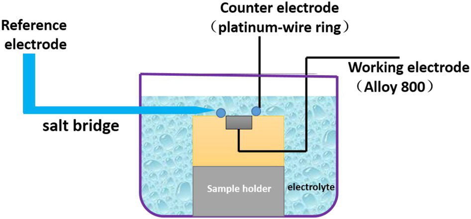
Image analysis
The area of the pitted surface was calculated using the following protocol. (1) The picture file was opened with Adobe Photoshop 2015 software. (2) The area of the metal part of the sample was selected using the ‘quick select’ tool, and pasted to a new layer. The original layer was set as invisible and the ‘histogram’ tool was used to obtain the number of pixels in the metal. (3) The image was divided into three channels (red, green, blue), one channel was chosen, and the other two channels were set as invisible. (4) The colour gradation of the image was changed to enable pitted areas to be easily distinguished from the passive metal background. (5) To make sure all pitting areas were selected and to remove interference from scratches and corrosion products, the ‘magic wand’ tool was used to select the area of pitting and the ‘quick select’ tool was used to add or delete interference. (6) The ‘histogram’ tool was used to obtain the total number of pixels corresponding to the pitted area.
X-ray photoelectron spectroscopy
After the polarisation test, the corrosion product within the pits was analysed by X-ray photoelectron spectroscopy (XPS) using an Axis-ULTRA spectrometer (Kratos Analytical) controlled by a SUN workstation to test the valance of the main elements in the corrosion product formed in solutions containing Cl– and  . Photoelectron emission was excited by an aluminium (monochromatised) source operated at 210 W with an initial photon energy of 1486.71 eV. The survey spectra were recorded in steps of 0.33 eV using 160 eV pass energy, and high-resolution spectra were taken in steps of 0.1 eV using 20 eV pass energy. The base pressure was approximately 5 × 10⁻¹⁰ Torr. Photoelectrons were collected at a take-off angle of 90° with respect to the sample surface. The C1 peak at 284.6 eV from adventitious carbon was used as a reference to correct for charging shifts. Specimens were cleaned using distilled water before each test.
Results and discussion
Pitting potential
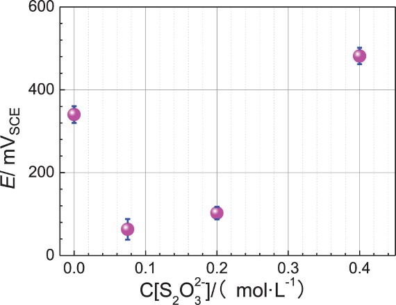
The polarisation curve of Alloy 800 in 0.6 mol L−1 NaCl containing various thiosulphate concentrations is shown in Figure 2. In all the curves, there exist ‘platforms’ that correspond to passive regions. As the potential moves in the anodic direction, the current increases gradually; a sudden increase in the current denotes passive film breakdown. As the polarisation potential becomes positive, the electric field in the passive layer/solution interface becomes higher accordingly; as a result, the dissolution rate of the passive film increases. In Figure 3, the evolution of breakdown potentials of Alloy 800 is shown as a function of thiosulphate ion concentration in 0.6 mol L−1 NaCl at room temperature. The pitting potential E p (the potential where pitting was first observed) depends highly on the thiosulphate concentration in the chloride solution. In the absence of thiosulphate, the E p in the chloride solution is about 320 mVSCE. The E p decreases to 90 mVSCE with the addition of 0.075 mol L−1 thiosulphate, suggesting that there is a combined effect between these two ions on film degradation. A further increase in thiosulphate concentration to 0.2 mol L−1 leads to an E p of 140 mVSCE; in this situation, thiosulphate and chloride ions still have a combined affect. However, the addition of 0.4 mol L−1 thiosulphate into 0.6 mol L− 1 NaCl results in an increased pitting potential of 470 mVSCE. In addition, some transient peaks (not shown) that are close to the pitting potential appear in the polarisation curves; they are characteristics of a metastable pitting process.
Polarisation curves of Alloy 800 in 0.6 mol L− 1 chloride solutions containing various concentration of thiosulphate; a scanning speed of 0.1667 mV s−1 was used at room temperature. The evolution of breakdown potentials of Alloy 800 as a function of thiosulphate ion concentrations in 0.6 mol L− 1 chloride solutions at room temperature.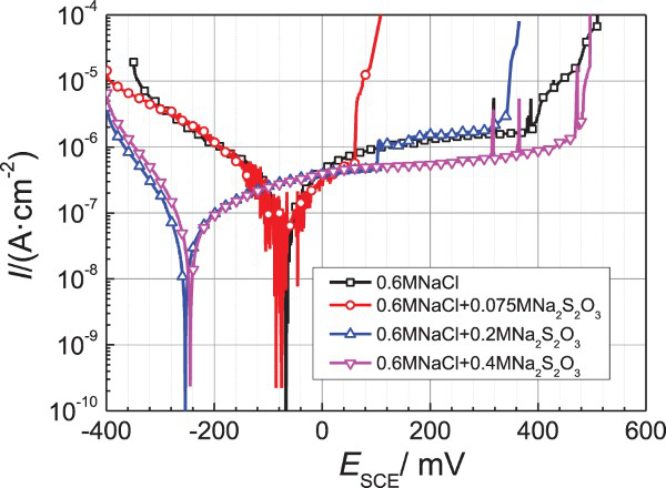
The E p is closely linked to the competitive adsorption of Alloy 800 of chloride and thiosulphate ions. It appears that thiosulphate is not aggressive enough to break down the passive film, and the presence of adsorbed chloride is necessary for pitting [18,19]. The E p is lowest in 0.6 mol L− 1 NaCl containing 0.075 mol L− 1 thiosulphate, because a small amount of thiosulphate does not affect the adsorption of chloride to a great extent. Chloride ions can easily break down passive film, but the film can be repassivated in the absence of thiosulphate. At a concentration of 0.075 mol L− 1, thiosulphate accumulates within the metastable pits by electromigration, and stabilises the metastable pits. At a thiosulphate concentration of 0.2 mol L− 1, the adsorption of chloride is assumed to be weakened. A higher E p is needed to breakdown the passive film, as a result, E p increases to about 150 mV. At a thiosulphate concentration of 0.4 mol L− 1 in 0.6 mol L− 1 NaCl, chloride adsorption is significantly weakened; consequently, the E p value is as high as 470 mVSCE, even higher than the E p in 0.6 mol L− 1 NaCl that contains no thiosulphate.
Pit growth rate
To compare the effect of thiosulphate concentration on the Alloy 800 pitting growth rate, all the specimens were polarised at 600 mVSCE for 700 s, and the current response was recorded (Figure 4). The current versus time curves at different concentrations of thiosulphate are shown in Figure 4. In chloride solution containing 0.075 mol L−1 thiosulphate, the current increases very quickly for 200 s due to the metal dissolution rate, then increases gradually, levelling off at 580 s. In chloride solution containing 0.2 mol L−1 thiosulphate, the current increases for 200 s, but at a slower rate than the increase observed at 0.075 mol L−1 thiosulphate, possibly indicating a slower pit propagation rate. In chloride solution containing 0.4 mol L−1 thiosulphate, the current increases slowly, levelling off at ∼500 s, suggesting that thiosulphate may accelerate the pitting growth rate. In 0.6 mol L−1 NaCl that contains no thiosulphate, the current increases slowly reaching about 20 mA cm–2 at 700 s, indicating that in the absence of thiosulphate the pitting growth rate is compromised.
Current responses of Alloy 800 under potentiostatic polarisation for about 700 s at room temperature.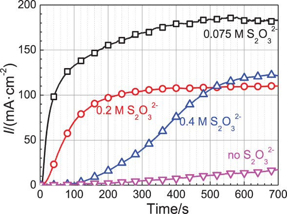
Corrosion morphology was synchronously recorded during the electrochemical measurements, as shown in Figures 5–8. Figure 5 shows Alloy 800 corrosion images at various time intervals in 0.6 mol L− 1 NaCl containing 0.075 mol L−1 thiosulphate. Many observable pits can be seen on the Alloy 800 surface at 30 s; at 60 s the pits have grown larger whereas the observable pit number has not increased much. As the polarisation time is prolonged to 90 s, the existing pits continue to enlarge, some corrosion products accumulate within the pits and other corrosion products enter into and are suspended in the solution.
In situ corrosion images of Alloy 800 in 0.6 mol L− 1 NaCl containing 0.075 mol L− 1 Na2S2O3 at room temperature. In situ corrosion images of Alloy 800 in 0.6 mol L− 1 NaCl containing 0.2 mol L− 1 Na2S2O3 at room temperature. In situ corrosion images of Alloy 800 in 0.6 mol L− 1 NaCl containing 0.4 mol L− 1 Na2S2O3 at room temperature. In situ corrosion images of Alloy 800 in 0.6 mol L− 1 NaCl.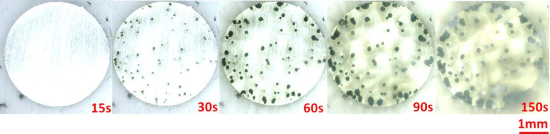
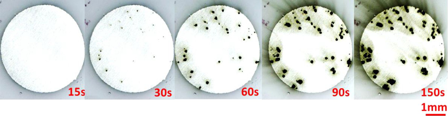
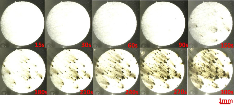
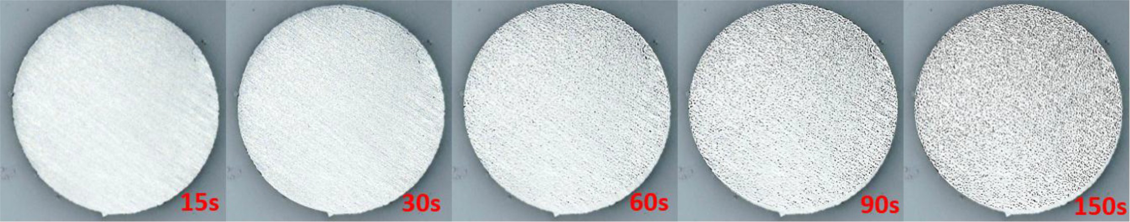
Figure 6 shows the corrosion images on Alloy 800 at various time intervals in 0.6 mol L− 1 NaCl containing 0.2 mol L−1 thiosulphate. The pitting growth rate is slower at 0.2 mol L−1 thiosulphate than at 0.075 mol L−1 thiosulphate. The number of pits after Alloy 800 is polarised for 30 s in 0.6 mol L− 1 NaCl containing 0.2 mol L−1 thiosulphate is fewer than the number of pits after Alloy 800 is polarised for 30 s in 0.6 mol L− 1 NaCl containing 0.075 mol L−1 thiosulphate. All ‘old’ pits formed at 30 s have grown larger at 60 s, and some new pits are generated. At longer times, the pits continue to propagate. Figure 7 shows the evolution of the corrosion morphology on Alloy 800 in 0.6 mol L− 1 NaCl containing 0.4 mol L−1 thiosulphate. No observable pits can be seen before 90 s, indicating that either there is a longer incubation period before pits are initiated or there is a slower pit growth rate so that the pit is too small to be observed optically at this magnification. After 150 s, some apparent pits have been formed on the Alloy 800 surface; the pits propagate gradually from 150 to 300 s. The observable pit number is less than the pit number observed in 0.6 mol L− 1 NaCl containing 0.2 mol L−1 thiosulphate.
The pit morphology on Alloy 800 in 0.6 mol L− 1 NaCl containing no thiosulphate is shown in Figure 8. The pit size is extremely small but the pit number is much larger than the pit numbers observed in solutions containing thiosulphate. The polarisation curve in Figure 2 shows that Alloy 800 is subject to metastable pitting, but such metastable pits do not tend to grow larger. Thus in 0.6 mol L− 1 NaCl in the absence of thiosulphate, pits with small size propagate.
Image analyses
Image analysis was employed to qualify the pitting growth rate in all the corrosion images. Figure 9 shows one example of a corrosion image after it was processed in Photoshop. The black colour represents the pitted regions and unpitted regions are white. As the polarisation time lengthens, the black dots become larger but the dot number does not significantly increase, indicating a true measure of pit growth rate.
Treated corrosion images used for calculation by Adobe Photoshop 2015 software (in 0.6 mol L− 1 chloride + 0.075 mol L− 1 thiosulphate).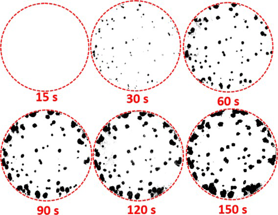
The ratios of pitted areas/unpitted areas on Alloy 800 at different exposure times were calculated and compared in various solutions, as shown in Figure 10(a). The growth rates of the ratios of pitted areas/unpitted areas increased in the following solution order: 0.6 mol L− 1 NaCl containing 0.075 mol L−1 thiosulphate > 0.6 M NaCl containing 0.2 mol L−1 thiosulphate > 0.6 M NaCl containing 0.4 mol L−1 thiosulphate > 0.6 M NaCl (with no added thiosulphate). That is, the presence of 0.075 mol L−1 thiosulphate in 0.6 mol L− 1 NaCl significantly increased the pitting growth rate on Alloy 800. The area ratio of pitted area/unpitted area in Alloy 800 is 12% at 150 s in 0.6 mol L− 1 NaCl containing 0.075 mol L−1 thiosulphate, and only 8% in 0.6 mol L− 1 NaCl containing 0.2 mol L−1 thiosulphate. Therefore, serious pitting corrosion occurs on Alloy 800 in chloride solution containing a small amount of thiosulphate.
Area ratio of pitted/unpitted area in NaCl solutions with/without thiosulphate ions.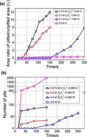
There was a ‘longer incubation period’ for observable pitting corrosion at 0.4 mol L−1 thiosulphate compared to other thiosulphate concentrations. In this case, the chloride adsorption was significantly weakened by thiosulphate ions, so the passive film was not easily broken down and there was an ‘incubation period’ for such breakdown. Passive film breakdown allowed thiosulphate to adsorb on these sites, accelerating the pitting propagation through the reduction of thiosulphate to elemental sulphur.
Figure 10(b) shows a comparison of pit numbers on Alloy 800 in various solutions. In 0.6 mol L− 1 NaCl with no thiosulphate added, the pit number on Alloy 800 reached 523 in 30 s, and increased to almost 2000 in 150 s. The pit number on Alloy 800 in 0.6 mol L− 1 NaCl containing 0.075 mol L−1 thiosulphate was higher than the pit number in 0.6 mol L− 1 NaCl containing 0.2 mol L−1 thiosulphate and the pit number in 0.6 mol L− 1 NaCl containing 0.4 mol L−1 thiosulphate, though the pit sizes were comparative in all these solutions. The results indicated that 0.6 mol L− 1 NaCl containing 0.075 mol L−1 thiosulphate demonstrated the most aggressive pitting corrosion on Alloy 800.
Pit corrosion mechanism
To further understand the mechanism of the corrosion observed on Alloy 800, XPS was used to analyse the corrosion product formed in 0.6 mol L− 1 chloride containing 0.075 mol L− 1 thiosulphate. Spectra for S2p, O1s, Fe2p3/2, Ni2p3/2, Cr2p3/2 are presented in Figure 11. Figure 11(a) shows the detailed spectra of the 2p level of suphfur, which is composed of S2−, S0, XPS spectra for corrosion products formed at the pitting potential in 0.6 mol L− 1 chloride + 0.075 mol L− 1 thiosulphate: (a) sulphur, (b) iron, (c) chromium, (d) nickel and (e) oxygen. and
and  peaks at energy levels within 160-172 eV, respectively.
  and
and  can likely be ascribed to
  in the thiosulphate solution.
  remains in the corrosion products and can be further oxidised when the Alloy 800 sample is exposed to air. S2– and S0 are detected due to the electrochemical reduction of
  within the pits to form sulphide (FeS, NiS) and elemental sulphur [18]. The
  anion can be enriched in the pits by electromigration.
  delivers elemental sulphur by elecrtroreduction and activates anodic dissolution of some pure metals, including Fe, Ni and Cr.
  can also disproportionate and consume acid, as shown below:
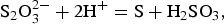

The Fe3+ peak at 710 eV in Figure 11(b) is likely related to the corrosion product FeOOH which forms on Fe–Cr–Ni alloys. The Fe2+ peak observed at 711.5 eV in Figure 11(b) is associated with FeS formed in the Alloy 800 pits. Cr3+ peaks are observed at 577.6 and 576.1 eV in Figure 11(c); these peaks are identified as Cr(OH)3 and Cr2S3, respectively. Figure 11(d) shows Ni2p spectra with NiS and NiOH peaks at 862 and 855 eV, respectively. Also significant is the broad range of stability of NiS over the range of pH (∼6.89) and electrical potential, which means that NiS is more stable than NiO [20]. The detailed spectra for the 1s level of oxygen shown in Figure 11(e) indicate that the peaks located at 529 and 531 eV are related to oxides and hydroxides. The XPS results indicate that the corrosion product is mainly composed of sulphide and elemental sulphur.
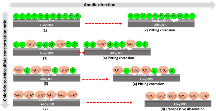
A schematic diagram of the pitting corrosion mechanism of Alloy 800 in chloride plus thiosulphate solutions is schematically shown in Figure 12. At a higher chloride/thiosulphate concentration ratio, Cl– adsorption is dominant, leading to metastable pitting of the passive layer of the alloy. The addition of A schematic diagram of factors influencing passivity degradation of Alloy 800 in solutions containing chloride + thiosulphate. ions into Cl– solutions lowered the pitting potential of the solution significantly. As long as the passive film breaks down to generate metastable pitting,
  can enter into this region by electromigration. After the passive film is broken down, a series of reactions occur in these regions. Metallic elements including Fe, Ni and Cr are oxidised to form either complexes of
  /Cl– or oxide in the pits. The localised pH value decreases within the pits.
  can be reduced to different sulphur species including
  and S–2, as confirmed by the XPS results. On the passive layer surface, the O2 in the solution can be protonated to form OH–. The pitting propagates on these active regions and causes the UNS N08800 failure. In addition, previous work found that
  can facilitate hydrogen entering into the passive layer [13], therefore,
  also induces hydrogen embrittlement in some cases [17].
Singh et al. [14] studied the effect of  addition to 0.6 mol L−1 NaCl on the metastable pitting of UNS S30403 and lean duplex stainless steel (LDX2101, UNS S32101). They found that the addition of
  stabilised metastable pit growth and promoted pitting on the metals. Moayed et al. [21] studied the effect of
  ion on the pitting corrosion of AISI 316 stainless steel in 0.1 mol L−1 NaCl. The authors claimed that the
  addition increased pit initiation susceptibility and facilitated the transition of metastable pitting to stable pitting. We found that in 0.6 mol L−1 NaCl, the addition of 0.075 or 0.2 mol L−1
  lowered the pitting potential (Figure 3) of the solution; the pitting potential reached a minimum value when the
  concentration was 0.075 mol L−1. As the
  concentration was increased to 0.4 mol L−1, the potential increased and we propose that the adsorption of Cl– ions weakened and the pitting potential increased. A similar phenomenon was reported by Newman [17].
At lower chloride/thiosulphate concentration ratios,  adsorption is dominant and the adsorption of Cl– is weakened. As a result, the passive film cannot easily be broken down by Cl–. In our previous work [16, we observed that no pits formed on the Alloy 800 surface in solutions if the chloride/thiosulphate concentration ratio is very low.
Conclusions
An investigation of pitting growth rates on Alloy 800 in chloride solutions containing various thiosulphate concentrations led to the following conclusions.
Image analyses is an effective way to identify the pitting growth rate on Alloy 800. Thiosulphate concentrations in chloride solutions significantly affect the pitting growth rate, the addition of 0.075 or 0.2 mol L− 1 thiosulphate to 0.6 mol L− 1 NaCl lowered the pitting potential of the solution and increased the pitting growth rate on Alloy 800. A combined effect of chloride and thiosulphate ions on passive film degradation appeared only when the chloride adsorption was dominant. Thiosulphate decomposed to elemental sulphur inside pits on Alloy 800, accelerating the pitting growth rate.