






Abstract
Alternating pyrolytic carbon/boron nitride (PyC/BN)n multilayer coatings were applied to the KD–II silicon carbide (SiC) fibres by chemical vapour deposition technique to fabricate continuous SiC fibre-reinforced SiC matrix (SiCf/SiC) composites with improved flexural strength and fracture toughness. Three-dimensional SiCf/SiC composites with different interfaces were fabricated by polymer infiltration and pyrolysis process. The microstructure of the coating was characterised by scanning electron microscopy, X–photoelectron spectroscopy and transmission electron microscopy. The interfacial shear strength was determined by the single-fibre push-out test. Single-edge notched beam (SENB) test and three-point bending test were used to evaluate the influence of multilayer interfaces on the mechanical properties of SiCf/SiC composites. The results indicated that the (PyC/BN)n multilayer interface led to optimum flexural strength and fracture toughness of 566.0 MPa and 21.5 MPa m1/2, respectively, thus the fracture toughness of the composites was significantly improved.
Introduction
Silicon carbide fibres-reinforced silicon carbide matrix (SiCf/SiC) composites exhibit numerous advantages as high temperature structural materials in aerospace for their excellent performance and outstanding properties, including low density, high resistance against oxidation, high specific strength/modulus and stability at high temperature. Moreover, SiCf/SiC composites are also promising candidate materials for applications in fusion energy systems due to their corrosion resistance, low induced radioactivity, rapid decay of activity and low afterheat [1-4].
It is well known that the fibre–matrix interfacial domain is a decisive constituent of fibre-reinforced ceramic matrices [5]. Depending on the characteristics of this domain, the composites are either a brittle ceramic or a damage-tolerant composite. Thus, interface is a critical link in ceramic matrix composites. The major functions of interface in composites include the protection of fibres against corrosion and fracture, transfer of load between fibre and matrix, and arrest and deflection of crack propagation in the matrix [6-8]. Boron nitride (BN) and pyrolytic carbon (PyC) are the two most common and effective interface materials attributed to their high melting point, excellent thermal conductivity, corrosion resistance, high temperature stability, high thermal shock resistance and simple process conditions [3,913]. So far, extensive research efforts have been devoted to investigate the single layer PyC interface and single layer BN interface [1416]. However, both PyC and BN have advantages as well they impose limitations. For example, PyC interface is oxidation prone; therefore, the high-temperature lifetime of SiCf/SiC composites with a PyC interface is strongly limited. Moreover, BN interface is unsuitable for the nuclear field [1719]. Therefore, multilayered approach involving the combination of both PyC and BN is clearly desirable to take advantage of their beneficial properties. The self-healing ability of multilayer interface is efficient in preventing oxygen from diffusing into fibre surface, which allows SiCf/SiC composites to have an extended life time at high temperatures in oxidising environment [20]. Therefore, it becomes possible for SiCf/SiC composites to have excellent overall properties [21]. The (PyC/SiC)n and (BN/SiC)n multilayer interface in SiCf/SiC composites has been studied extensively [2227]; however, investigations on the SiCf/SiC composites with (PyC/BN)n multilayer interfaces have rarely been reported.
The main objective of the present study was to investigate the influences of a (PyC/BN)n multilayer interface on the mechanical properties of SiC fibre and SiCf/SiC composites. In this study, the as-received KD–II SiC fibres [28] were first coated with PyC and BN multilayer, and then SiCf/SiC composites with different interfaces were prepared by the polymer infiltration and pyrolysis (PIP) method. The microstructure evolution of the interface was observed and the morphology of the composites was characterised. The effect of different coatings on the mechanical properties of SiC fibre was evaluated by single-filament tensile strength tests. Flexural strength, fracture toughness and interfacial shear strength were used to evaluate the influences of interfaces on the mechanical properties of SiCf/SiC composites.
Materials and methods
Sample preparation
General properties of the as-received KD–II SiC fibres.

Parameters of 3D four-directional prefabricated piece.
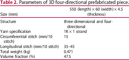
A mixture of 2,4,6,8-tetravinyl-2,4,6,8-tetramethylcyclotetrasiloxane (V4) and liquid polycarbosilane (a mixture of LPCS and V4 with a certain weight ratio (LPVCS), viscosity of 20 MPa s at 25°C, provided by NUDT) in the weight ratio mixture of 0.6:1 was used as a ceramic precursor [29,30]. Before the PIP process, fibre preforms were coated with (PyC/BN)n multilayer coatings by low pressure chemical vapour deposition process. Propylene was employed as the precursor of PyC; and boron trichloride and ammonia were employed for BN. PyC coating was prepared at 960°C using N2 as a carrier gas with a total pressure of 3 kPa and a deposition time of 5 h. The flow rates of propylene and N2 were fixed at 4 and 3 L min–1, respectively. BN coating was prepared at 600°C using N2 and H2 as diluent gases with a total pressure of 3 kPa and a deposition time of 1 h. The flow rate of boron trichloride, ammonia, N2 and H2 was fixed at 10, 30, 100 and 100 mL min–1, respectively.
SiCf/SiC composites were fabricated by PIP process. The flow chart of the fabrication process of SiCf/SiC composites is shown in Figure 1. The coated preform was impregnated with LPVCS by vacuum infiltration method. A crosslinking step (before PIP, after infiltration) is necessary for the preform infiltrated with the LPVCS precursor. In this study, the LPVCS precursor cross-linked at 300°C for 1 h under nitrogen with a heating rate of 1°C min–1. The crosslinking step was followed by the PIP process (for the preform infiltrated with LPVCS precursor) with the same heating rate and hold time. A pressure-assisted (2 MPa) curing process was applied after the first impregnation. Then the preforms were heated up to 1100°C with a heating rate of 10°C min–1 and a duration of 30 min in an inert argon atmosphere. The procedure of infiltration and PIP was repeated nine times till the weight increment of the composites was less than 1%.
Flow chart of the fabrication process of SiCf/SiC composites.
In this study, SiC fibre and SiCf/SiC composites with different interfaces were denoted according to the composition of interfaces as K–C, K–B, K–CB, K–BC, K–CBC, K–BCB, KL–C, KL–B, KL–CB, KL–BC, KL–CBC and KL–BCB, respectively, where ‘K’ indicates KD–II SiC fibre, ‘L’ represents precursor LPVCS, ‘B’ represents a chemical vapor deposition (CVD) BN interface layer and ‘C’ indicates a PyC interface layer.
Evaluation of properties
The bulk density and open porosity of the SiCf/SiC composites were determined by Archimedes’ principle using kerosene as the immersion medium according to ASTM D792–00. The flexural strength of the SiCf/SiC composites was measured by the three-point bending test (ASTM C1341–06), while the fracture toughness of SiCf/SiC composites was measured by the SENB test (ASTM E1820–11E2). The dimension of the samples for the three-point bending test was 55 × 4 × 3 mm3 with a span of 50 mm and a crosshead speed of 0.5 mm min–1. The size of the specimen for the fracture toughness test was 35 × 6 × 3 mm3 with a span of 30 mm, a notch depth of 3 mm and a crosshead speed of 0.05 mm min–1. Five specimens were tested to estimate the scatter in the mechanical tests. Single-filament tensile strength of the SiC fibres with different coatings was determined using an electronic single- fibre strength tester (Testometrix Micro 350, Greater Manchester, U.K.) according to ASTM D3379–75. Seventy specimens were tested to estimate the scatter in the single-filament tensile strength tests. The interfacial shear strength of the SiCf/SiC composites was evaluated by single-fibre push-out tests which were performed using a HIT–100 Single-Fibre Push-out Test System (SFPTS, Harbin, China) [22]. The dimension of sample for single-fibre push-out test was 2 × 2 mm2 with a mechanical shearing thickness of 100–150 μm. The sketch map of SFPTS and the morphology of the samples are shown in Figure 2.
(a) Sketch map of SFPTS, (b) obverse side of the sample and (c) reverse side of the sample.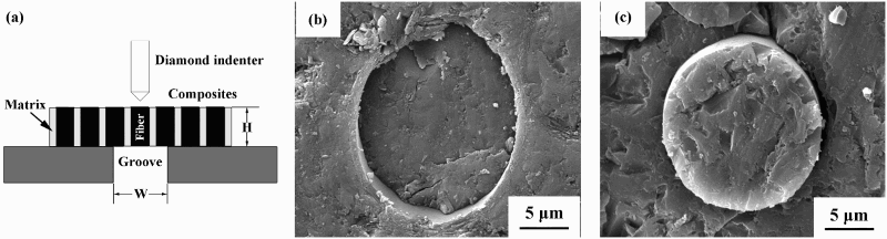
Scanning electron microscopy (SEM, Hitachi S4800–II FESEM, Tokyo, Japan) was employed to examine the fracture surfaces of the SiC fibres and SiCf/SiC composites, while energy-dispersive X-ray photoelectron spectroscopy (XPS, EscaLab–250Xi, Massachusetts, American) was used to analyse the composition, content and chemical bond energy of BN coating. The bonding state of turbostratic BN (t-BN) was measured by Fourier transform infrared (FTIR) spectroscopy and the crystal state of the t-BN was measured by X–ray diffraction (XRD, RIGAKU, Tokyo, Japan). The selected area electron defraction (SAED) of t-BN was observed by transmission electron microscopy (, Tecnai GF30 field emission transmission electron microscope, FEI Company, Hillsboro, American).
Results and discussions
Microstructure of SiC fibres with different coatings
The results of XPS, SAED, XRD and FTIR analysis of single BN coating are shown in Figure 3 and Table 3. The XPS spectrum of B element in the BN coating is shown in Figure 3(a). The SAED image, XRD patterns and FTIR spectrum of the BN coating are shown in Figures 3(b–d) respectively.
Analysis of BN coating: (a) XPS spectrum, (b) SAED image, (c) XRD spectrum and (d) FTIR spectrum. Atom fractions of CVD BN coating by XPS analysis.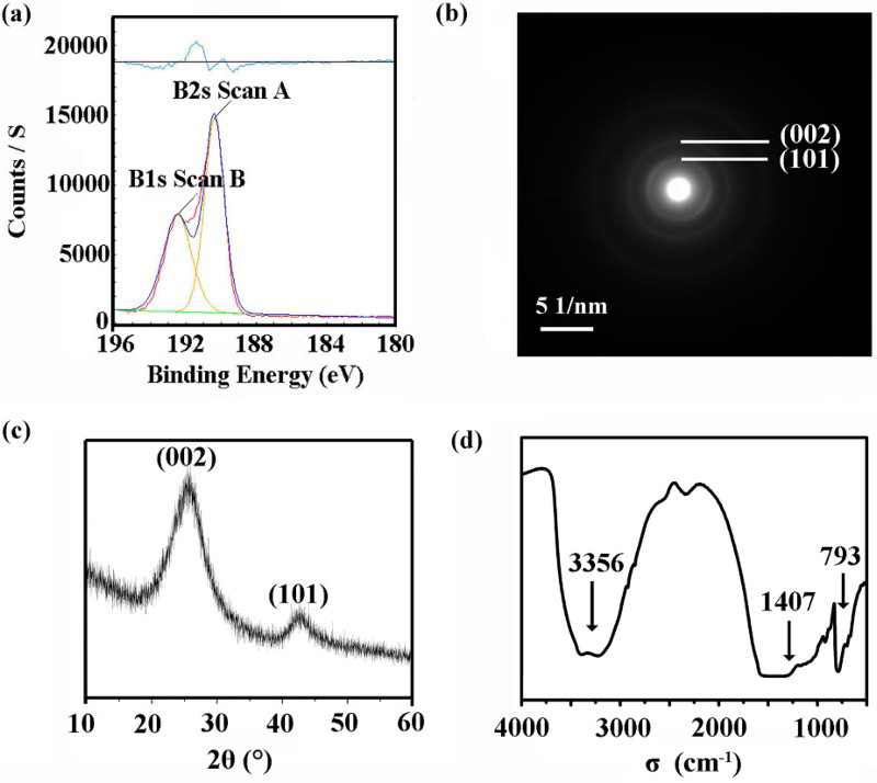
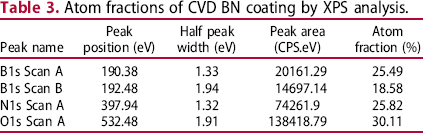
XPS is a surface analysis technology. The values listed in Table 3 indicate that oxygen content was extremely high in BN coating, with an atom fraction of 30.11%, which could be attributed to the fact that BN coating prepared under relatively low deposition temperature had poor stability and was likely to be hydrolysed. Figure 3(a) reveals the existence of two characteristic peaks for the B element with the binding energies at 190.38 and 192.48 eV. These two peaks, respectively, match BN and B2O3, which indicates that some parts of the surface of the BN coating were hydrolysed. The XRD spectrum shows that 2θ corresponds to 26.86° and 42.3°, where the diffraction peaks are, respectively, attributed to the appearance of BN (002) (d = 01344 nm) and (101) (d = 01213 nm) planes; however, the diffraction peaks are not sharp enough, which indicates the poor crystallinity of BN coating. Figure 3(d) exhibits the FTIR spectrum showing the existence of three absorption peaks with the wave numbers of 3356, 1407 and 793 cm–1. The peak at 793 cm–1 corresponds to the bending vibration of out-of-plane B–N–B bending and that at 1407 cm–1 corresponds to the stretching vibration of in-plane B–N stretching. The prepared BN has poor crystallinity; therefore, it can easily get hydrolysed. Thus, the peak at 3356 cm–1 corresponds to the stretching vibration of O–H bond in the water. The SAED image in Figure 3(b) also shows the poor crystallinity of the BN coating. Figure 3(b) clearly exhibits the difference between two diffraction rings of the BN coating, and the corresponding diffraction ring radius is 2.85 and 4.70 (1/nm), respectively. According to the Bragg formula, the diffraction angles 2θ of the diffraction rings were calculated to be 25.7° and 42.8°, which is consistent with XRD results. All the above-mentioned results support that the BN coating obtained via CVD is t-BN. The stability of BN coating increases with the increase in the preparation time [17,23,31]. The acceleration in the deposition rate was the main reason for the poor homogeneity of the fibre surface coating in the preform. Therefore, uniform BN coating was prepared under low temperature condition in this study, and subsequent heat treatment in an atmosphere of N2 could improve the stability of BN coating. As fibre prepared with coating would finally be used to fabricate PIP–SiCf/SiC composites, the subsequent PIP process of PIP method was determined to be equivalent to heat treatment on BN coating.
SEM images of single PyC coating, single BN coating and (PyC/BN)n multilayer interfaces on the surface of SiC fibre are shown in Figure 4.
Morphology of monolayer coating on KD–II SiC fibre surface (a) C, (b) B, (c) C B, (d) BC, (e) CBC and (f) BCB.
Figure 4 clearly provides the evidence that the thickness of single CVD BN coating and single PyC coating on the SiC fibre surface is approximately 200–300 nm upon technological parameter control with excellent homogeneity. BN coating is relatively smooth; however, PyC coating shows the presence of local granule protrusion. Within the multilayer coating, thickness of BN coating is about 200 nm. However, PyC coatings were not prepared in the same experiment; therefore, their thickness was different corresponding to about 200–600 nm. Multilayer coatings on the surface of SiC fibres are presented in Figures 4(c–f). Owing to the sensitivity of the CVD BN coatings, the morphology of the coatings in Figures 4(c–f) appears to be incomplete. In the multilayer coatings, the order of the preparation of coatings influences the thickness of the coatings, thus coatings with different thickness are obtained even if they are fabricated under the same process conditions.
A (PyC/BN)n multilayer interface was utilised to prepare a SiCf/SiC composite material in this study. Furthermore, the effects of various interface combinations on the mechanical properties of SiC fibre and SiCf/SiC composites were investigated.
Properties of SiCf/SiC composites
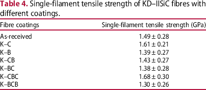
Single-filament tensile strength of KD–IISiC fibres with different coatings.
Properties of SiCf/SiC composites with different coating groups.

The KL–B composites exhibited the highest density (2.31 g cm–3) and the smallest open porosity (2.9%). The other SiCf/SiC composites had almost similar densities and open porosities (approximately 2.20 g cm–3 and 3.5%, respectively). However, the flexural strength of the KL–B composites was the worst (376.0 MPa). The poor mechanical properties of SiCf/SiC composites reinforced with the CVD BN-coated KD–II fibres prepared by PIP process were attributed to strong fibre–matrix interface bonding (with an interfacial shear strength of 128.3 MPa) [26]. When the bonding between fibre and matrix is too strong, most of the cracks in the matrix propagate to fibres and cut through them, leaving a smooth fracture surface. This finding is expected because the high near–tip stress of the propagated matrix cracks could not be efficiently dissipated in this composite [22]. The KL–CB composites exhibited the highest flexural strength and fracture toughness (566.0 MPa and 19.3 MPa m1/2, respectively). The mechanical properties of KL–C, KL–BC, KL–CBC and KL–BCB composites were almost similar (the flexural strength ranged from 426.8 to 479.8 MPa, and the fracture toughness was in the range of 15.8–19.3 MPa m1/2). The interfacial shear strength of the KL–BC composites was the lowest (27.0 MPa); however, those of KL–C, KL–CB, KL–CBC and KL–BCB were approximately equal (37.5–40.7 MPa). Compared to the non-interface SiCf/SiC composites (fracture toughness is 6.7 MPa m1/2) [26], the fracture toughness of the SiCf/SiC composites prepared in this study was higher because the interface was properly regulated and the strong interface between the fibres and the matrix was effectively prevented.
Typical stress–strain curves recorded during the three-point bending test of SiCf/SiC composites with different interfaces are shown in Figure 5, which reveal the failure behaviour of the composites. The stress–strain curves of SiCf/SiC composites with different interfaces exhibit initial linear regions followed by nonlinear stages up to the ultimate flexural strength. Large amounts of fracture energy were consumed in the composites after the flexural strength reached a maximum value, indicating that toughening mechanisms, such as interface debonding, crack deflection, crack branching, fibre bridging and fibre pull-out played important roles during the composite fracture.
Typical stress–strain curves recorded during the three-point bending test of SiCf/SiC composites with different interfaces.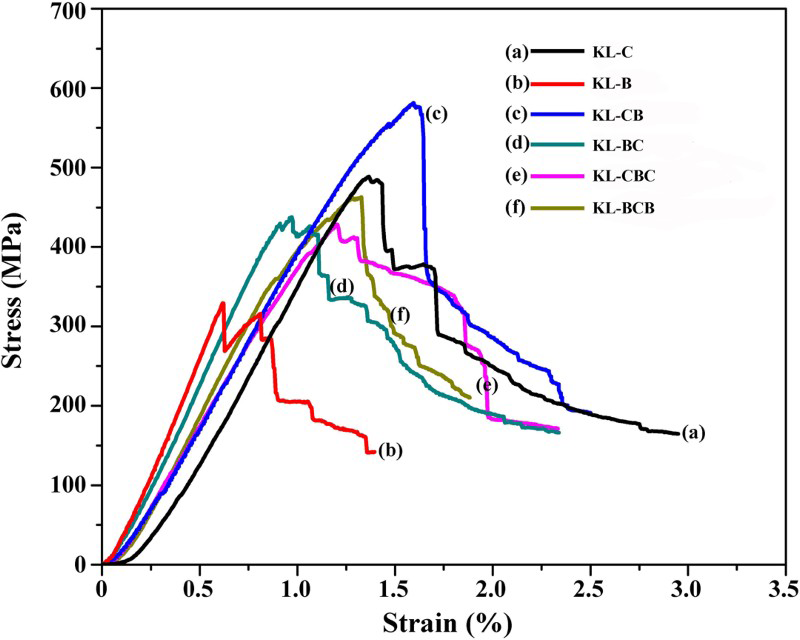
Figure 6 shows fracture morphologies of the SiCf/SiC composites with different interfaces. Figure 6(a–f) shows the presence of the pulled-out fibres on the fracture surface of the composites, which verifies the test data listed in Table 5 and the curves shown in Figure 5. The residues of interface material attached to the pull-out fibres can be seen in Figures 6(c–f). The residues show the existence of a certain type of moderate binding force between interface and both matrix and fibre. Interface was damaged in the process of fracture; therefore, some energy was consumed when interface was broken apart from matrix and fibres, indicating that multilayer interfaces are beneficial to preventing the composites from brittle fracture.
Fracture morphologies of the SiCf/SiC composites with different interfaces (a) KL–C, (b) KL–B, (c) KL–CB, (d) KL–BC, (e) KL–CBC and (f) KL–BCB.
The mechanical properties of SiCf/SiC composites reinforced with the CVD BN-coated KD–II fibres were found to be the worst, which was likely due to a strong fibre–matrix interface bonding. The CVD BN coating prepared at low temperature exhibited poor crystallinity and hydrolytic stability; therefore, it could be partly hydrolysed before the preparation of the SiCf/SiC composites. This resulted in the formation of the direct matrix–to–fibre contact in a few areas. Consequently, too strong interface bonding formed in KL–B composites resulted in the highest shear strength of interface and the worst mechanical properties. Following the hydrolysis of the sublayers of KL–BC and KL–BCB composites, the decreased contact area between fibres and coating and the defects on the coating resulted in a weaker binding force to fibres, so that the load transmission was consequently less efficient. Therefore, KL–BC and KL–BCB composites exhibited worse mechanical properties, respectively, than KL–C and KL–CB composites. Besides, hydrolysis led to the formation of holes on the outer BN coating of KL–CB and KL–BCB composites, which allowed for the insertion of the SiC matrix in these holes so as to form a mechanic interlocking structure. This type of structure will enable efficient consumption of energy in the fracture process of composites, which is helpful for strengthening the mechanical properties of composites. Therefore, KL–CB and KL–BCB composites exhibited greater mechanical properties, respectively, than KL–C and KL–BC composites. In KL–CBC composites, hydrolysis in the BN sublayer in the middle of interface led to less efficient load transmission. Thus, KL–CBC composites showed worse mechanical properties than KL–C composites. Furthermore, the two PyC coatings in KL–CBC composites were not prepared in the same experiment, which resulted in the difference between their thicknesses. The inner PyC coating was thicker (about 400 nm), which could be another reason for the worse mechanical properties.
Conclusions
In this study, alternating (PyC/BN)n multilayer coatings were applied to the KD–II SiC fibres by chemical vapour deposition technique to fabricate continuous SiCf/SiC composites with improved flexural strength and fracture toughness.
The poor mechanical properties of SiCf/SiC composites reinforced with the CVD BN-coated KD–II SiC fibres prepared by PIP process were attributed to a strong fibre–matrix interface bonding. CVD BN coating prepared at low temperature was poorly crystallised. This coating could be partly hydrolysed before the preparation of the SiCf/SiC composites. The KL–CB composites exhibited the optimal mechanical properties. The average flexural strength and fracture toughness of the single PyC-coated composites were 566.0 MPa and 19.3 MPa m1/2, respectively. The presence of mechanically interlocked structures formed at the interface of KL–CB (CVD BN and SiC matrix) was a possible reason that KL–CB possessed the optimal mechanical properties.
Undeniably, a lot more systematic explorations are demanded to investigate optimisation of the preparation of BN interface, which will be pursued in future. We suspect that stable BN interface (coating) can be obtained by a heat treatment at high temperature.
Footnotes
Disclosure statement
No potential conflict of interest was reported by the authors.