
Abstract
This paper develops a numerical model that contained random lip-shaped matrix cracks based on the maximum energy release rate criterion for the prediction of failure progress of Continuous Fibre-reinforced Ceramic Matrix Composites (CFCC) under transverse tension. Fibre distribution layout is created based on the actual microstructure and the Random Sequential Adsorption algorithm is used to generate the distribution of lip-shaped matrix cracks. The influence of the lip-shaped matrix crack distribution and crack density on the failure progress and stress–strain response was investigated. It was found that the onset of damage initiation commenced from the lip-shaped matrix crack when the interface fracture energy was smaller than the critical interface fracture energy. The failure progress and the predicted results were in good agreement with the experimental results. The different matrix cracks distribution affected the failure progress. Finally, the tensile strength and the elastic modulus both decreased with the crack density increasing.
Introduction
Continuous Fibre-reinforced Ceramic Matrix Composites (CFCC) has become one of the most popular materials for high-temperature parts of aeroengines in the past decades [1]. CFCC is known for the high strength and high toughness, especially when critical strain is reached, they are prone to non-catastrophic fracture. However, fibre clusters and matrix impurities, such as voids and microcracks, are typically observed. The complexity of the microstructure leads to complex damage mechanisms, including matrix cracks, interface debonding and the interaction between two damage mechanisms. Therefore, investigation of the damage mechanisms of the CFCC under transverse tension plays an important role in the mechanical properties and failure modes of the overall structure of CFCC [2].
Many numerical methods are proposed to simulate the damage mechanisms of CFCC with a weak interface under transverse tension. By different numerical methods, different Representative Volume Element (RVE) models are established. Initially, a single fiber surrounded by matrix material with a fiber volume fraction was usually used to study the properties of fibre-reinforced composites. (Lou Juhong et al. [3] and MJ Mahmoodia et al. [4]). The boundary element method (BEM) was used by E. Correa et al. [5] to suggest that results in the mesoscale level had a clear connection with the results at the macroscale level. Furthermore, E. Correa et al. [5] showed that although the single fibre model was able to provide qualitative information for crack initiation and crack propagation, it was not enough to quantitatively explore the relationship between the micromechanical and the macro-mechanical parameters, which is why multiple-fibres models were worthwhile to predict accurately the macro-mechanical behavior of fibre-reinforced composite materials. D. Trias et al. [6] compared the stress and strain distributions between the periodic model and the random model. They revealed that the periodic model would be used to predict effective performance, but the random model must be considered for local damage processes such as interface debonding or macroscopic matrix cracks. Random distribution and aggregation of fibres caused obvious stress concentration, which affected the predicted results of the transverse tensile properties of fibre-reinforced composites [7,8]. Fully characterising the actual microstructure of fibre-reinforced composite materials benefited the failure behavior simulation more accurately (Carl R et al. [9], Romanov V et al. [10]). As a result of previous researches, a RVE model with random distribution and aggregation of fibres, generated from the actual microstructure, played a key role in analysing the initiation and damage propagation. Many researchers have investigated the influence of the model size (Corso F D [11], Soni G [12] and Kanit T [13]). Kanit T [13] pointed out that to ensure the accuracy of the simulation results, the volume of the RVE model should not be too small. Carlos González et al. [14] showed that only the RVE model that contained more than 30 fibres could accurately characterise the overall performance of composites. Many multiple-fibre models have been developed to explore the failure process and predict the performance of fibre-reinforced composites under transverse tension. Leying Song [15] proposed a finite element-based phase-field method to reveal the interface stress distribution and interface cracking stress. This method was used to explore the transverse tensile failure process of UD fibre-reinforced composites. Meyer P [2] used the crack band method to establish a micromechanical numerical fracture model of CFCC, which was applied to predict the failure progress of CFCC. The crack band method yet required predefined crack paths. Cohesive damage (XFEM) and adhesive damage (cohesive surface) based on the Cohesive Zone Modelling method have been proposed to simulate matrix damage and interface debonding respectively. The advantage of the Cohesive Zone Modeling method is that there is no need to predefine the crack path to simulate the evolution of microscopic damage [16]. Bhuiyan FH [17] indicated that the microstructure had little effect on the transverse elastic modulus of UD composites, but had a great influence on the transverse tensile strength. Peng Pai et al. [18] used the interface cohesion unit model combined with the matrix Drucker-Prager elastoplastic model to predict the transverse tensile strength of fibre-reinforced composites. Yang L [19] discussed the effects of interfacial properties on the damage behaviour of the composites, using the extended Drucker-Prager model and cohesive zone model. It was found that the influence of the interfacial strength on the tensile strength of composites was significant, compared with the interfacial stiffness and fracture energy. According to these former researches, it was generally considered that the damage commenced from the interface [4]. When the interfacial crack expanded along the interface to a finite size, it kinked into the matrix, and finally, macrostructure matrix cracks caused the complete fracture [20]. Meyer P, et al. [2] concluded that matrix cracks with different shapes and different propagation directions affected the mechanical behaviour of CFCC. The increase in crack density significantly reduced the transverse elastic modulus and transverse Poisson's ratio of fibre-reinforced materials, which made it difficult for composite materials to withstand transverse tensile loads [21]. In addition to the crack density, the crack shape can affect the material elastic moduli indicated by Huang H [22].
However, although interfacial crack and matrix cracks of CFCC under transverse tension were investigated over decades, few researchers have addressed the influence of microcracks in the matrix on the failure process under transverse tension. It was observed that cracks appeared in the matrix under very small strain conditions in unidirectional CMC, layered CMC, or woven CMC tests [23,24]. The existence of matrix microcracks related to stress concentration in the matrix, which differed the shape and propagation direction of the macroscopic matrix crack. Many researchers considered matrix cracks as regular-shaped cracks such as linear, triangular, or elliptical [25,26]. But the actual matrix cracks of ceramic matrix composites are much more complicated, which were described as ‘large middle, small ends’ curved polygonal cracks in the matrix of CFCC [27].
This paper introduced a numerical model that contained random lip-shaped matrix cracks to evaluate the complex failure mechanisms of CFCC under transverse tension. The matrix crack was modelled by the lip-shaped matrix crack. The criterion of the onset of matrix cracking was investigated using the energy release rate criterion and the interface was incorporating as a cohesive surface between matrix and fibres. Then the failure process of CFCC under transverse tension was implemented in Abaqus. The transverse failure process of CFCC considered the lip-shaped cracks was illustrated and compared with the experimental results. Finally, the influence of various parameters on the transverse tensile mechanical behaviour of CFCC was further analysed.
Stress analysis
Matrix model
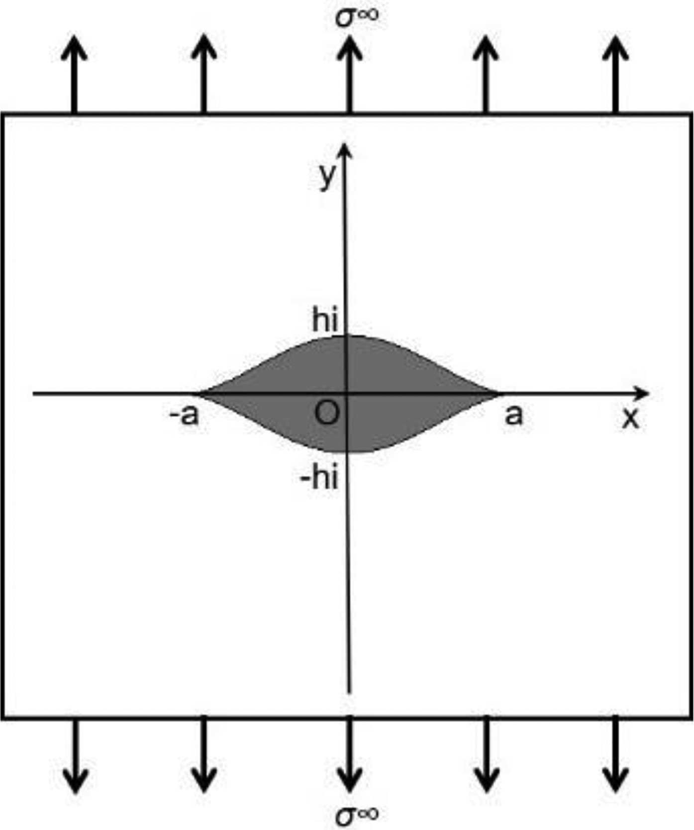
Microcracks of C/SiC composites exhibit curved edge polygon with a certain height and two tips as shown in Figure 1 [28]. The matrix crack of CFCC can be modelled by the lip-shaped crack. Considering one lip-shaped crack existing in the centre of the infinite matrix, geometric characteristics of the lip-shaped crack can be defined by the following parameters: half-length a, half-width h and width-length ratio β = h/a, as shown in Figure 2. The crack boundary L sets as a free boundary and a uniform infinity stress σ∞ along the y-axis is imposed on the infinite matrix.
Matrix cracks of CFCC [28]. Lip-shaped crack model under transverse tensile.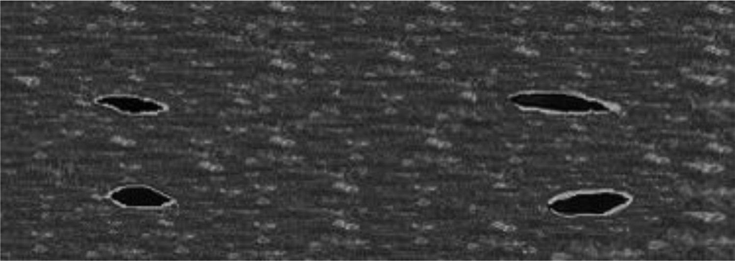
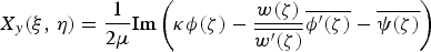
The stress components
 and displacement components
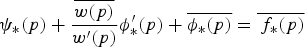
 can be decomposed into two complex stress functions ϕ(Z) and ψ(Z) as:

 is a complex variable on the crack plane,
 ,
,
 , E is the elastic modulus of the matrix,
 is the Poisson ratio.
Because of the surface force Tx = Ty = 0 on the crack boundary L, the stress boundary condition at arbitrary point z = x + iy on the crack boundary L is expressed as:

To solve the stress field and strain field of an infinite plane contained cracks under transverse tension, the analytical solutions of two complex potential functions need to satisfy the boundary condition (4).
Since the radius of curvature at the end of the crack contour is zero, undergoing a sudden change, it is more difficult to solve directly on the crack plane
 . Therefore, the conformal mapping function is introduced to map the inner area of the lip-shaped crack to the inside of the unit circle on the plane
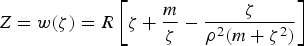
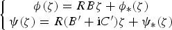
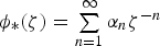
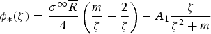
 , and complex stress functions ϕ(z) and ψ(z) become complex stress functions ϕ(ζ) and ψ(ζ) on the ζ-plane, transforming the crack plane strain problem into the plane strain problem of the unit circle. Not only can the solution process be simplified, but also the uniqueness and completeness of the solution can be guaranteed. The conformal mapping [29] used is as follows:
 ,
,
 ,
,
 ,
,
 ,
,
 ,
,
 ,
,
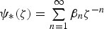
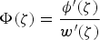
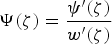
 . According to the theory developed by Muskhelishvili [30], the general expression of these complex stress functions on the ζ-plane are
 ,
,
 ,
,
 ,
,
 ,
,
 ,
,
 and
and
 are complex constants.
The stress components
 and displacement components
 can be rewritten by substituting Equation (5) into Equations (1) and (2) as follows:
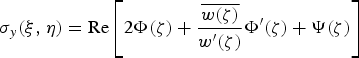
 ,
,
 .
.
The stress boundary condition and its conjugation on an arbitrary point on the unit circle, p = eiθ, can be expressed by substituting Equation (5) into Equations (3) and taking its conjugate, as follows:
 .
.
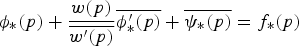
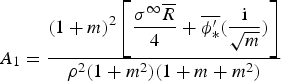
Based on the property of Cauchy integral [30], the expressions of
where
 and
and
 can be obtained by integrating and simplifying Equations (8) and (9), as shown in the following equation:

 ,
,
 ,
,
 ,
,
 .
.

 and displacement component
 can be obtained in terms of ξ and η. Finally, substituting the inverse mapping
 of conformal mapping (5), the stress component
 and displacement component
 on the crack plane
 is expressed in the terms of x and y.
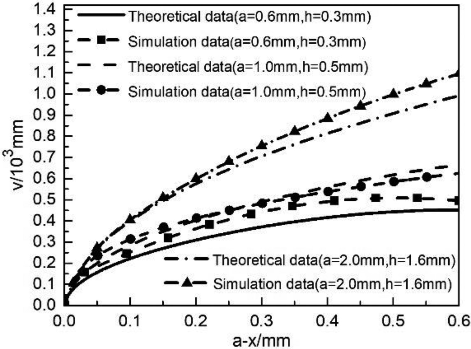
Figures 3 and 4 showed the comparison of theoretical data and simulation data of stress field and displacement field at the crack tip for cracks of different shapes (different β) or different sizes (same β) under transverse tension, respectively. The theoretical data for most areas were quite similar to the simulation data except for the area very close to the crack tip caused by the singularity of the crack tip. Besides, when crack was relatively small, the finite element is affected by the mesh, and the simulation data deviated from the theoretical data. The results of Figures 3 and 4 proved that theoretical solutions of the stress field and displacement field for the lip-shaped crack model were effective.
Comparison of stress field theoretical data and simulation data for cracks of different shapes and sizes. Comparison of displacement field theoretical data and simulation data for cracks of different shapes and sizes.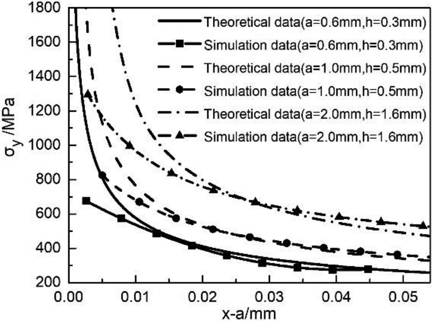
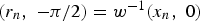
As shown in Figure 1, the initial length of the crack is a, and the final length of the crack after propagation is assumed as a+Δa. While the surface force on the crack propagation section disappears, the new opening displacement is
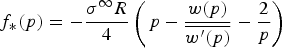
 . The maximum energy release rate at the lip-shaped crack tip can be rewritten in the form of Riemann sum:

 ,
,
 , w−1 is the inverse mapping of conformal mapping (5).
Since the lip-shaped crack under transverse tension only is the mode I cracks, when the maximum energy release rate of the crack tip satisfies G > GIC, the lip-shaped matrix crack will propagate along the direction of the crack tip.
Interface cohesive model
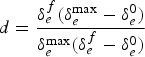
A 4-node cohesion element (COH2D4) was inserted into the zero-thickness matrix/fibre interface to simulate the continuous debonding behaviour of the interface under loading conditions. The mechanical behaviour of these elements is controlled by the traction-separation law. When the crack is not completely cracked, the stress σ increases linearly with the increase of the opening displacement δ in absence of damage and, therefore, the traction-separation law can be written as:
Schematic of the traction-separation law.
 and
and
 are the maximum normal stress and maximum tangential stress, respectively, which are assumed to be equal (
 ). Subsequently, the stress σ decreases linearly with the increase of the displacement δ, the elastic stiffness K is decreased depending on the interface damage parameter d, as shown in Figure 5. the elastic stiffness K = (1−d)K0. In order to characterise the common influence of normal and tangential opening displacement on damage evolution behaviour, an effective displacement is introduced, defined as
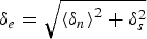 . Then d depends on the effective displacement during the loading process, as shown in the following formula:
 is the effective displacement for complete damage,
 is the effective displacement corresponding to the initial damage,
 is the maximum displacement reached during the loading process. When the energy of the cohesive element reaches the energy Γ dissipated due to failure, the interface unit is completely failed.
RVE model of single-fibre CMCs with lip-shaped matrix cracks
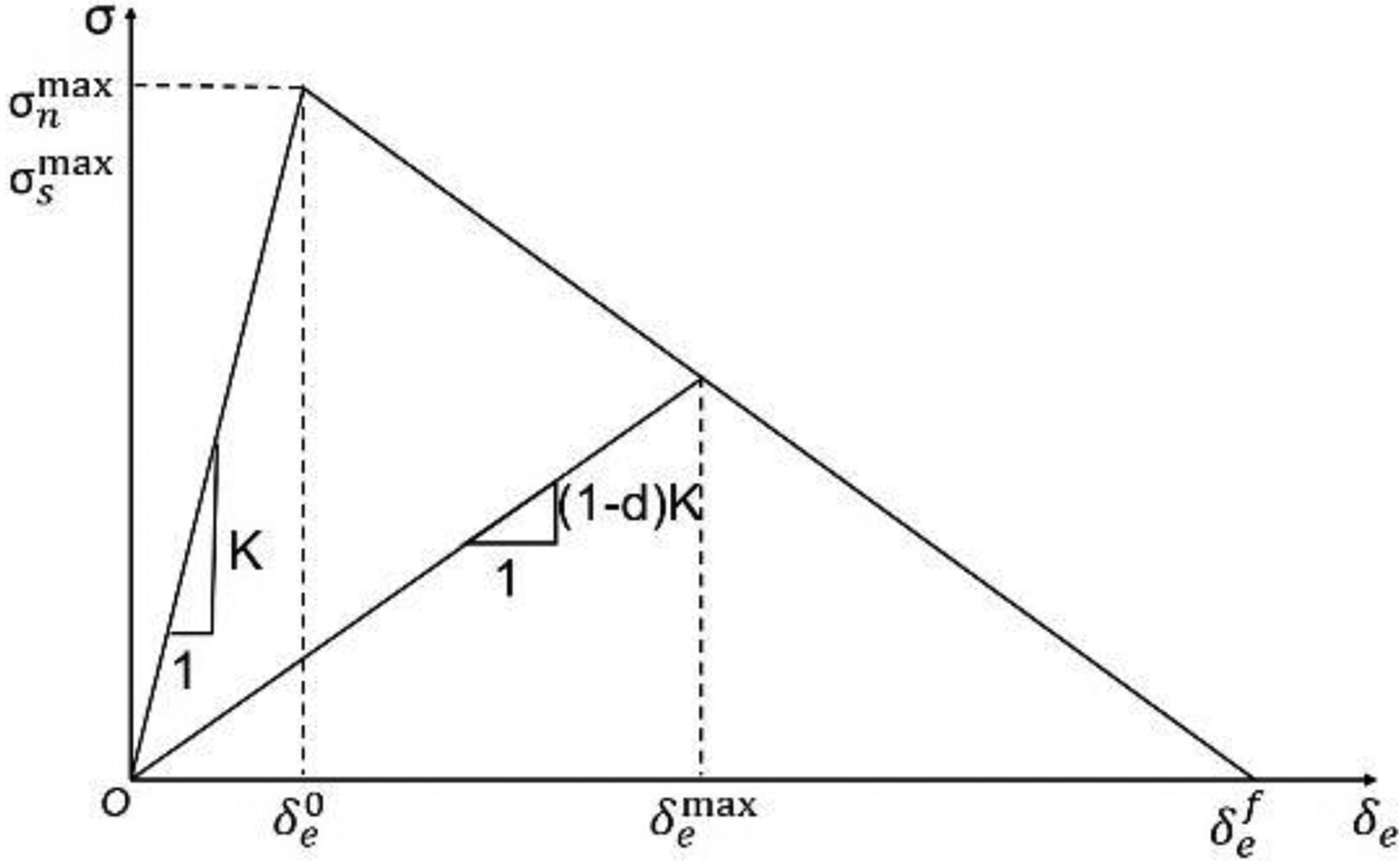
A fibre with a circular cross-section and two half-lip-shaped matrix cracks embedded in a square domain, as shown in Figure 6(a), to analyse the influence of lip-shaped matrix cracks on the failure process of CMCs under transverse tensile. L is the side length of the model, R was the fibre radius, and the fibre volume fraction
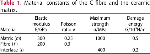
A single fiber model with periodic lip-shaped matrix cracks in the matrix under transverse tension. Material constants of the C fibre and the ceramic matrix. . The whole system was a two-dimensional plane strain problem. The interface was simulated by inserting a zero-thickness cohesion element (COH2D4). The matrix and fibre were both plane strain elements (CPE4R). The matrix, fibre and interface were represented by subscripts m, f and i, respectively. The elastic modulus of the matrix Em was 300 GPa, the Poisson's ratio νm was 0.25, and the maximum fracture energy Gm was 0.5 MPa.mm. The elastic modulus of the fibre Ef was 200 GPa, the Poisson's ratio νf was 0.3, and the maximum fracture energy Gf was 0.2 MPa.mm, as shown in Table 1. During the fracture process of weak interface CFCC, cracks generally did not propagate in the fibres, so the crack propagation area was limited to the matrix and the interface. The lower face (
 ) was constrained in the y direction, and the upper face (
 ) was imposed a uniformly distributed tensile stress load σ∞. The free mesh was used to discretise the model and the mesh on the lip-shaped matrix crack tip and interface were refined, as shown in Figure 6(b).
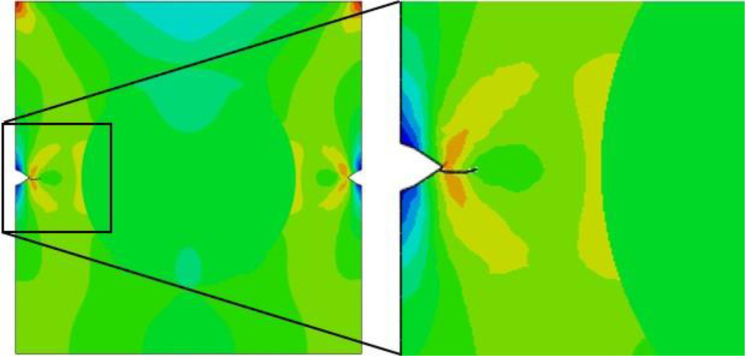
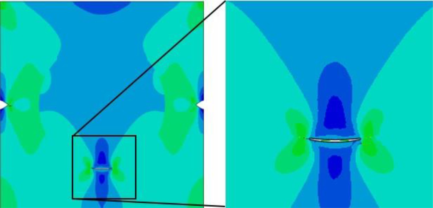
Comparing the radial stress field distribution of the model contained lip-shaped matrix cracks or not, as shown in Figure 7(a) and (b), it can be seen that the existence of lip-shaped matrix cracks changed the radial stress distribution inside the model. For a single-fibre model with an ideal matrix, the maximum stress appeared at the left and right ends of the upper sides of the model, while the maximum stress of the model with lip-shaped matrix cracks appeared at the lip-shaped matrix crack tip. Because the existence of lip-shaped matrix cracks can significantly promote the matrix crack propagation, the initial crack in the model with lip-shaped matrix cracks was possible to not appear at the matrix/fibre interface, but the lip-shaped matrix crack in the matrix will expand first, as shown in Figure 8. It was different from the results of the single-fibre model with an ideal matrix, where the initial crack was created in the matrix/fibre interface [31]. The damage of the interface mainly depended on the interface strength and the interface fracture energy, among which the interface fracture energy determines the debonding ability of the interface [16,18]. Therefore, by remaining the interface strength σi constant, when the interface fracture energy Gi decreases to a certain value, cracks initiated on the interface, as shown in Figure 9. The crack initiation was related to the interface fracture energy Gi. The maximum interface fracture energy was defined as the critical interface fracture energy Gic, under which damage commenced at the interface. When Gi < Gic, the interfacial crack expanded first; when Gi > Gic, the initial crack was created in the matrix along the tip direction of the lip-shaped matrix crack.
Radial stress field for a single fiber model under transverse tension. Initial damage was created in the matrix. Initial damage was created in the interface.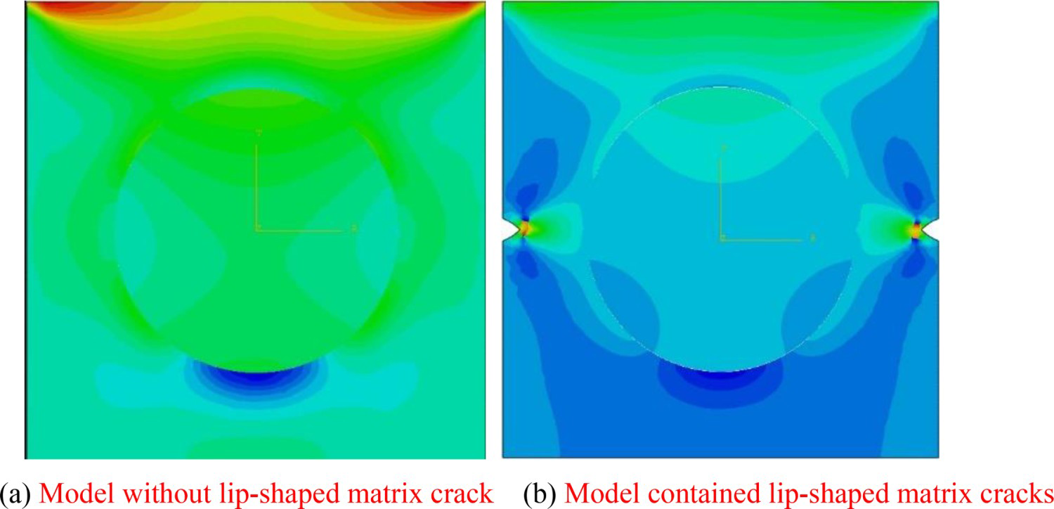
Fracture progress of multiple-fibre CMCs with lip-shaped matrix cracks
Previous studies considered the periodic distribution of fibres and lip-shaped matrix cracks. The random distribution of fibres in CMCs significantly affects the material damage process and macroscopic properties [6]. Therefore, to more accurately predict the failure process of CFCC, it is necessary to establish a multiple-fibre model fully considering the random distribution of fibres and lip-shaped matrix cracks. Based on the actual microstructure of CMCs, the L × L square multiple-fibre model as shown in Figure 10 was established, and the improved random sequential adsorption algorithm was used to generate randomly distributed lip-shaped matrix cracks with different sizes. According to the conclusion given by Carlos González [14], to ensure that the model size does not affect the accuracy of the results, the number of fibres in the model is more than 30, and the distance between the centres of any two fibres is larger than 0.07R to ensure that the discrete areas between the fibres are obtained. The distance between the fibre and the boundary of the RVE model should be larger than 0.1R to avoid the finite element deformation during the meshing process. The model used modified triangles (CPE3 in Abaqus Standard) to automatically discretise the model, which was conducive to the convergence of the results. The remaining parameters and boundary conditions were consistent with the single fibre model in Section 3.
Model Sketch and mesh configuration of the model with 30 fibers.
According to the conclusion in Section 3, if there were no special instructions for the subsequent calculation results, only the case where the interface fracture energy Gi was always smaller than the critical interface fracture energy Gic was considered. In other words, the initial damage commenced from the lip-shaped matrix crack tip.
Crack initiation, propagation and fracture completely
The initial crack commenced from the lip-shaped matrix crack tip as shown in Figure 11(a) and expanded toward the interface closest to the matrix crack tip. The larger the size of the lip-shaped matrix crack, the easier it was to expand first. This was because when the lip-shaped matrix crack had the same width-to-length ratio β, the maximum energy release rate of the larger lip-shaped matrix crack was greater, as shown in Figure 12. Therefore, the larger lip-shaped matrix cracks were more likely to crack first. For lip-shaped matrix cracks of the same geometry (β is constant), the crack initiation depended on the distance l and the angle φ between the lip-shaped matrix crack tip and the fibre centre, as shown in Figure 13.
Failure progress in a multiple-fiber model with lip-shaped matrix cracks (crack density 0.9%, σi = 400 MPa, Gic = 0.2 MPa.mm). Maximum energy release rate of the lip-shaped matrix crack tip with different length a. The distance l and the angle φ between the tip of the lip-shaped matrix crack and the fiber centre.
To investigate the influence of the distance l and the angle φ, the maximum energy release rate of the right crack tip with different distances l and the angle φ was calculated, as presented in Figure 14. The maximum energy release rate of the right crack tip with different angles φ was shown in Figure 14(a). When the angle φ > 60°, the energy release rate of the right crack tip was almost unaffected by the fibre layout, and it was difficult for a lip-shaped matrix crack with a large angle φ to propagate to the interface. Therefore, the results here did not contain the case of φ > 60°. When l/R < 1.5, as the angle φ increased, the energy release rate gradually decreased; when l/R > 1.5, the influence of the fibre on the energy release rate gradually weakened. For the case that l/R = 2, with the increase of the angle φ, the energy release rate increased first and then decreased, attaining a maximum value when φ = 30°. When l/R = 5, the fibre layout almost did not impact the energy release rate, which was almost the same as the result in homogeneous materials. Figure 14(b) showed the maximum energy release rate with different l/R. The greater the distance l, the smaller the maximum energy release rate. Based on the maximum energy release rate criterion, the lip-shaped matrix crack tip was difficult to expand as l increased.
The maximum energy release rate of the lip-shaped matrix crack right tip.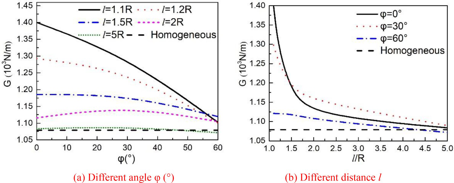
The distance between the lip-shaped matrix crack tip and the fibre centre of actual materials does not generally exceed 1.5 times the fibre radius, that is, l/R ≤ 1.5. Therefore, based on the result of Figure 14, the smaller angle φ resulted in the greater maximum energy release rate. When the angle φ = 0°, the long axis of the lip-shaped matrix crack was located on the centreline of the fibre, and the maximum energy release rate was the largest. In a word, the lip-shaped matrix crack closest to the fibre centre with angle φ = 0° expanded first. Since the lip-shaped matrix crack is symmetrical structure, the same conclusion was also applied to the left tip.
After the damage commenced from the lip-shaped matrix crack, as the lip-shaped matrix cracks expanded, the fibre may experience interface debonding. Usually, the debonding first occurred in the fibres closest to the tip A or Tip B of the lip-shaped matrix crack in a direction approximately perpendicular to the load direction. The interface debonding caused stress concentration in the broader area, which affected the stress distribution of the neighbouring fibres [20]. When there were lip-shaped matrix cracks near the debonded fibres, the matrix cracks became an inducing factor of the direction of interfacial crack's propagation. When the interfacial crack grew to a finite size, the interfacial crack kinked into the matrix, and the kinked direction was towards the lip-shaped matrix crack tip, as shown in Figure 11(b).
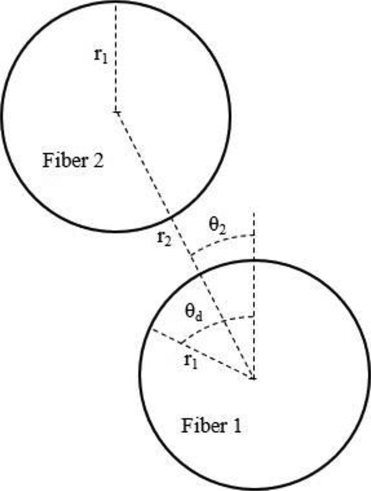
For the broader area around the fibre cluster not contained any lip-shaped matrix cracks, because the initial crack commenced from the lip-shaped matrix crack tip, the stress distribution of the broader matrix and neighbouring fibres was changed, which lead to the area near the initial damage in a direction approximately perpendicular to the load direction more likely to occur further damage, such as the area Zone A in Figure 11(c). In this area, the location of the first interface debonding was highly dependent on the fibre distribution, because the fibre distribution caused the stress concentration. According to the research of C. Sandino et al. [32], the fibre distribution was shown in Figure 16. When 25° ≤ θ2 ≤ 40° and 140° ≤ θ2 ≤ 155°, that is, when the fibre distribution is close to parallel to the load direction, the secondary fibre increases the energy release rate at the interfacial crack tip, making the interfacial crack of the primary fibre easier to expand. The maximum cracking angle θd of the interface crack was defined as the cracking angle upon which the interface crack kinked into the matrix. According to the results of the maximum cracking angle θd under different interface strength and matrix strength was shown in Figure 15, the maximum cracking angle θd of the ideal single-fibre model was about 60–70° [33]. According to the results of C. Sandino et al. [32], when the distance between the centre of the second fibre and the centre of the primary fibre is r2 > 2.5r20, where r20 = 2.416r1 and r1 is the fibre radius, the second fibre cannot affect the interfacial crack propagation of the primary fibre. But when r2 ≤ 2.5r20, for 25° ≤ θ2 ≤ 60°, the maximum cracking angle θd increases; for 70° ≤ θ2 ≤ 80°, the maximum cracking angle θd decreases; for θ2 ≥ 90°, the maximum cracking angle θ
d
is almost the same as the result of the single-fibre model (Figure 16).
The relation between the interface crack angel and interface strength. Model including a primary fiber with interface crack and an undamaged secondary fiber.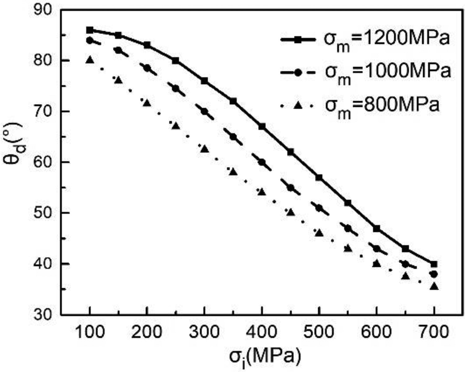
The kinked crack continued to expand towards neighbouring fibres. Owing to the interaction between the fibres, the cracking angle θd of the kinked crack was almost perpendicular to the direction of the load direction, which was the same as the result of Leying Song et al. [15]. Finally, the interface microcracks interacted with the matrix cracks to form a macroscopic crack. The overall deflection direction of the macroscopic crack path was a twisted line transverse the entire model and bypasses the fibre, as shown in Figure 11(c). Different from previous studies that the damage commenced from the interface, the propagation of matrix cracks not only depended on the distribution of fibres but also on the distribution of matrix cracks. The macroscopic crack was found to be in good agreement with these determined by the tensile test [34], as shown in Figure 11(d).
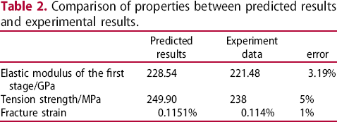
Figure 17 showed the stress–strain curve of CFCC under transverse tension. The predicted stress–strain curve was in good agreement with the experimental results, and there were obvious nonlinear sections. The elastic modulus of the linear segment predicted by the simulation was 228.54 GPa, the predicted tensile strength was 249.951 MPa, and the predicted failure strain was 0.1151%. Compared with the experimental results, these errors between the predicted value and the experimental value were all smaller than or equal to 5%, as shown in Table 2. The above results showed that the model with randomly distributed lip-shaped matrix cracks was suitable for predicting the failure process of CFCC under transverse tensile. However, in the actual CFCC microstructure, the matrix crack distribution was more complex with more randomness, which caused errors in the prediction results.
Stress–strain curve of CFCC with lip-shaped matrix cracks. Comparison of properties between predicted results and experimental results.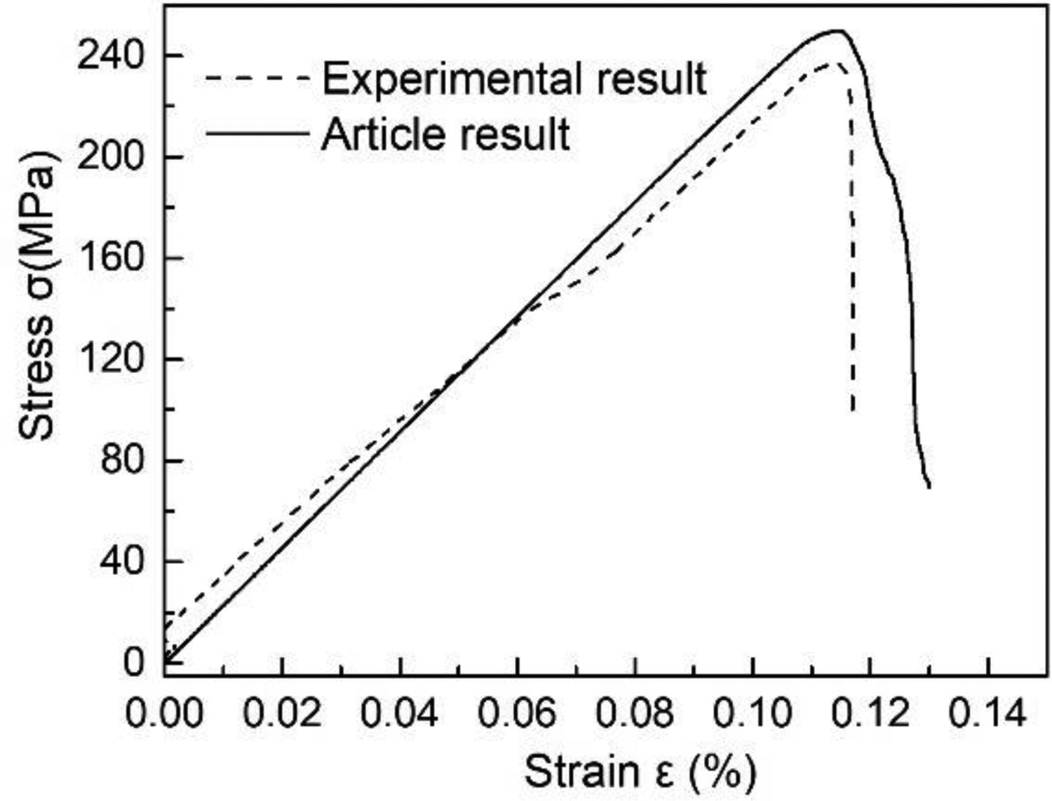
Effect of the lip-shaped matrix crack size
Considering a lip-shaped matrix crack existed in the matrix of the numerical model, this section investigated the effect of the lip-shaped matrix crack size on the failure progress. Figure 18 showed two stress–strain curves of the model with an ideal matrix and the model with a lip-shaped matrix crack which is a = 0.2 mm and β = 0.5. Before the damage commenced in the composite, the existence of the lip-shaped matrix crack lightly reduced the elastic modulus. When the remote load caused the lip-shaped matrix crack to propagate to the closet fibre, the stress–strain curve decreased sharply and then continued to increase linearly. With the remote load increasing, the stress–strain curve exposed an intensive nonlinear characteristic until the composite was damaged completely, undergoing the interface debonding and the kinking path in the matrix. The maximum tensile strength of the model with a lip-shaped matrix crack decreased almost by 20% and the fracture strain decreased by only 0.125%. The existence of the lip-shaped matrix crack eased the failure and seemingly reduced tension properties of CFCC.
Stress–strain curves for the RVE with ideal matrix and the RVE with lip-shaped matrix cracks.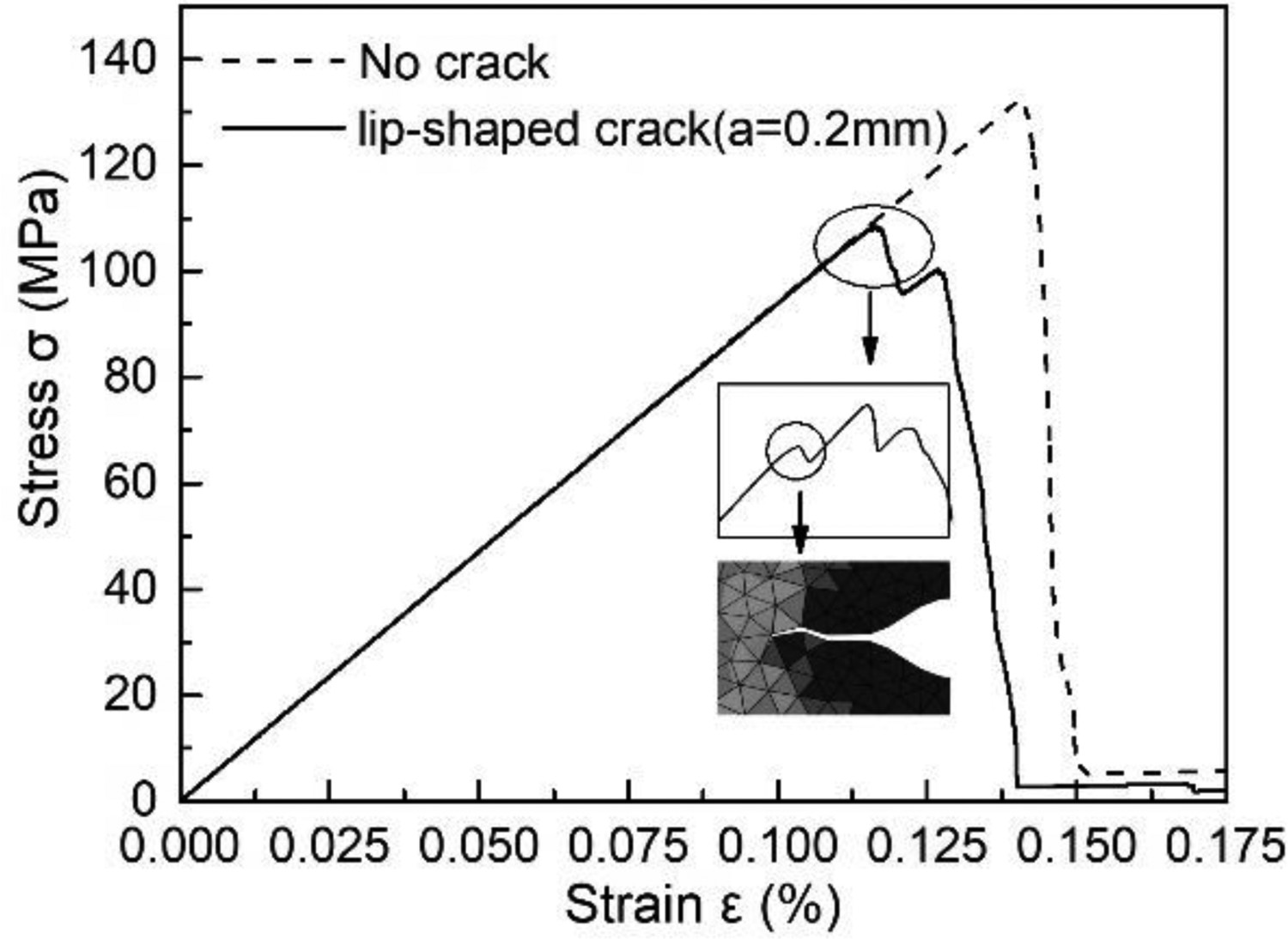
As shown in Figure 19, the different sizes of the lip-shaped matrix crack, i.e. 0.2, 0.3, 0.4 mm, slightly reduced the elastic modulus in the first linear stage but accelerated the generation of the initial crack which was indicated by the dotted line. When the ratio β was constant, the more tremendous stress concentration at the lip-shaped matrix crack tip with the longer half-length, which eased the lip-shaped matrix crack propagation. On the nonlinear stage, due to different crack paths of different models, these stress–strain curves were just analysed qualitatively.
Stress–strain curves for the different size of the lip-shaped matrix cracks.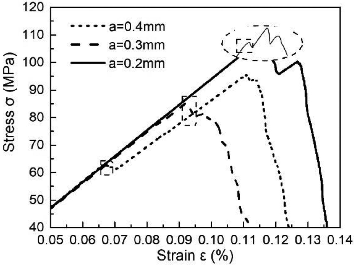
Effect of the lip-shaped matrix crack distribution layout
To exclude the effects of lip-shaped matrix cracks’ position on the stress–strain responses, a fixed layout for the fibre distribution (Figure 10) and 10 different layouts for the random lip-shaped matrix crack distribution (crack density of 2.3%) inside models were created, afterward, the shape and size of the lip-shaped matrix cracks were identical.
It was observed that, on the first linear stage, the elastic modulus of the composite was almost identical as shown in Figure 20. After crack initiation, the nonlinear stage of these stress–strain curves differed obviously. These finial tensile strengths were different in a certain range. To investigate the Measures of Dispersion of results, these tensile strengths and these elastic moduli were collected and analysed statistically, as shown in Figure 21. The average tensile strength is 248.7 MPa with a coefficient of variation of 0.061. The average of the elastic modulus is 218.1 GPa with a coefficient of variation of 0.003. The measures of dispersion of the tensile strength were higher than that of the elastic modulus.
Stress–strain curves for models with different lip-shaped matrix crack distribution layouts. Statistical analysis of material constants.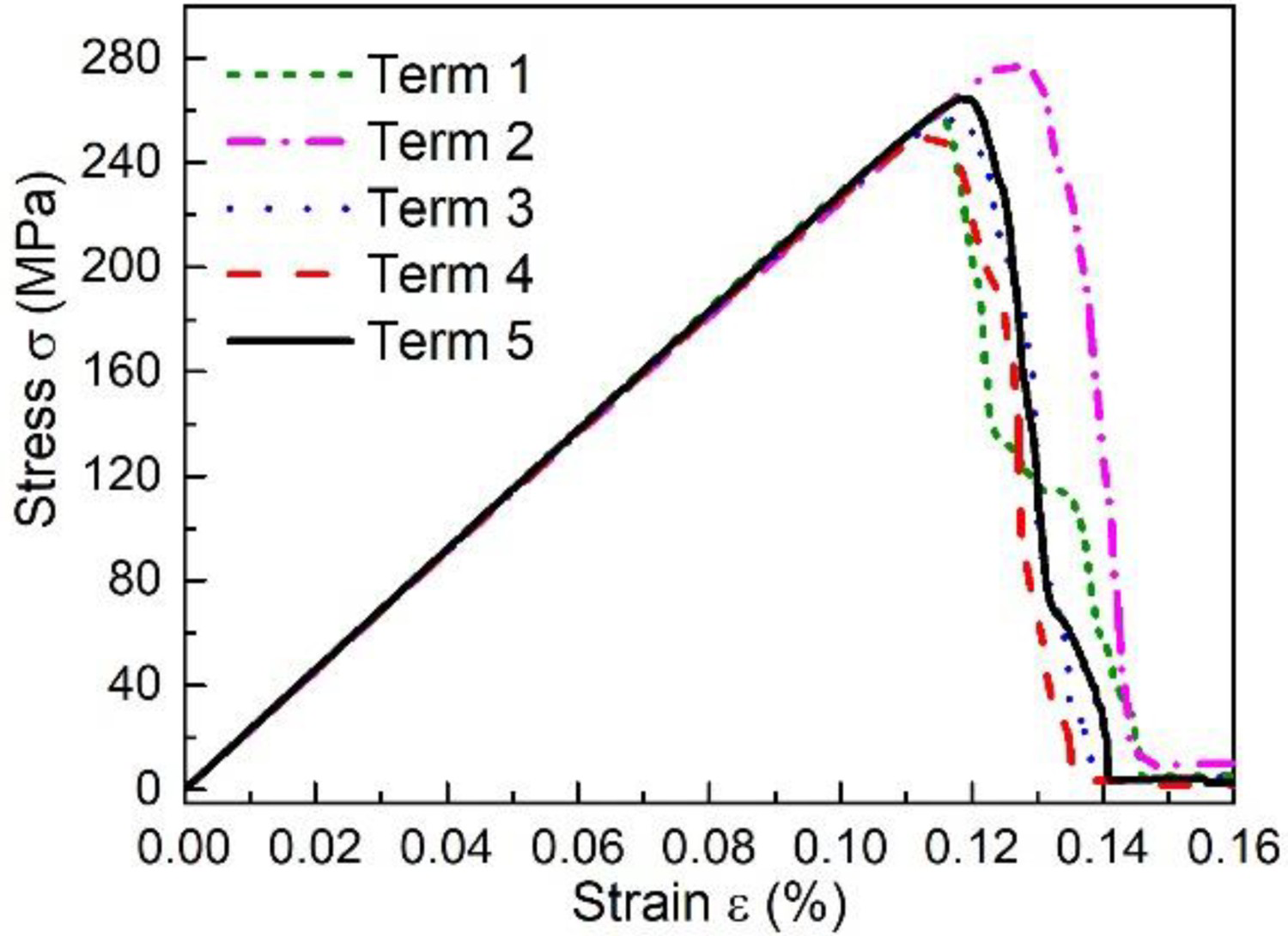
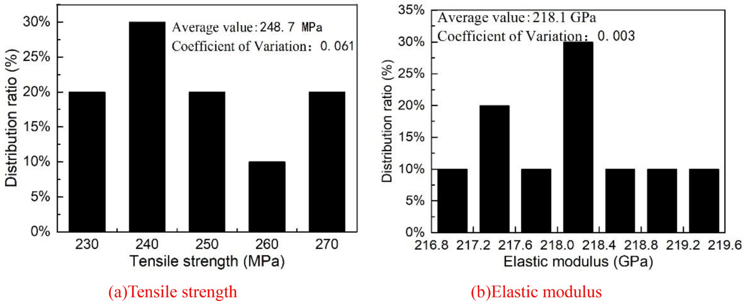
The elastic modulus of the composite depended on the linear response of the stress and the strain, but the tensile strength of the composite was more highly dependent on the distribution of matrix cracks. For models with different lip-shaped matrix crack distribution layouts, macrostructure matrix crack may be created as a dominant crack that crosses the entire RVE dimension or in several regions simultaneously and propagated together.
Although the dispersion of the tensile strength and the elastic modulus, the measures of dispersion of the predicted results were still relatively small. Therefore, the predicted results enabled to be as the accurate values of the CFCC with different microstructures.
Effect of the crack density
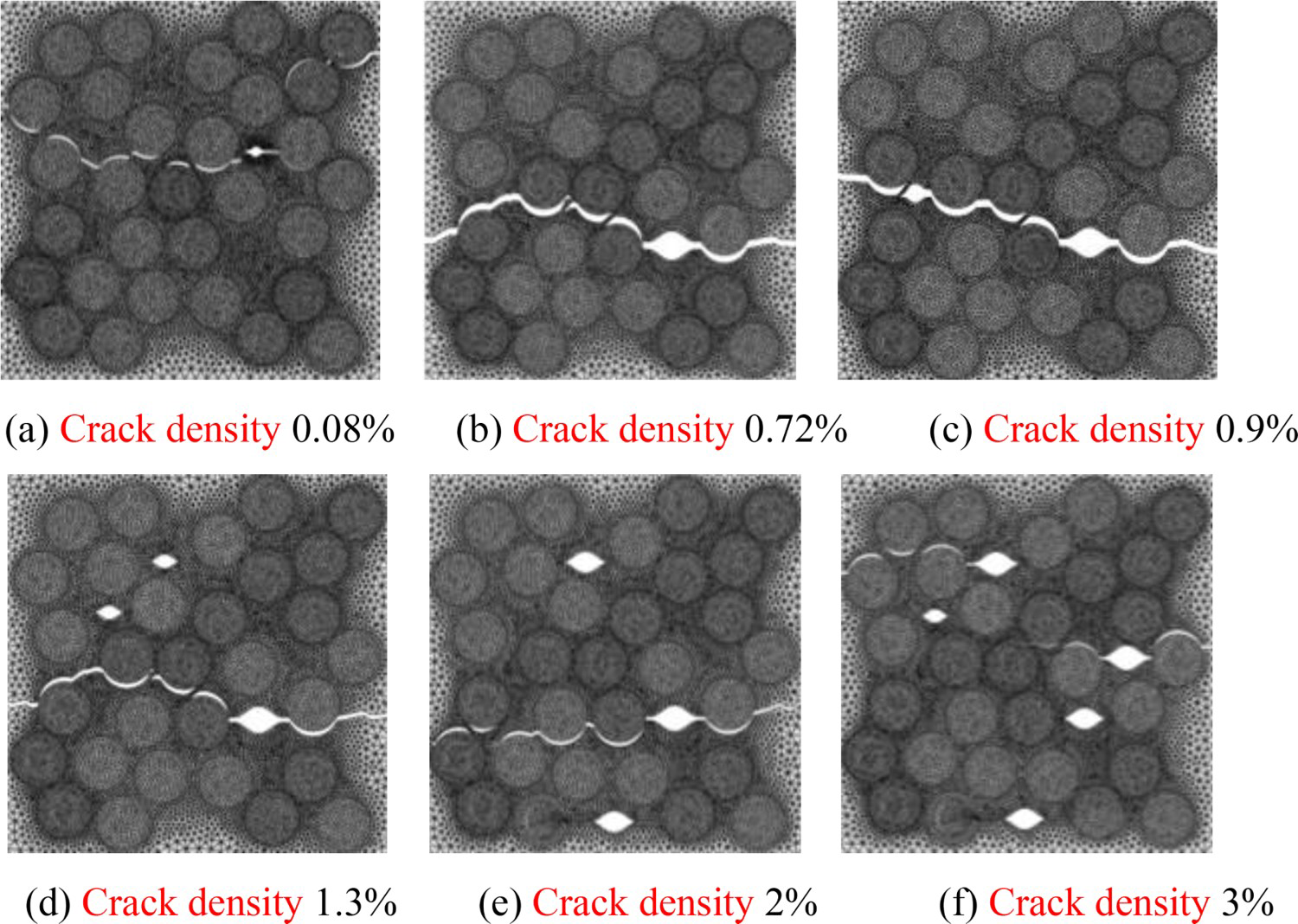
In Section 4.2, the effect of the single lip-shaped matrix crack with different sizes on the failure progress was analysed. To further study the influence of random lip-shaped matrix cracks on the failure progress, six numerical models with six different crack densities (0.08%, 0.72%, 0.9%, 1.3%, 2%, 3%), as shown in Figure 22, were compared. The crack path corresponding to every model (σi = 400 MPa) was shown in Figure 23. In all cases, the macroscopic crack path was different with different matrix crack distributions. However, the initial damage almost occurred at the lip-shaped matrix crack tip, and then one or several fibres experienced interface debonding, forming one or several macroscopic matrix crack paths, which is consistent with the conclusion in Section 4.1. Because of different layouts of lip-shaped matrix cracks in different models, several matrix cracks propagated simultaneously, as shown in Figure 23(f), and the different macroscopic matrix crack paths affected the performance predicted results of CFCC.
Model sketches with different crack densities. Macroscopic matrix crack paths of models with different crack densities(σi = 400 MPa).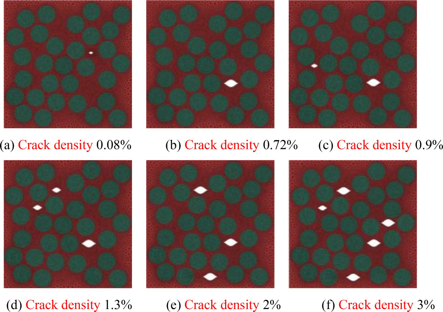
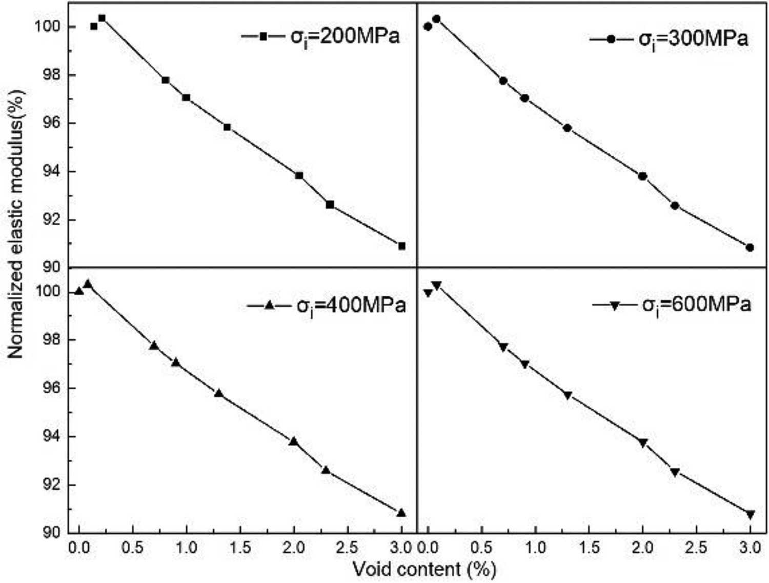
According to the results discussed by P Meyer, et al. [15], different interface strengths resulted in different predicted results. Figure 24 showed the normalised tensile strength with different crack density. It was found that, at the same interface strength, the normalised tensile strength decreased with the crack density increasing. Compared with the model with an ideal matrix, When the crack density was small enough, different crack densities had little effect on the normalised tensile strength. When it closed to 1%, the normalised tensile strength was reduced sharply and then the decrease tended to be stable as shown in Figure 24. The augment of the interface strength intensified the reduction of the normalised tensile strength with identical crack density. This tendency illustrated that the CFCC with higher interface strength should be more sensitive to the existence of the lip-shaped matrix cracks. The difference of the interface strength caused an intensive difference in the normalised tensile strength reduction but had little effect on the elastic modulus reduction as shown in Figure 25. At the same interface strength, the increase by 1% of the crack density almost linearly decreased the elastic modulus by 3%. Combined with Figures 23 and 24, it verified that the CFCC is very sensitive to the existence of the lip-shaped matrix crack inside the matrix, especially with a high crack density and a high interface strength. According to the data, the crack density of CFCC is often very high, and the distribution layout is very complicated. Therefore, improving the robustness of the ceramic matrix composite and reducing the existence of defects in the material can significantly improve the transverse performance of the composite.
Normalised tensile strength with different crack densities (σi = 200, 300, 400, 600 MPa). Normalised elastic modulus with different crack densities(σi = 200, 300, 400, 600 MPa).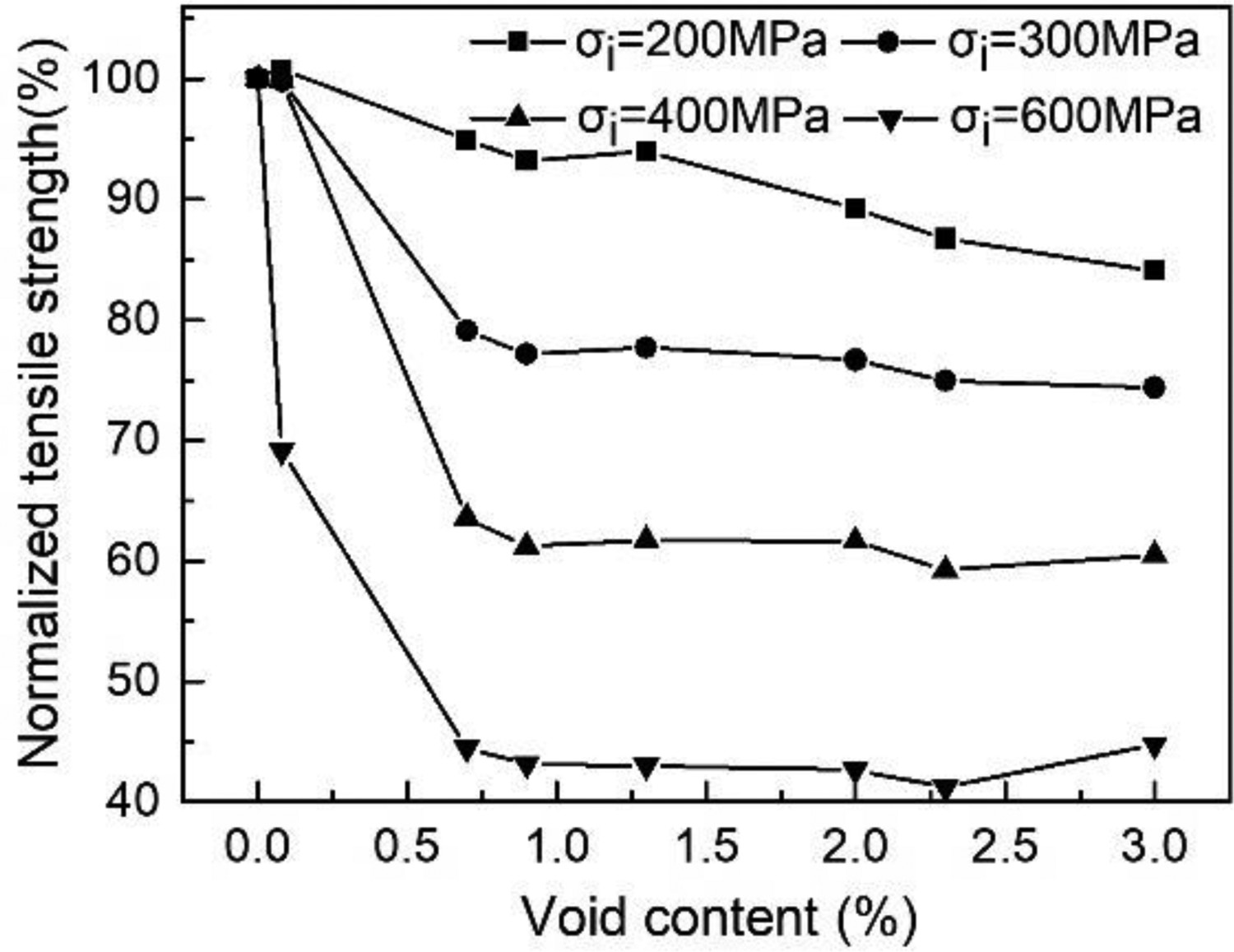
Conclusions
The influence of curved polygonal microcracks in the matrix on the failure process of CFCC under transverse tension was studied. This paper introduced a numerical model that contained random lip-shaped matrix cracks distribution to evaluate the complex failure mechanisms of CFCC under transverse tension. The matrix crack was modeled by the lip-shaped matrix crack. The criterion of the onset of matrix cracking was investigated using the energy release rate criterion and the interface was modeled by incorporating the cohesive surface between matrix and fibre. This study differs from previous microstructure models, of which the matrix is ideal. Considering the matrix contained random lip-shaped matrix cracks distribution, this article has demonstrated that the propagation of matrix cracks not only depends on the distribution of fibres but also on the distribution of matrix cracks. When the interface fracture energy was higher than the critical interface fracture energy, the damage initiation commenced from the lip-shaped matrix crack tip. In the contrast, it was created at the interface. The following conclusion was carried under the case where the interface fracture energy was higher than the critical interface fracture energy. The larger lip-shaped matrix cracks were more likely to expand, accelerating the damage initiation. For lip-shaped matrix cracks with the same geometry, the lip-shaped matrix crack closest to the fibre centre with angle φ=0° expanded first. After the damage initiation, the matrix cracks induced the propagation direction of the interfacial crack. The results regarding the complex failure processes and the material parameters were found to be in good agreement well with experimental results, which verified the numerical model with random lip-shaped matrix cracks distribution enabled to predict the property and the mechanic behaviour of the CFCC under transverse tension.
The different matrix cracks distribution layouts can affect the failure progress of CFCC. Macrostructure matrix crack may be created as a dominant crack that crosses the entire RVE dimension or in several regions simultaneously and propagated together, due to the different matrix cracks distribution layouts. In models with different lip-shaped matrix cracks distribution layouts, the elastic modulus of the CFCC was less discrete, because of the high dependence on the linear stress–strain response. But the tensile strength was more discrete because the tensile strength was high dependence on the macroscopic matrix crack paths. Overly, the predicted tensile strength was variable in a certain range. Finally, at the same interface strength, the normalised tensile strength and normalised elastic modulus both decreased with the crack density increasing. The interface strength affected the tensile strength reduction but almost did not affect the elastic modulus reduction. The stronger the interface, the larger the reduction in the tensile strength.
Future work should focus on the influence of high-temperature and residual stress. This numerical model has potential in areas such as the damage mechanisms of layered CMC and woven CMC under transverse tension.
Footnotes
Disclosure statement
No potential conflict of interest was reported by the author(s).