
Abstract
A three-dimensional progressive failure analysis methodology was developed to predict the strength of double lap bolted joints in [0°/90°/±45°]2s carbon fibre reinforced plastic laminates. An experimental programme was conducted to verify and validate the proposed computational model. Good agreement was obtained between the experimental data and predictive model. A parametric study was conducted for varied clamping torque and friction coefficient values. The well known effect of those variables on the joint strength was captured. Although the in-plane mode of failure of each individual layer around the fastener hole was predicted, X-ray radiographs have shown that delamination failure is particularly dominant around the washer's outer edge. At present, the proposed model does not account for delamination onset and propagation. Future work will involve implementing cohesive zone elements in regions of interest to capture this interlaminar cracking, a work in which the authors are currently engaged in.
Keywords
Introduction
Bolted joints are the primary fastening elements between metal to composite and composite to composite joints in structural applications, such as large transport airplanes, where relatively large loads are to be transferred. Bolted joint assemblies allow regular inspection/maintenance of the structure during the flight lifetime. In addition, they are relatively insensitive to environmental conditions and require little or no surface preparation before assembly. Despite these advantages, they reduce the strength and load carrying capability of structures due to the stress concentrations around the fastener holes, which can be the source of failure initiation and, consequently, the collapse of the composite structure.1–8
Failure of a carbon fibre reinforced plastic (CFRP) composite structure initiates at significantly lower load levels and develops in a progressive manner up to final failure. The strength of the structure is, therefore, not accurately represented by the point at which failure initiates, and a methodology that tracks the failure progression up to final failure is necessary for accurate strength predictions. Progressive failure analysis (PFA) methodology is a widely accepted approach for this need and is used for the analysis of composite bolted joints.9–17 Based on a finite element (FE) modelling and stress analysis, this methodology can predict the initiation and the localised progressive nature of damage, mode of failure and ultimate strength of the joint. It determines the damage initiation by failure criteria and simulates the progression by means of elastic material property degradation rules, which are determined based on the damage type detected.
Three-dimensional (3D) FE modelling is necessary in order to have accurate PFA predictions for composite bolted joints due to the out of plane stress components around the fastener holes.18Typical failure modes of mechanically fastened composite joints are given in Fig. 1.19 Three-dimensional effects are especially important when modelling the bearing type of failure with a lateral constraint, which may have a significant consequence on the strength prediction of the bolted joints.
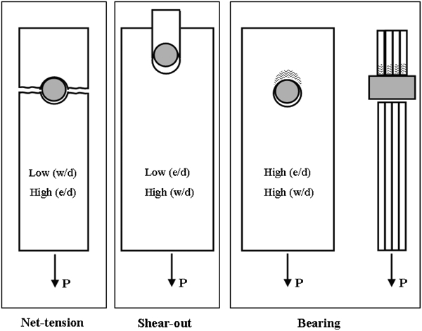
Typical failure modes of CFRP bolted joints
A PFA methodology was developed in the present study to predict the strength of CFRP bolted joints including 3D stress components (σzz, τxz and τyz) at the element Gauss points. An experimental study was also conducted to compare the predicted results. Following the comparison, PFA was performed for varied clamping force and friction coefficients.
Experimental
The [0°/90°/±45°]2s composite laminate was fabricated by hand lay-up technique from commercially available HTS40/977-2 carbon fibre–epoxy preimpregnated (prepreg) tapes in an autoclave according to the manufacturer's recommended curing procedure. The prepreg tapes were made of unidirectional high tensile strength carbon fibres (Toho Tenax, HTS40-12K-800tex) preimpregnated with Cycom 977-2 toughened epoxy resin. The nominal thickness of the laminate was 4 mm. Fastener holes of d = 6 mm were drilled with a backing plate in order to prevent drilling induced delamination failure. The laminates were inspected by X-ray radiography to establish specimen quality.
Double lap loading mechanism was manufactured in accordance with the ASTM standard D5961 as shown in Fig. 2. The washers between composite and steel plates have inner and outer diameters of d = 6 mm and dw = 12 mm respectively, with a thickness of 2 mm. To make sure that the specimen will fail in non-catastrophic bearing mode, e/d = 3 and w/d = 6 ratios were used. The length L of the specimen was 135 mm.
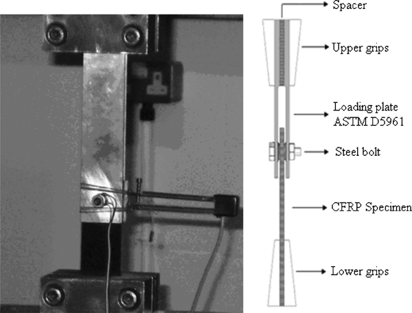
Test set-up (schematic is not to scale)
Tests were conducted at a 1 mm min–1 loading rate with a MAYES testing machine. Applied load, crosshead displacement and bolt displacement were recorded using a computer aided data acquisition system. Three tests were performed in order to obtain an average strength value. Clamping torque was applied by a calibrated torque wrench. Following testing, specimens were inspected by X-ray radiography.
Modelling and analysis
Finite element modelling
Three-dimensional FE modelling and PFA were performed using the commercial software ANSYS v12·1.20 The geometry, boundary and loading conditions used are shown in Fig. 3. To reduce computational cost, symmetry conditions were imposed along the two orthogonal planes (xy–xz) of the model. In the experiments, 50 mm part of the specimen length was clamped between the loading grips, and this part was not modelled. All degrees of freedom were constrained at the fixed end of the laminate to simulate the fully clamped laminate end.
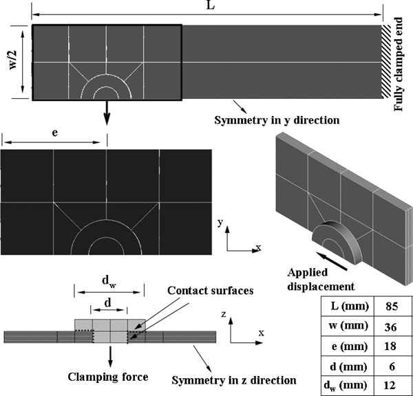
Bolted joint model geometry, boundary and loading conditions
The clamping torque and bolt displacement were applied in sequential load steps. First, a certain amount of displacement through the (negative) z direction was assigned to the bottom of the fastener in order to simulate the initial clamping torque.21 The displacement corresponding to the selected value of the clamping torque was determined by checking the reaction forces of the fastener. Then, an incremental displacement was applied to the bolt along the (negative) x direction in order to load the specimen (see Fig. 3).
Fully integrated eight noded brick elements (SOLID45) were used to model each of the 0·25 mm thick layers, which were discretised with one element per layer in the thickness direction (see Fig. 4 for the detailed laminate and bolt meshes). The element aspect ratio was set to 2·0 at the laminate hole boundary, according to the results of a parametric FE mesh study1 due to the large contact compressive stress gradients and damage, which were expected to occur at this location. The mesh density was reduced away from the hole to reduce solution runtimes, as this area was less critical in the analysis. A maximum aspect ratio of 8·0 was used away from the hole region.
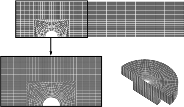
Finite element model meshes of laminate and bolt
Since the clamping force was transferred by means of the washers between the composite laminate and the steel plates (see Fig. 2), only the washer and bolt shank were considered, i.e. the steel plates and bolt head/nut were omitted. The bolt shank and the washer (will be referred to as fastener hereafter) were modelled as a unique steel solid deformable body using SOLID45 linear eight noded brick elements with full integration formulation since it was the most realistic option among others (coupled bolt, spider bolt, etc.).21, 22 The steel properties were E = 210 GPa and ν = 0·3. Surface to surface deformable standard contact algorithms were defined between the fastener (TARGE170) and the CFRP laminate hole boundary (CONTA174), and the fastener (TARGE170) and the CFRP laminate surface (CONTA174)20, 21 (see Fig. 3).
A perfect fit was assumed between the fastener and the laminate, and friction coefficient was assumed to be μ = 0·2 for all contacting surfaces. An augmented Lagrangian contact algorithm was used to check the amount of penetration against the allowable tolerance. It is worth noting that the CONTA174 element is a high order element, and its midnodes were dropped to comply with the eight noded SOLID45 elements of the composite laminate.
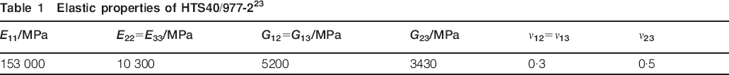
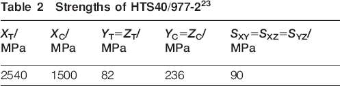
Equivalent orthotropic material properties were assigned to each unidirectional composite layer in order to model the [0°/90°/±45°]2s composite laminate according to predefined local coordinate systems (see Table 1).23 The fibre direction of the 0° layer coincides with the loading direction. Linear elastic material behaviour was assumed for the composite laminate, and material non-linearities were not taken into account (i.e. non-linear shear stress–strain behaviour).12 Strength values of the composite laminate are given in Table 2.23
Elastic properties of HTS40/977-223
Strengths of HTS40/977-223
Progressive failure analysis
A macro-based computer program has been developed in ANSYS to perform the required steps of the PFA.1 Hashin failure criteria24 have been used widely for 3D PFA,14, 16, 25 since it is able to distinguish the distinct failure types of composite materials such as matrix tensile/compressive cracking and fibre tensile/compressive fracture. Owing to the large shear stresses occurring at 45° angle to the loading direction on the compression loaded side of the bolt hole, Hashin fibre tensile criterion can lead to inaccurate predictions.12 The combined Hashin and maximum stress failure criteria (see Table 3) were used in this study, as it was postulated as an effective method to predict the failure behaviour of mechanically fastened composites.12
Mixed mode failure criteria and reduced material properties12
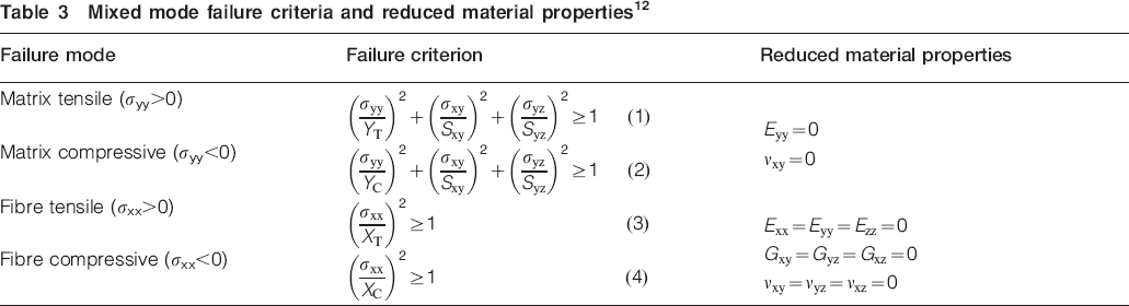
When a failed element was detected, its elastic material properties were reduced by certain degradation factors associated to the respective failure type of the element in order to eliminate its load carrying capability (see Table 3). In one approach, the effect of failure on the elastic properties of an element is simulated using internal state variables (ISVs).9, 10, 14Since the crack surfaces under tensile loading are traction free unlike compressive loading, it was proposed that the ISVs should be determined separately for each different failure mode.9, 10 Despite the realistic physical base, the ISVs should be determined by parametricstudies for each new laminate to be analysed, which is a time consuming and unpractical procedure. Another straightforward approach is to reduce the failed element's corresponding elastic properties to zero, and it was used in the present study. The drawback of this method is that the PFA stops prematurely due to the excessive element distortions. It was shown that the program stops just before the unstable failure growth, and the strength of the joint can be predicted with acceptable accuracy. However, the mode of failure may not be represented accurately.13 In order to overcome the possible numerical instabilities, the material properties were reduced to very small values instead of zero.
The accuracy of the predicted results was strongly 2dependent on the displacement increment, and therefore, the bolt displacement was applied at 0·0125 mm increments.26
Results and discussion
Applied load as a function of the crosshead displacement is given in Fig. 5 for the three CFRP bolted joints tested under 15 N m clamping torque. Failure load of the joints was taken as the maximum load sustained. The average maximum load was 23 024 N with a 3% standard deviation and was used for validation of the PFA prediction.
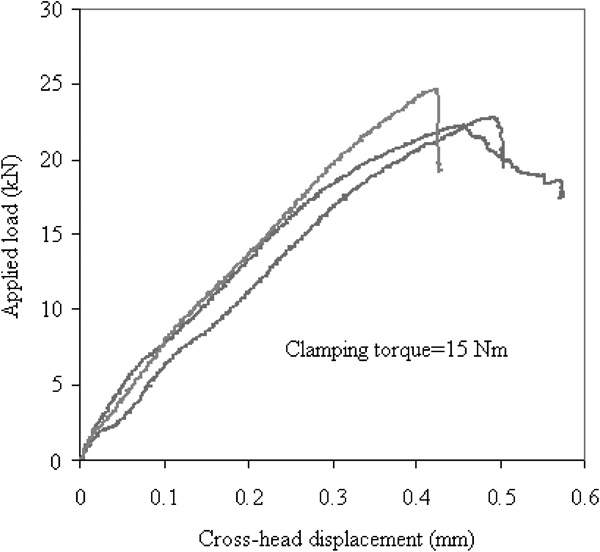
Applied load versus crosshead displacement
The predicted load–bolt displacement curve for 15 N m clamping torque is shown in Fig. 6. Friction coefficient between all the contacting surfaces was assumed to be μ = 0·2. Load values were calculated from the total reaction forces at the fixed end of the laminate for each individual bolt displacement increment. A good agreement between the experimental average maximum load (23 024 N) and the predicted maximum load (21 752·8 N) was obtained.
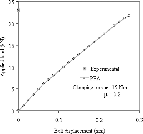
Comparison of experimental result and PFA prediction
Figure 7 shows the effect of different clamping torque values on the strength prediction with the same friction coefficient of μ = 0·2. The influence not only on the maximum load but also on the stiffness predictions is clearly identified.
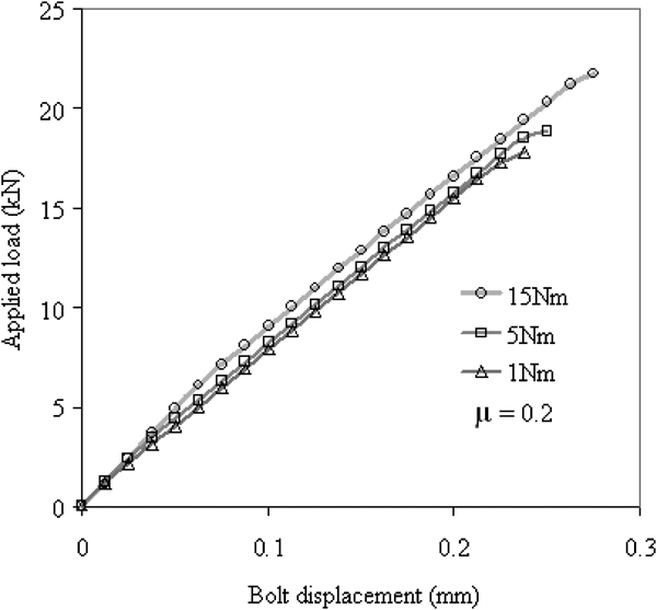
Effect of clamping torque on strength and stiffness prediction
Effect of the friction coefficient is shown in Fig. 8 for a constant 1 N m clamping torque. The maximum load increased with increasing friction coefficient, as expected, due to the increased amount of load transferred by friction.
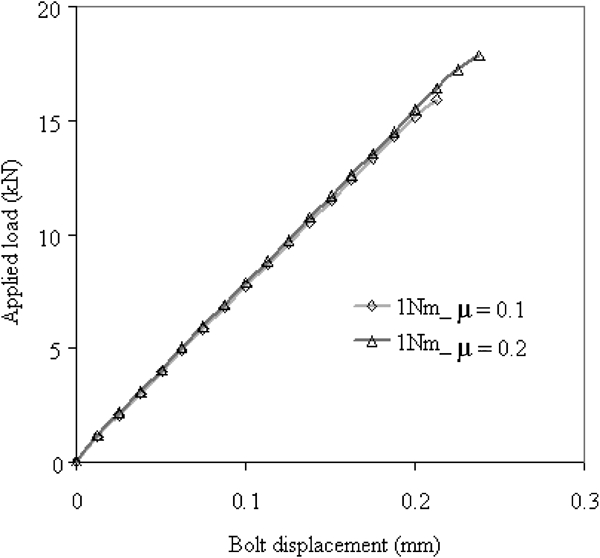
Effect of friction coefficient on strength and stiffness prediction
The effect of clamping torque on the maximum load carrying capacity is already shown in Fig. 7. The clamping torque also has a considerable effect on the failure mode of the bolted joint. Typical failure modes are shown in Fig. 1 for mechanically fastened composite specimens, and a significantly different mode of failure was observed under 15 N m clamping torque as shown in Fig. 9. The failure load of the joint was 22 400 N, which was determined by the maximum load before a significant load drop according to ASTM standard D5961. The bearing mode of failure around the loaded part of the bolt hole is shifted to the outer edge of the washer due to the high clamping forces, which suppress the failure under the washer. Matrix cracks and intralaminar splitting along the ±45° fibres under the washer are also visible from the X-ray radiographs.
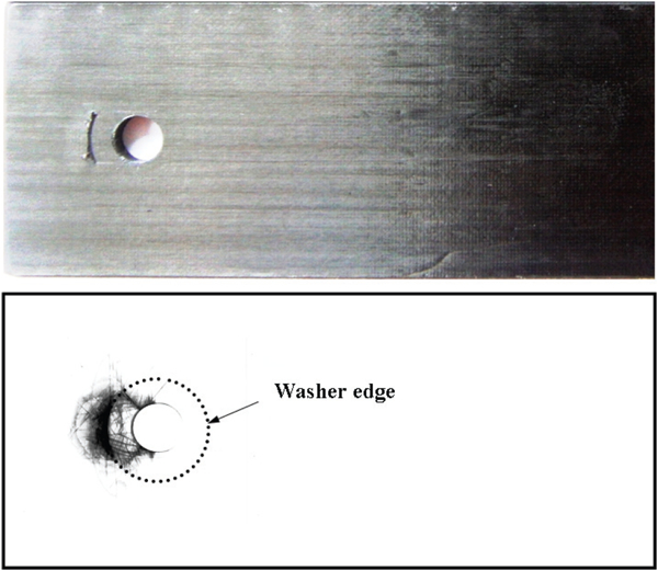
Photograph and X-ray image of CFRP specimen failed at 22 400 N under 15 N m clamping torque
The predicted failure load of the joint is 21 752·8 N, and it was determined when the PFA stops due to the excessive element distortions. Matrix and fibre failure modes predicted by the PFA are shown in Fig. 10 as an example for the first 0° layer of the [0°/90°/±45°]2s laminate. Extensive matrix cracks were predicted at 45° to the loading axis due to the high shear stresses. Fibre fracture was also predicted at and around the loading axis. The current model is not able to predict the delamination failure and the splitting cracks.
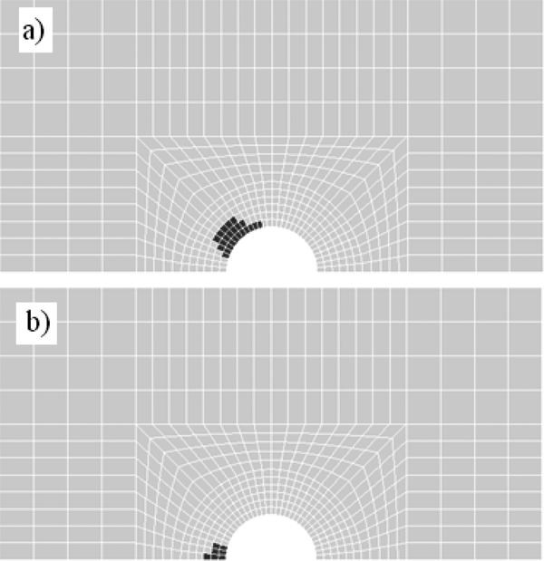
Predicted failure in first 0° layer of [0°/90°/±45°]2s laminate at failure (21 752·8 N)
Conclusions
A 3D double lap bolted joint was modelled, and a PFA methodology was developed to predict the strength of the joint. PFA, in collaboration with FE analysis, simulates damage initiation and growth by means of material property degradation rules, which are related to damage type that occurred throughout the loading process.
Prediction of the 3D PFA is in good agreement with the experimental result. The well known beneficial effect of increasing the clamping torque and friction coefficient on the failure load was also captured effectively. Matrix tensile/compressive cracking and fibre tensile/compressive fracture modes were predicted. In the near future work, cohesive zone elements will be inserted between the adjacent layers in order to capture delamination and its effect on joint strength.
Footnotes
Acknowledgements
The authors wish to acknowledge the Turkish Council of Higher Education (YöK) and Balikesir University for the PhD scholarship awarded to Mr A. Ataş. Cytec Engineered Materials Ltd is acknowledged for the material supply.
This paper is part of a special issue on Deformation and fracture of polymers and their composites