






Abstract
The current study investigates the impact characteristics of polymeric-based nanocomposites strengthened with carbon nanotubes, nanoclay, aluminum oxide and silicon carbide particles nanofillers. Different weight percentages of each nanofiller were prepared. A dead weight drop mechanism was utilized to compare the impact characteristics of different nanocomposite materials. An X-ray technique was utilized to characterize the formation of microstructural defects of the laminated composites post impact. The results showed that the nanoclay fillers were the best to enhance the impact and mechanical properties of the composite materials with 4.3 wt% of nanoclay being the optimum percentage.
Keywords
Introduction
Nanocomposite materials have recently created a revolution in high-performance structures. The widespread use of these composites has attracted the attention of scientists in many engineering applications due to their superior characteristics. The development of such materials enables the circumvention of classic material performance trade-offs by accessing new properties and exploiting unique synergies between materials. This occurs when the length scale of morphology and the fundamental physics associated with a property coincide, i.e., on the nanoscale level. Through control/alteration of the additives at the nanoscale level, one is able to maximize property enhancement of selected polymer systems to meet or exceed the requirements of current military, aerospace and commercial applications. The technical approach involves the incorporation of nanoparticles into selected polymer matrix systems whereby these particles may be surface-treated to provide hydrophobic characteristics. 1
One of the important characteristics of nanocomposites that lead to their wide use in many industrial applications is their improved impact resistance.2–4 These composites are used in a number of engineering applications across various industries, including such products as automobile airbags, flexible structures like boat sails and parachutes, reinforcement in composites, architectural expressions in building roof structures, protective vests for security circles and protective layers around the body in planes.
The main objective of the current study is to investigate the potential use of different types of nanofillers in woven Kevlar laminated composites to enhance their composite impact energy resistance and mechanical properties. Four types of nanofiller particles were used, namely aluminum oxide (Al2O3) carbon nanotubes (CNT), nanoclay (NC) and silicon carbide (SC) particles. 5 It is shown that the variation of nanofiller percentage leads to different mechanical characteristics of the resulting composite, and an increase of the energy absorption by a high percentage of fillers may accompany tendency to delamination. To investigate such effects, different percentages of fillers were utilized in the conducted experiments. Two sets of samples, for each of the fillers used, were prepared with a different fiber/matrix percentage for each composite. The results were compared to control samples composed of Kevlar plies only. Since the weight of the composite is important as a design parameter in such applications needing high strength-to-weight ratio, the effect of fiber/matrix percentage was also investigated.
To achieve the objectives of this research, an in-house-developed vertical drop-weight experimental setup was utilized to test the prepared sample laminates. This setup was built according to the guidelines given in the standard specifications “ASTM- D 7136”. 6 The test procedure determines the damage resistance of multidirectional polymer matrix composite laminated plates subjected to a drop-weight impact event. The potential energy of the drop-weight is specified prior to each test, whereas the damage resistance is quantified in terms of the resulting size and type of damage in the sample. An X-ray technique has also been utilized to characterize the changes in the internal structure of the different Kevlar-laminated composites after impact. Front and side views were taken for each type of Kevlar composites, the X-ray films then were exposed to strong illumination source to reveal the image details, then photos were captured using 10 mega pixels digital camera.
Materials used in preparing samples
The test samples were prepared by incorporating the four used additive particles (Al2O3, NC, CNT, SiC) into selected polymer matrix systems. 1 All four additives were added in two different percentages to the vinylester (VE) to manufacture two different sets of samples.
The NC additive used is of the Montmorillonite clay, Nanomer I.34TCN type, obtained from the Sigma-Aldrich company (Missouri, USA). This NC contains 25–30 wt% methyl dihydroxyethyl hydrogenated tallow ammonium. The multi-walled CNT particles used in this research was obtained from the Nanolab company (Newton, Massachusetts, USA). The diameter of each single CNT was in the range was 10–30 nm and the length in the range 5–20 µm. The Al2O3 particles used are with 50 µm size obtained from FLUKA Company (St Gallen, Switzerland). The SiC particles with 1200 Grit number (15.3 µm particle size) are of the black type and obtained from the PANADYNE Company (Warminster, Pennsylvania, USA).
Samples preparation
Samples description
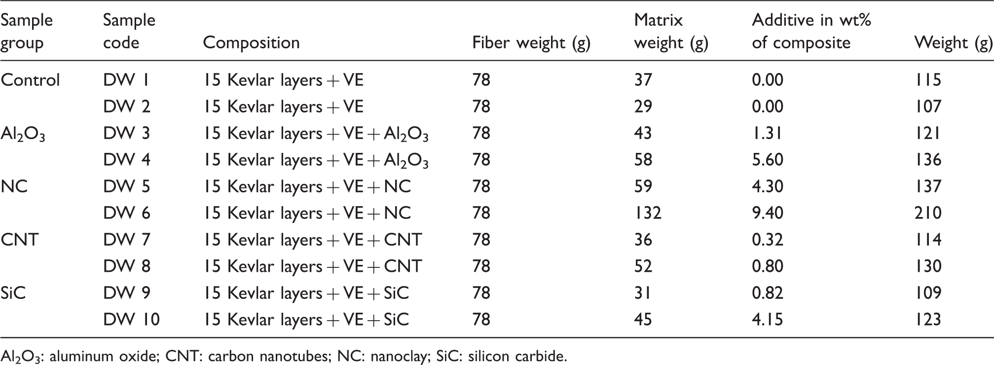
The control samples (170 × 170 mm size and 0.125 mm thickness) were prepared by mounting 15 woven Kevlar 49 layers, provided by Fiber Materials Inc., USA, arranged symmetrically in 0°/45° orientations. The Kevlar plies were bonded together with general-purpose vinyl ester resin (AOC-Resins Co, USA). K-12 hardener with 0.5 wt% was added to insure and accelerate the vinyl ester curing. The percentage of vinylester was determined by the minimum amount of resin required to insure complete saturation of Kevlar layers by resin. The matrix mix was prepared in such a way to insure saturation of each Kevlar layer. The fiber/matrix ratios were calculated after finishing the hot process operation to ensure that these ratios correspond to the composites when used in real applications. It is shown that the resin amount needed to saturate the Kevlar layers was increased by increasing the percentage of fillers. It has been noticed that in spite of the small percentage of an added filler, the change in matrix viscosity due to the filler had a noticeable effect on the composite weight.
Composite samples description.
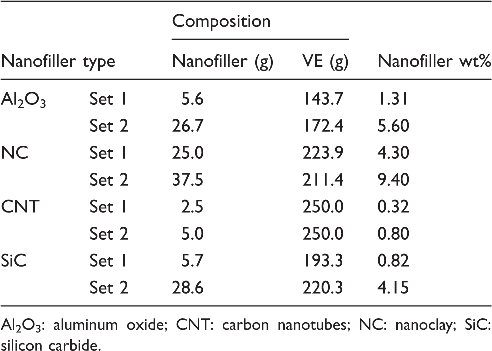
Al2O3: aluminum oxide; CNT: carbon nanotubes; NC: nanoclay; SiC: silicon carbide.
Samples coding
Description of samples.
Al2O3: aluminum oxide; CNT: carbon nanotubes; NC: nanoclay; SiC: silicon carbide.
It can be seen from Table 2 that the resin amount needed to saturate the Kevlar layers was increased by increasing the percentage of additives; this was due to the increase in viscosity of the matrix mix when the additive percentage increased. It should be noted that the change in fiber/matrix percentage in each sample is reflected on each sample weight. The weight of the composite is, thus, important as a design parameter, especially in applications that need high strength-to-weight ratio materials. It can be noticed that the particles reinforced samples demonstrated an increase in weight, as compared to the control sample Group DW 2, varying from 2% in the composite containing 0.82 wt% SiC to 96% in the composite containing 9.4% of NC. Although the additives’ weights were very low as compared to the weight of the Kevlar and resin, the change in matrix viscosity had a considerable effect on the composite weight.
Experimental setup
The impact energy absorption characteristics of the Kevlar composites were investigated using an impact energy test. This test was carried out by utilizing a vertical drop-weight experimental setup with rails to guide the falling weight during the free fall with known height and weight. This setup, shown schematically in Figure 1, was built according to guidelines given in the ASTM-D 7136.
6
The main advantage of such a setup is that it is unidirectional with no preferential direction for failure and can be used to test molded samples. Moreover, the samples do not have to shatter to be considered failures. These factors make falling weight testing a better simulation of functional impact exposures, and therefore closer to real-life conditions.
An experimental setup for drop-weight impact tests. (a) impactor, (b) strain-gauged load cell, (c) rebound catch block, (d) photodiodes, (e) flag, (f) clamping device, (g) locking pin, (h), drop guide, (i) accelerometer.
The developed setup is appropriate to test samples with 50 × 50 mm square dimensions with 1–10 mm thickness. Each tested sample was supported over a hollow steel chamber with an inside dimension of 50 × 50 × 10 mm. The cylindrical steel striker has 25.4 mm (one inch) diameter and 50 mm length and is allowed to fall from a height of up to 1.3 m onto the sample.
The test method adopted here determines the damage resistance of multidirectional polymer matrix composite laminated plates subjected to a drop-weight impact event. A flat, rectangular composite plate is subjected to an out-of-plane, concentrated impact using a drop-weight device with a cylindrical impactor. The potential energy of the drop-weight is specified prior to each test. The damage resistance is quantified in terms of the resulting size and type of damage in the specimen. The damage-resistance properties generated by this test method are highly dependent upon several factors including specimen geometry, layup, impactor geometry, impactor mass, impact force, impact energy and boundary conditions. Thus, the results are generally not scalable to other configurations and are particular to the combination of geometric and physical conditions tested.
The test was conducted in the following sequence. The weight was first lifted manually by the rolling handle to the desired level, the sample was placed between the fixing plates (specimen chamber), then the locking screw was placed to prevent any lateral sliding, after that the weight was released toward the sample. After the impact, the weight was lifted again to release the impacted sample, the locking screw was removed and the sample was liberated. Each test was followed by visual investigation to identify failed samples. The number of removed layers and the delamination between the woven Kevlar layers in the lateral direction was noticed and recorded. Similar procedures were adopted by Hallett and Ruiz 14 to study the response of unidirectional reinforced carbon/epoxy beams consisting of alternate 0°/45° plies under low speed impact.
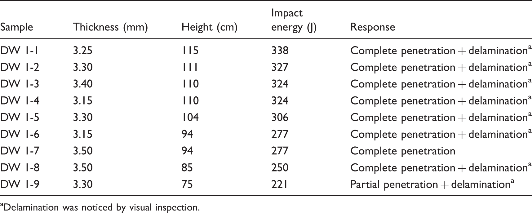
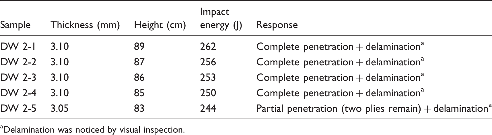
The control samples were used to evaluate the minimum energy required to penetrate the composite specimens. This amount of energy is considered to be a constant parameter during the entire research. The different composition composites were impacted with the same amount of energy. The height was varied and the failure mode was noticed. Complete penetration took place at heights of 850 mm and above. With a load mass of 30 kg, this is equivalent to 250 J potential energy.
Results of the impact test
The main focus was to investigate the impact response of the samples and study their failure modes. Beside the penetration resistance capability, the failure mechanism of all samples are discussed. Since the recorded data are relatively large, the detailed results will be presented here for only two representative sample groups; namely, the Control and Al2O3 groups. However, the results for all tested samples of all groups will be discussed and summarized. The number of samples tested for all sample groups (except DW 1) was five. It should be noted that the two control sample groups (DW 1 and DW 2) were tested under different impact energies to predict the minimum energy required to penetrate the samples. That minimum energy level was determined as 250 J and was then fixed for the rest of the samples with nanofillers.
Control samples – no reinforcement
Impact test results of the control sample group (DW 1).
Delamination was noticed by visual inspection.
Impact test results of the control Samples (DW 2).
Delamination was noticed by visual inspection.
Al2O3-reinforced samples
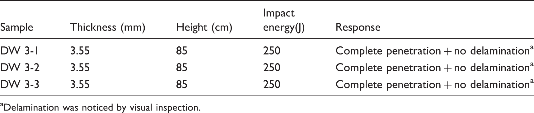
Impact test results of the aluminum oxide (1.31 wt%) samples (DW 3).
Delamination was noticed by visual inspection.
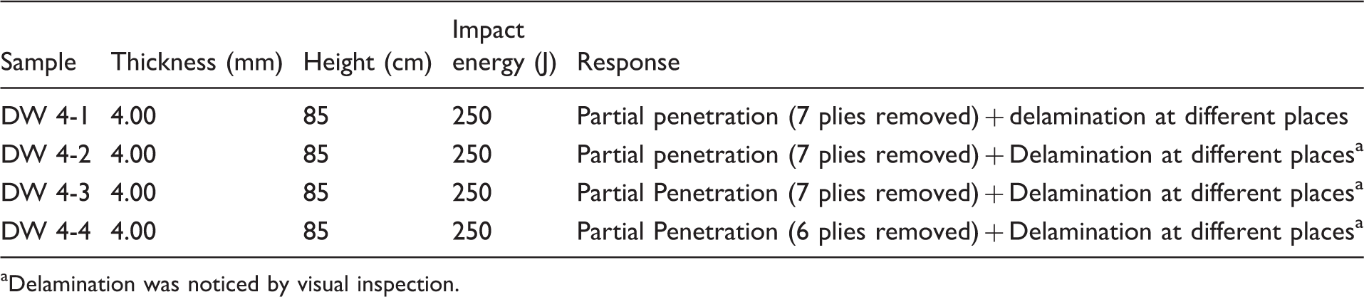
Impact test results of the aluminum oxide (5.60 wt%) samples (DW 4).
Delamination was noticed by visual inspection.
NC reinforced samples
The first set of the NC group (DW 5) contained 4.30 wt% of NC. This percentage was enough to increase the penetration resistance of the composite and the impactor was able to partially penetrate the composite samples in all trials. The visual inspection of the impacted samples did not show any evidence of delamination. The second set of this group of samples (DW 6) contained 9.40 wt% of NC. This high percentage enhanced the impact resistance of the samples in a noticeable way. In fact, the impactor was not able to penetrate the composite samples in all four trials. The visual inspections of the impacted samples showed high tendency of the samples to delaminate and showed almost complete delamination in some samples.
CNTs-reinforced samples
The first set of the CNT group (DW 7) contained 0.32 wt% of CNT. This low percentage was not able to increase the penetration resistance of the composite and, as a result, the impactor was able to penetrate the composite samples in all three trials. However, the visual inspection of the impacted samples did not show any evidence of presence of any delamination. The second set of samples of this group (DW 8) contained a percentage of 0.80 wt% of CNT, which enhanced the impact resistance of the samples in an insufficient way. But the impactor was still able to penetrate the composite samples in the four trials. The visual inspection of the impacted samples did not show evidence of presence of any delamination.
SC reinforced samples
The first set of this group (DW 9) contained a low percentage of 0.82 wt% of SiC, which was not able to increase the penetration resistance of the composite. As a result, the impactor was able to penetrate the composite samples in the three statistical trials. The visual inspection of the impacted samples did not show any evidence of presence of any delamination. The second set of samples (DW 10) contained a high percentage of 4.15 wt% of SiC, which enhanced the impact resistance of the samples in a noticeable way and the impactor was able to partially penetrate the composite samples in the four statistical trials. The visual inspection of the impacted samples did not show evidence of presence of any delamination.
Summary of the impact test results
The low speed impact test results of the four group of samples with different additive reinforcement in addition to the results of the second set of the Control group are summarized in Figure 2. This figure clearly demonstrates that the Al2O3 composites with 1.31 wt% did not enhance the Kevlar composite resistance, but it did change the failure mode by enhancing the lateral direction resistance since no delamination was noticed by visual inspection. Samples containing 5.6% of Al2O3 increased the impact resistance of the Kevlar composite to the extent that the impactor could not completely penetrate the Kevlar layers, but this was at the expense of the delamination resistance achieved by the low percentage of the Al2O3.
Penetration response of Kevlar composite with different additives under low speed impact.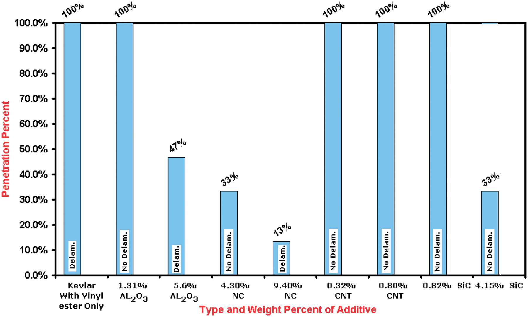
Figure 2 also shows that the NC-reinforced composite samples were the best additive as regarding the impact resistance. Samples with 4.3 wt% were able to relatively resist the impactor where only 5 out of 15 layers were removed with no delamination noticed, while samples with 9.4 wt% of NC resisted the impactor in such a way that only 2 layers were removed. This great response of energy absorption, however, was at the expense of the delamination resistance shown in the composites that contain 4.3% of NC.
CNT-reinforced composites were not able to resist the impactor penetration. This could be due to the random distribution and the low percentage of the CNT used. Although the SiC composites with 0.82 wt% were not able to enhance the Kevlar composite resistance, it changed the failure mode by enhancing the lateral direction. Therefore, no delamination was noticed by visual inspection. Samples with 4.15% of SC increased the impact resistance of the Kevlar composite so that the impactor could not penetrate more than one third of the Kevlar layers and at the same time no delamination was noticed by visual inspection.
X-ray results
An X-ray technique has been utilized to characterize the changes in the internal structure of the different Kevlar laminated composites after impact. Photos of the front and side views were taken for each of the control sample group DW 2 and the other four groups with additive reinforcement DW 3–DW 10. The X-ray films then were exposed to strong illumination source to reveal the image details, then photos were captured using 10 mega pixels digital camera.
As an illustration, the photos of the X-ray results are shown, for only the control group DW 2 and the two sets of samples of the Al2O3 group, in Figures 3, 4 and 5, respectively. The X-ray results of the samples of all groups are summarized, however, Figure 6 shows the delaminated percentage of composite areas. The photos in Figures 4–6 show variation in the light intensity which is due to the delaminated areas. The ability of X-ray to penetrate empty places (delaminated) is higher than its ability in solid regions (non-delaminated). The bright areas represent the delaminated areas while the dark areas represent the remained bonded areas. One can notice considerable match between the front and side view for each sample. Image-processing software was used to modify the contrast and brightness of each photo. This allowed easy prediction of the border line around the delaminated areas.
X-ray results for impacted control sample (DW-2). The sample density is 13.76 g/cm3. X-ray results for impacted composite contains 1.3 wt% of Al2O3 (DW-3). The sample density is 13.6 g/cm3. X-ray results for impacted composite contains 5.6 wt% of Al2O3 (DW-4). The sample density is 13.71 g/cm3. Percentage of delaminated area of each composite (from X-ray images).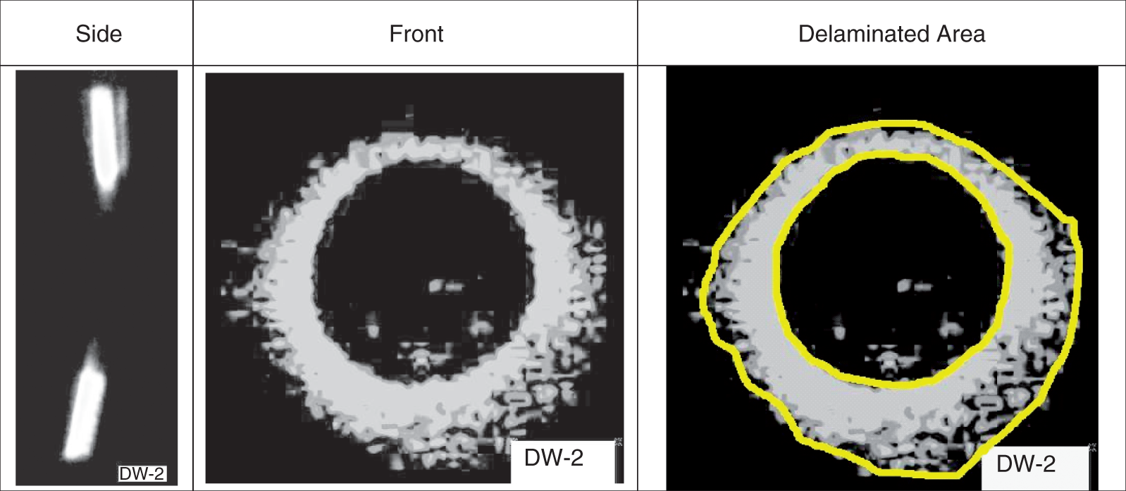
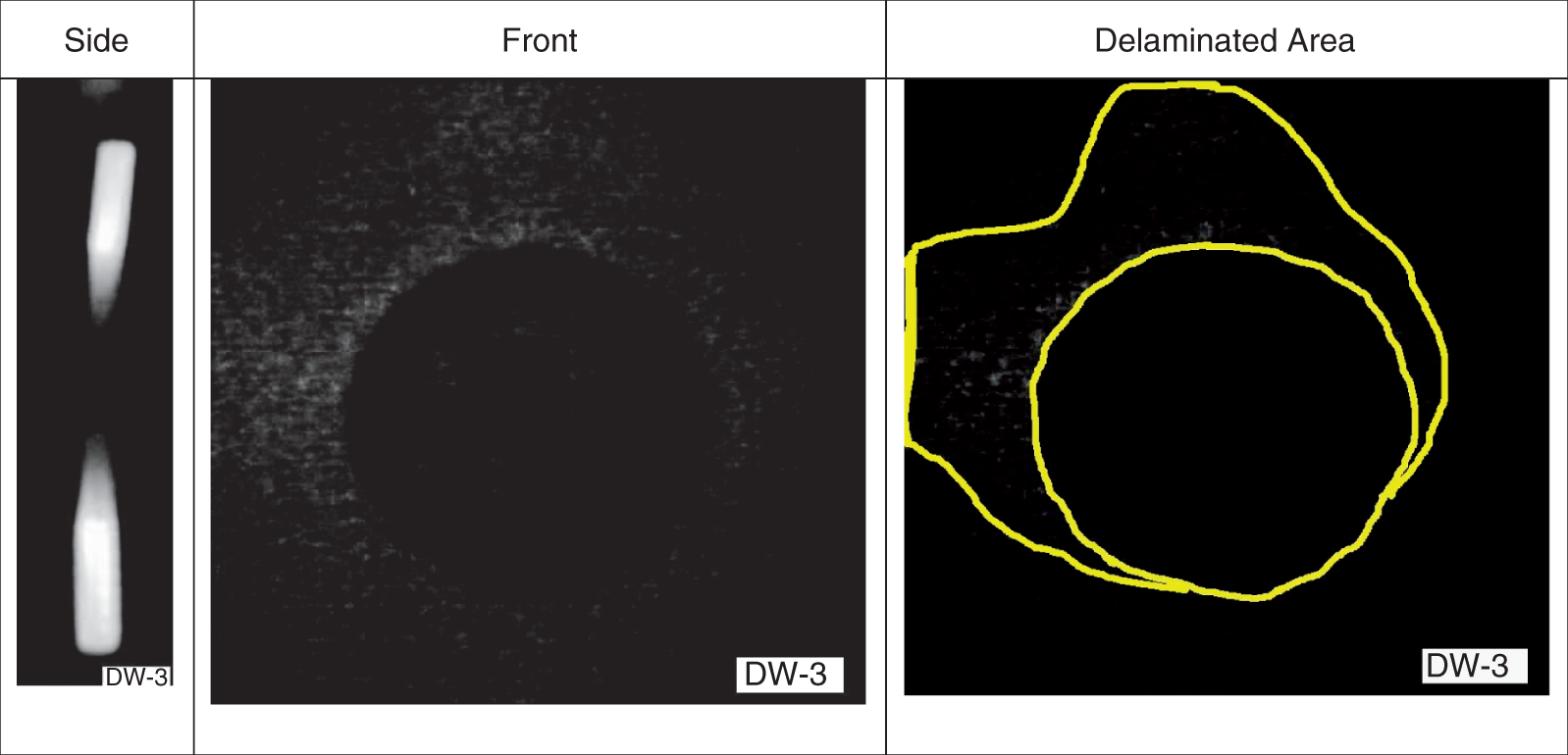
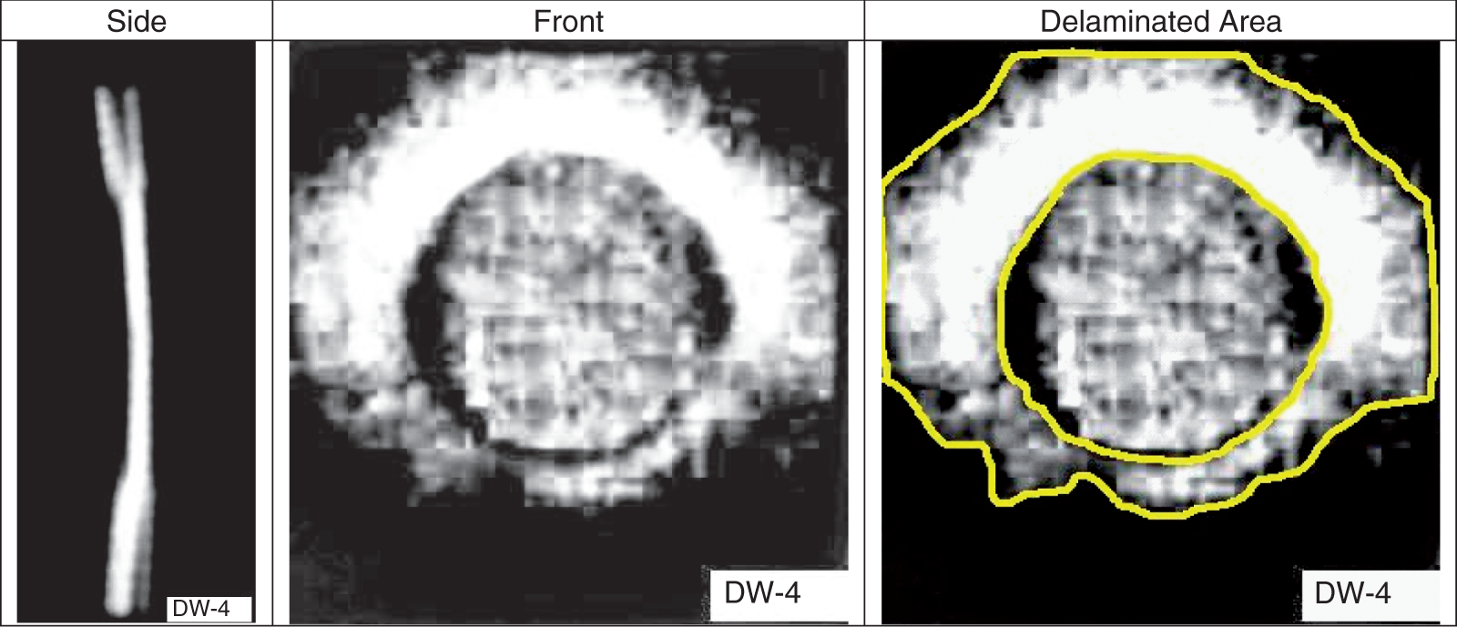
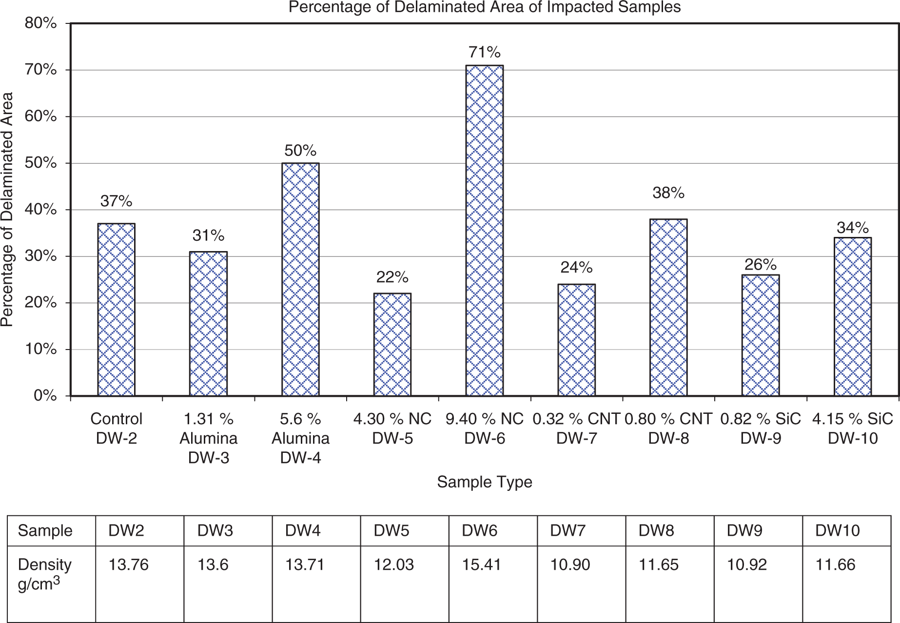
Figure 6 demonstrates that the control samples show high tendency to delaminate where 37% of the sample area was delaminated. The delamination of the control sample started at the circular impacted disk circumference and extended to one of the sample corners. Reinforcement with 1.3 wt% of Al2O3 did not show any evidence of delamination by visual inspection. However, the X-ray results show a decrease in the delaminated area to 31%, while enhancement with a high percentage of Al2O3 (5.6 wt%) increased the delaminated area to 50% of the total area. NC with 4.3 wt% played an effective rule in delamination resistance where it can be seen that the delaminated area reduced to 22%. The increase in NC percentage to 9.4 wt% produced a contrary effect on the results and almost complete delamination happened. The X-ray results showed that 71% of the total area was deboned. Multi-walled CNT with 0.32 wt% decreased the delaminated area to 24% while 0.8 wt% did not change the delaminated percentage neither delaminated places in the control sample. SC particles with 0.82 wt% enhanced the delamination resistance to 26% instead of 37% in the control sample, while 4.15 wt% from the same material resulted 34% delamination percentage. The results of this section revealed enhancement in delamination resistance in all additives at low percentages of additives, while the high percentage aggravated the delamination in all types of additives. The NC with a low percentage (4.3 wt%) had shown the best results in delamination resistance.
Conclusions
The effect of adding small amounts of various fillers on the impact resistance of Kevlar/VE composites has been studied in this work. The research identified methods to optimize the impact resistance of polymeric composites reinforced with laminated woven Kevlar layers. It was demonstrated that the amount of the additive reinforcements exerts significant influence over the energy absorption capability of polymer-based composites. The factors contributing to the enhancement of the energy absorption and failure modes of composites, such as the type of additive and its amount, were investigated. The effect of four different additive particles, namely Al2O3, NC, Multiwall CNTs, and SC, was investigated. Two set of samples with low and high concentration for each additive were prepared and tested. The results were compared to control samples composed of Kevlar plies only. A vertical drop-weight experimental setup was utilized to test the prepared sample laminates.
An X-ray imaging method has also been utilized to characterize the changes in the internal structure of the different Kevlar-laminated composites after impact. Front and side views were taken for each type of Kevlar composites, the X-ray films then were exposed to strong illumination source to reveal the image details. The results revealed enhancement in the delamination resistance at low percentages of NC additives, while the high percentage of NC aggravated the composite delamination. It has been concluded that the NC fillers were the best to enhance the impact and mechanical properties of the composite materials, with 4.3 wt% of NC being the optimum percentage. Among the obtained experimental data, the NC with a low percentage (4.3 wt%) had also shown the best results in delamination resistance. The composite material forms used in this research are limited to continuous-fiber reinforced polymer matrix composites. The properties generated by the low speed impact test method are highly dependent upon several factors, which include specimen geometry, layup, impactor geometry, impactor mass, impact force, impact energy and boundary conditions. Thus, the results are generally not scalable to other configurations, and are particular to the combination of geometric and physical conditions tested.
Footnotes
Acknowledgment
This research received partial funding from the United Arab Emirates University.
Conflict of interest
None declared.
Funding
This research received no specific grant from any funding agency in the public, commercial, or not-for-profit sectors.