






Abstract
An exploratory work has been carried out in the field of three-phase composites in which fly ash nanoparticles were incorporated in addition with 2D and 3D glass woven fabrics while preparing composites. These fly ash nanoparticles were prepared by high-energy ball milling technique and its effect on functional properties of composites were observed. In thermo-mechanical analysis, the composites with the 3D woven fabrics as reinforcement showed higher storage modulus. Further improvement in the storage modulus due to addition of fly ash can be explained as the nanoscale dimension of fly ash nanoparticles have got very large surface area which leads to interaction sites and hence efficient load transfer between reinforcing agent and matrix. Though the addition of fly ash nanoparticles improved the mechanical properties of composites marginally, a significant improvement was observed in functional properties of composites.
Introduction
Woven fabrics in 2D sheet form have many properties, such as drapability, flexibility and comfort, and all of these make them suitable to be used as materials for clothing and other domestic end-uses. 1 However, in case of composite applications, the main cause behind the failure is delamination failure of 2D woven laminates whose interface strength is determined by the bond strength between the matrix and multiple layers of fabrics. Also importantly, crimp in the 2D fabric as composite reinforcement significantly reduces in-plane stiffness and strength of composite. 2 These drawbacks of 2D fabrics as reinforcement material for composite demands a better integral structure with substantial thickness, possibly crimpless and having better strength in through-the-thickness direction. Thus, in its initial part, the research has been focused to investigate the thermo-mechanical properties of 3D woven fabrics of various structures in comparison with 2D fabrics.3,4
The nanostructure offers outstanding attributes as reinforcement to improve the functional performance of composite materials. The high surface areas of the nanoparticles enhance the organic–inorganic interaction. 5 Nanocomposites are expected to exhibit improved electrical, thermal and magnetic properties. They are increasingly used in aerospace, automotive, naval and other industries. The gap in the research of 3D woven composites embedded with nanoparticles has given the opportunity to carry out the research work further. By keeping in mind this wide scope, further exploratory work has been carried out to study the thermal, electrical and electromagnetic characteristics of the 2D and 3D woven nanocomposites.
Materials and methods
Glass fabrics
The main purpose of preparation of glass fabrics was to use it as reinforcement component in composite preparation. To study the effect of fabric structure on composite properties total four different glass fabrics were prepared. The approximate equal areal density of three different 3D woven fabrics is maintained to isolate the effect of fibre content. While preparing 2D plain woven sample warp and weft density is adjusted such that a 3-layered composite will be approximately equal to 3D woven fabrics in terms of areal density.
Specifications for 2D glass fabric
The fibre used is multifilament glass tow with fineness 600 tex. Warps/m is 500 and wefts/m is 300. Areal density is 485 g/m2.
Specifications for 3D glass fabrics
Different structures of 3D woven fabrics e.g. orthogonal, angle interlock and warp interlock were developed with following specifications. Stuffer warps/m is 500, binder warps/m is 300 and wefts/m is 900. Areal density is 1350–1420 g/m2. The weaves are represented in Figure 1. B1, B2 stand for binder warps and S1, S2, S3 stand for stuffer warps.
3D woven fabrics: (a) orthogonal, (b) angle interlock and (c) warp interlock.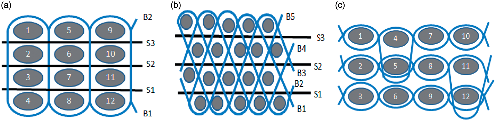
The CCI sample weaving machine was considered to be the best suitable loom for this purpose. Some modifications in the conventional loom made it possible to weave 3D fabric with existing loom. A separate negative let-off arrangement was made behind the loom to hold binder beam while preparing 3D woven fabrics. All three solid woven structures viz. orthogonal, angle interlock and warp interlock as well as 2D plain woven fabrics were prepared on the same machine. The beams required to feed this loom were prepared on the CCI sample warping machine.
Preparation of composite samples
Compression moulding
All composites were prepared by compression moulding technique. LY556 Epoxy resin was used as a matrix component for all the fabrics. The principal advantage of compression moulding is its ability to produce parts of complex geometry in short period of time. SANTECH compression moulding equipment is used to prepare composites. The parameters set on the machine while preparing composites are curing time 900 sec., breathing pressure 6 N/m2, curing pressure 12 bar N/m2, curing temperature 120℃.
Specifications of regular composite samples
Specifications of composite samples.

Preparation of nanocomposites
Preparation of nano fly-ash
The fly ash used in the study was collected from source in Plzeň, Czech Republic. Mechanical activation of fly ash was carried out using a high-energy planetary ball mill of Fritsch Pulverisette 7 in a sintered corundum container of 80 mL capacity using zirconia balls of 3-mm diameter under wet condition in distilled water for 1, 2, 3, 4 and 5 h. The ball mill was loaded with ball to powder weight ratio of 10:1. The rotation speed of the planet carrier was 850 r/min.6,7 In this mechanical treatment, powder particles are subjected to a severe plastic deformation due to the repetitive compressive loads arising from the impacts between the balls and the powder. The nano milling is shown in Figure 2. The milled sample powder was taken out at a regular interval of every 1 h of milling to test for particle size distribution on Malvern Zetasizer Nano based on dynamic light scattering principle. The dispersion medium was deionized water. The dispersion was ultrasonicated for 5 min with Bandelin ultrasonic probe before characterisation.
Schematic of ball milling technique.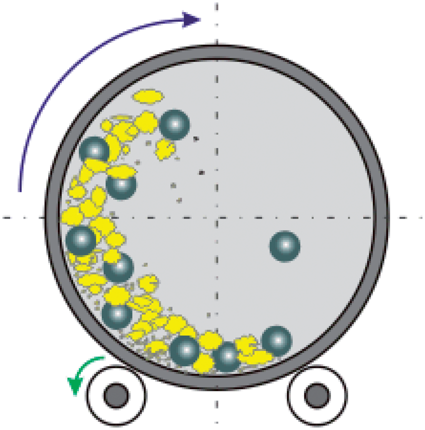
Dough preparation
The fly ash nanoparticles prepared by wet milling process are dried first in the oven at 120℃ for 6 h. Then the amount of epoxy needed was calculated by considering fabric-to-epoxy weight ratio as 60:40; 10% of fly ash was taken on weight of the matrix (epoxy + hardner). This calculated amount of nanoparticles were carefully weighted and dispersed in the hardener first with the help of sonicator. This nanoparticles dispersed hardener was then added to the beaker already containing premeasured amount of epoxy with gentle stirring to avoid formation of air bubbles.
Fabrication of nanocomposites
All the nanocomposites were prepared by the same method as regular composites.
Thermal post-curing
To cure these composites, the fabric layup along with Teflon sheets was sandwiched between a pair of steel plates. These samples were cured at 120℃ for 30 min in mechanical convection oven with predetermined weight on it to maintain uniform pressure.
Test methods
Knife penetration test
To carry out this test, the testomeric tester M350-10CT was used. This is a machine with an adjustable speed of the penetrating knife and a changeable type of stabbing knife. For the testing purposes of this experiment, a single sharp pointed knife, as shown in Figure 3, was used. Each composite sample was placed on the plate of the machine. The machine head is dropped onto the sample thus holding the sample in place. The knife was then allowed to penetrate the sample at a velocity of 1000 mm/min. A recording monitor is connected to this machine and records the maximum force exerted on penetrating the sample. The same test was done on the composites reinforced with fly ash nanoparticles.8,9
Schematic of knife penetration test.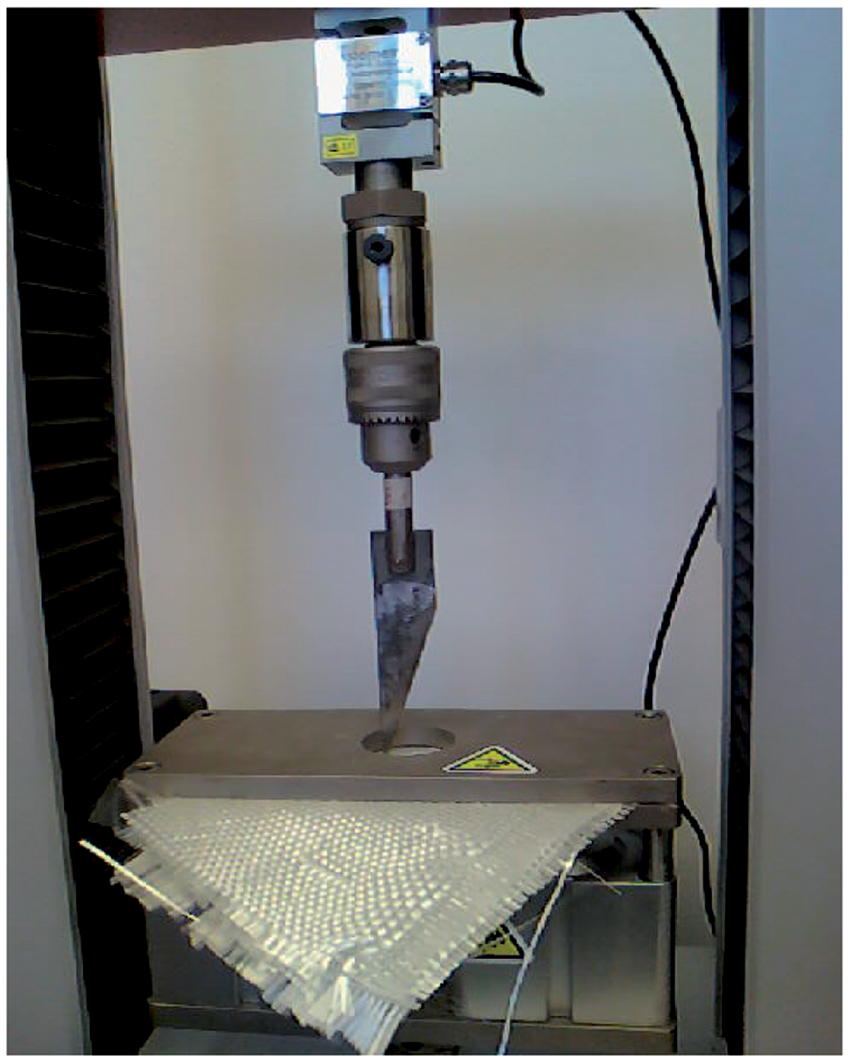
Thermo-mechanical characterization – DMA test
The dynamic mechanical analysis (DMA) of the composite materials was performed on DMA DX04T RMI instrument. The test was performed in three-point bending mode with gauge length and sample width of 30 mm and 10 mm, respectively. The samples were subjected to an oscillating frequency of 1 Hz and 100% oscillating amplitude in the temperature range 30℃ to 300℃ at the heating rate of 5℃ min−1.10,11
Characterization of electrical properties
Hewlett Packard (hp) 4339B high-resistance meter was used to measure the surface resistance and volume resistance of the composites. The environmental condition for the measurement was 22℃ temperature and 29.5% relative humidity and voltage used was 100 V.
Electromagnetic shielding
Electromagnetic shielding was characterized by the attenuation of electromagnetic field power density by using a simple device illustrated in Figure 4. The waveguide principle is used to measure the EM shielding of the material.
Apparatus for measuring electromagnetic shielding.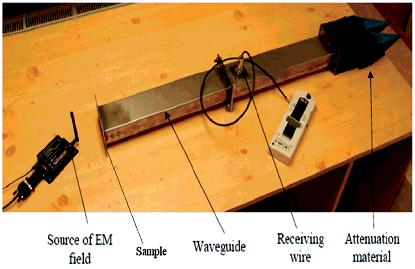
There are two waveguides used in this instrument. One waveguide is connected with receiving wire (antenna). The end of this waveguide is filled by carbon saturated foam which absorbs the electromagnetic field passed through sample. The specimen to be tested is placed on the entrance of second waveguide in such a manner that it is oriented perpendicular to the electromagnetic waves. Transmitting antenna is placed in front of this waveguide input. The source of electromagnetic waves is ZigBee module working at 2.4 GHz frequency.
Results and discussion
Properties of fly ash
Quantitative elemental analysis
Quantitative elemental analysis of fly ash.

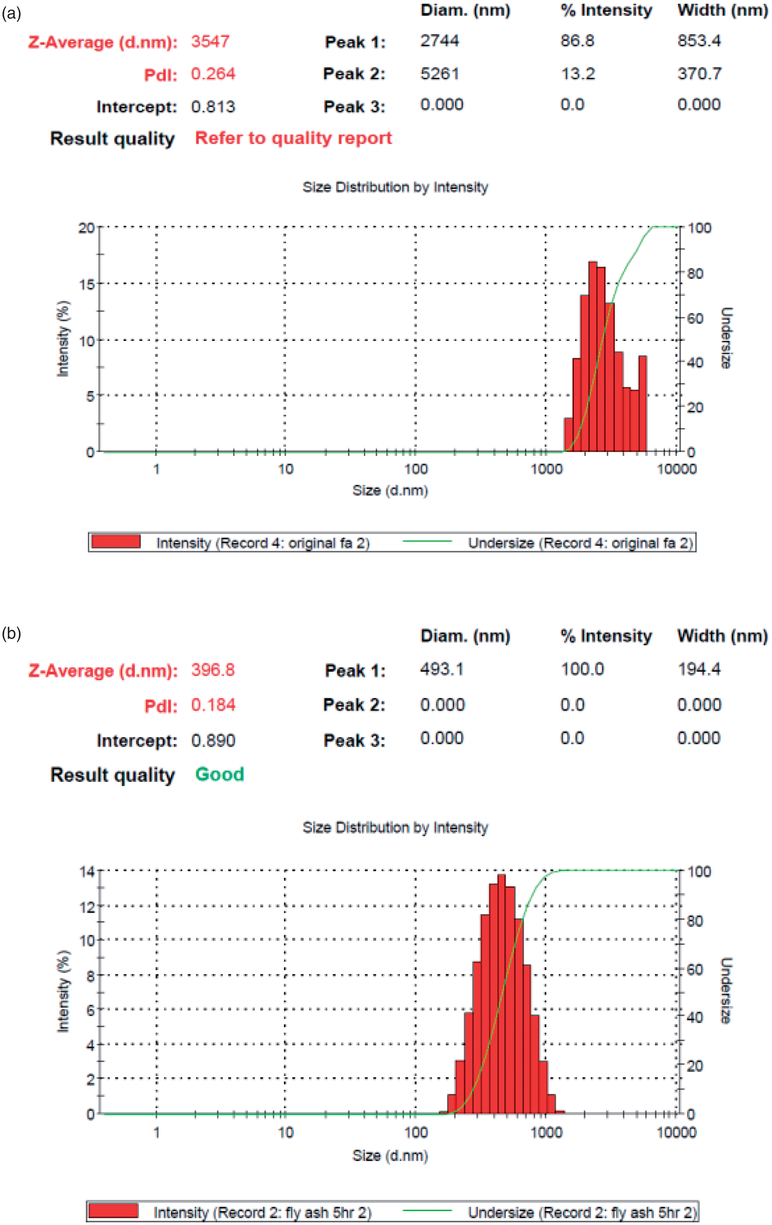
The variation in particle size of fly ash with milling time is depicted in Figure 5. The average particle size of the fly ash procured was 3547 nm. Ball milling of fresh fly ash up to 5 h reduced its size by a magnitude of 10 times to 396 nm. The reduction of particle size after regular interval can be seen from Figure 6. The particle size distribution before milling and after milling for 5 h is plotted in graphs as shown in Figure 6 (a) and (b), respectively.
Particle size distribution after regular intervals of milling. (a) Particle size distribution before milling. (b) Particle size distribution after milling.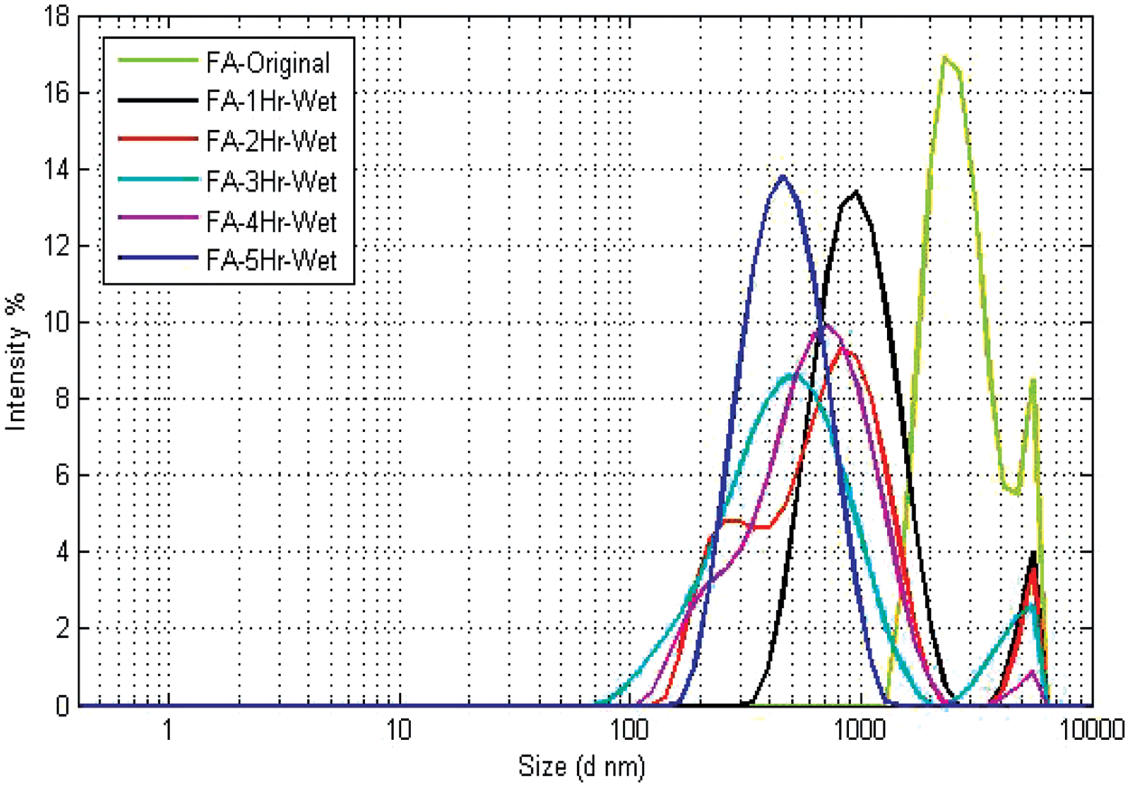
Characterization of composites
SEM of resin nanocomposite
The scanning electron microscope (SEM) fractographs of the nanocomposites are depicted in Figure 7(a) and (b) at two different resolutions, it can be found that the dispersion of fly ash particulates in the matrix for the composite is uniform and the fly ash particulates disperse easily in the matrix. This means that the fly ash particulates could distribute uniformly in the matrix due to their high dispersibility.
Scanning electron microscope (SEM) fractographs of the nanocomposites.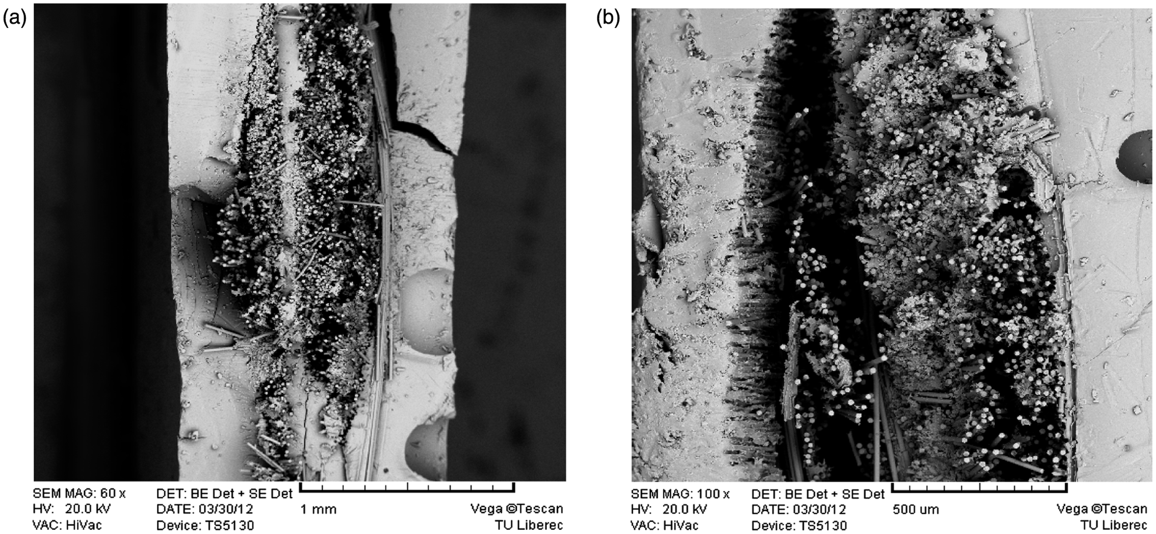
Knife penetration test
The breakdown strength and the work at breaking load are shown in Figures 8 and 9, respectively. 3D woven fabric-reinforced composite shows higher breaking load as compared to the 2D plain woven composite. The 3D orthogonal fabric shows lowest resistance, which may be because of less number of interlacement points in the structure giving chance to easily propagate the crack between the parallel threads when knife penetrates in the composite. The higher deformation of the plain woven composite while penetration of knife results into higher energy absorption and the case is similar for 3D warp interlock woven composite also.
Breakdown strength of composites and nanocomposites. Energy at break of composites and nanocomposites.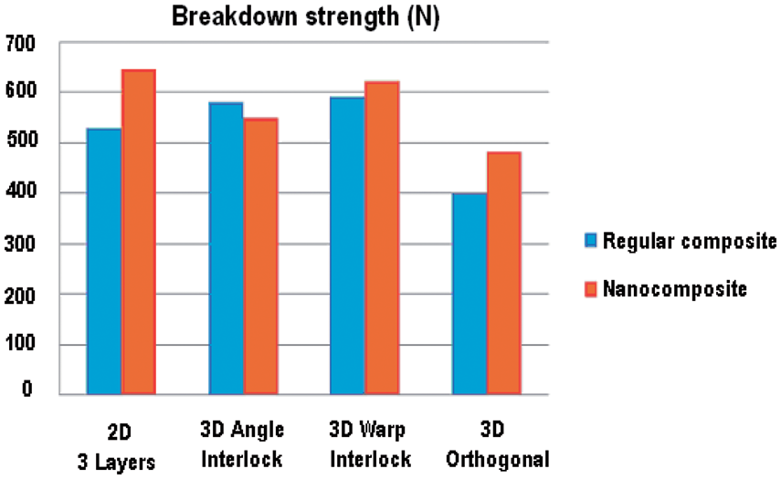
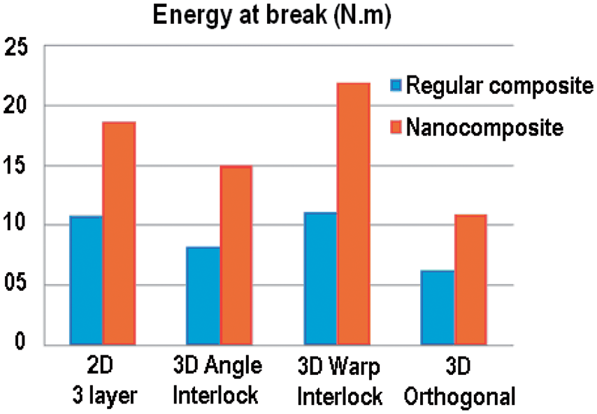
The effect of fly ash nanoparticles can be observed. The addition of nanoparticles improved the breakdown strength and energy by 30–40%. The uniform distribution of the nanoparticles on the surface as well as between the layers of plain woven fabrics while preparing the composites gave the highest change in the breaking strength.
Thermo-mechanical properties (DMA test)
Effect of fabric structure on thermo-mechanical behaviour of composites
Thermo-mechanical behaviour of the epoxy-based composites with different reinforcement structures for regular composites and different loadings of nano fly-ash in case of nanocomposites has been investigated in this study. The effect of different reinforcement structure can be seen from Figure 10. The composites with the 3D woven fabrics as reinforcement show higher values of storage modulus. When compared with the three layers plain woven fabric composite, 14% increase in storage modulus of angle interlock fabric and 26% improvement in the orthogonal and warp interlock fabric reinforced composites is observed. The integral structure of the 3D orthogonal fabric with uncrimped yarns absorbs higher amount of energy.
Storage modulus of composites with different reinforcement structures.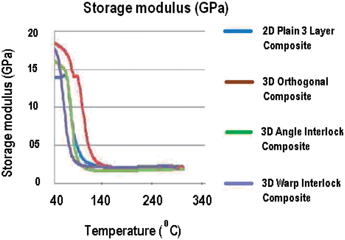
The curves of the temperature dependence of Tan δ in case of regular composites shown in Figure 11 give peaks at 68℃, which is closely related to the Tg of the matrix.
Tan δ for composites with different reinforcement structures.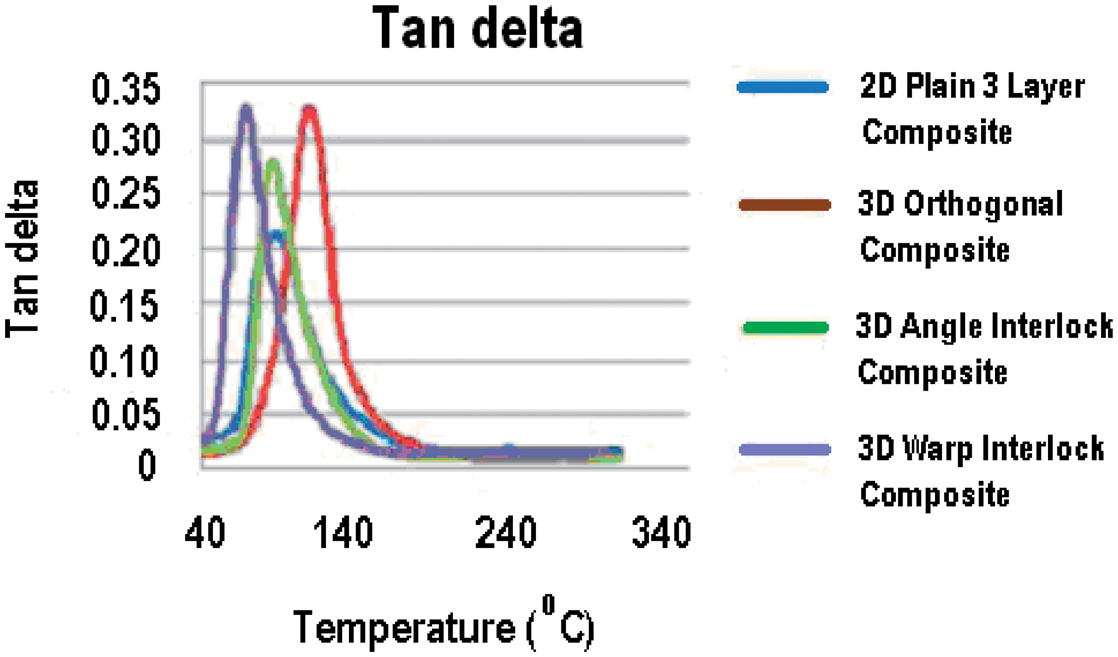
Effect of nanoparticles on the thermo-mechanical behaviour of composites
Figure 12 shows the effect of nanoparticles loading on thermo-mechanical behaviour of the composites. In all these graphs, storage modulus is higher at initial low temparature upto 50–60℃ which indicate glassy region in the composite. This could be an indication of stronger matrix/filler interaction. But immediately steep drop in storage modulus can be observed at higher temparature which may be because of the increased thermal energy which easily exceeds the matrix/filler interaction forces leading to a sharp decrease in storage modulus. It can be seen from the graph that the addition of nanoparticles led to increase in the storage modulus of the composites. The order of the ranking with respect to storage modulus of these nanocomposites is same as regular composites. The reason behind this can be explained as the nanoscale dimension of fly ash nanoparticles have got very large surface area which leads to interaction sites & hence efficient load transfer between reinforcing agent & matrix. Also functionalisation of the fly ash nanoparticles influences the interfacial interaction between the epoxy matrix & nanoparticles. When compared among these composites, 3D orthogonal fabric reinforced composite with nanoparticles shows dramatic improvement in storage modulus. This may be because of relatively easier dispersion of matrix-filler in the interstices of the yarns in a 3D orthogonal structure. Thus the nanoparticles further enhance the load bearing capacity of this composite by filling up the empty spaces in the structure.
Storage modulus of nanocomposites with different reinforcement structures.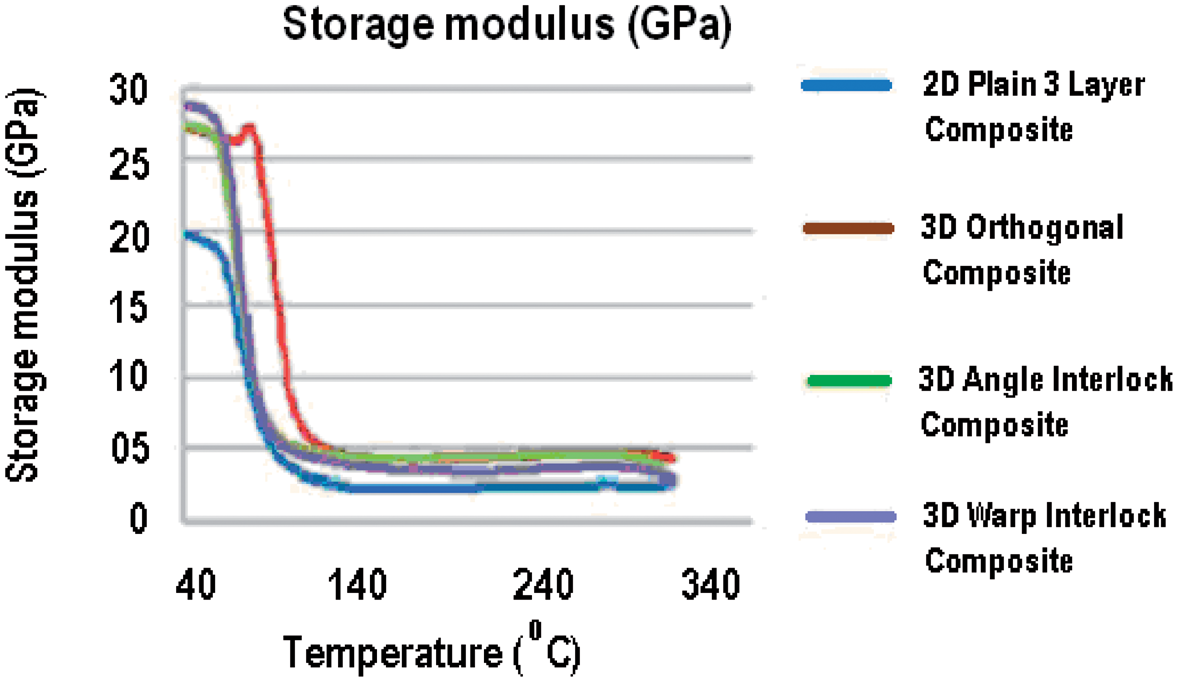
The glass transition temperature (Tg) in Figure 13 is defined by the peak value of Tan δ in the curves. The Tg has not changed too much by addition of nanopartilces. Also the values are almost similar for all composites except 3D orthogonal woven composites.
Tan δ for nanocomposites with different reinforcement structures.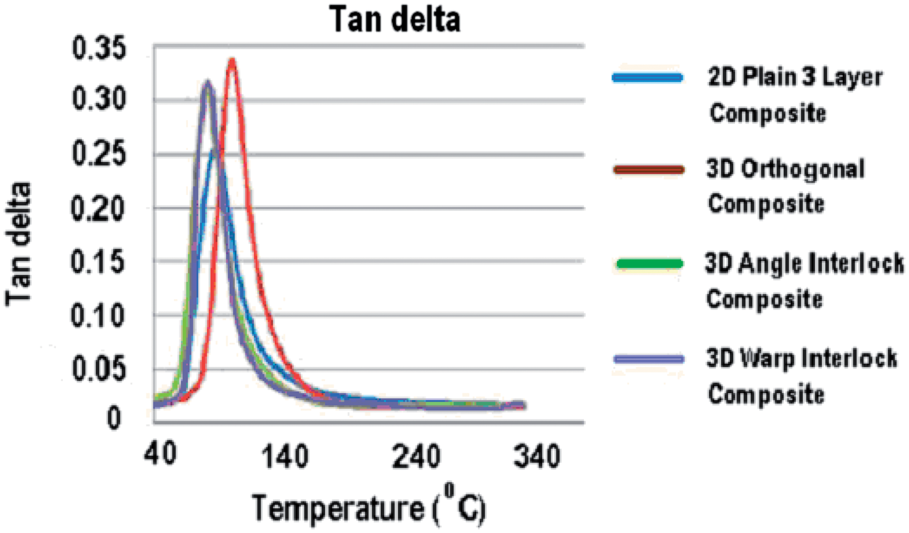
The Tan δ values of composites filled with fly ash are higher than that of the unfilled epoxy matrix, which proves that the addition of fly ash enhances the damping capacity of epoxy resin. All fabric constructions showed improvement in damping capacity of composites after addition of fly ash. This fact may be explained by the addition of fly ash which increases the contributions of the hollow structure in fly ash and frictional damping, thereby leading to the increment of the loss of energy, and thus the damping loss factor increases.
Electrical properties
As electrical conductivity is the property of material, so there is no significant effect of fabric structure on the electrical properties. All values of surface resistivity of the composites lie in a narrow range of 4.2 × 10⁹ Ω.m to 4.8 × 10⁹ Ω.m. And the volume resistivity is also between 6.5 × 10¹⁰ Ω.m to 7.2 × 10¹⁰ Ω.m. As this value itself is so high, the change in the values of resistivity between the structures is not significant. Addition of particles improved the conductivity of the material in all cases. Results are shown in Figure 14 (a) and (b).
(a) Surface resistivity of composites and nanocomposites. (b) Volume resistivity of composites and nanocomposites.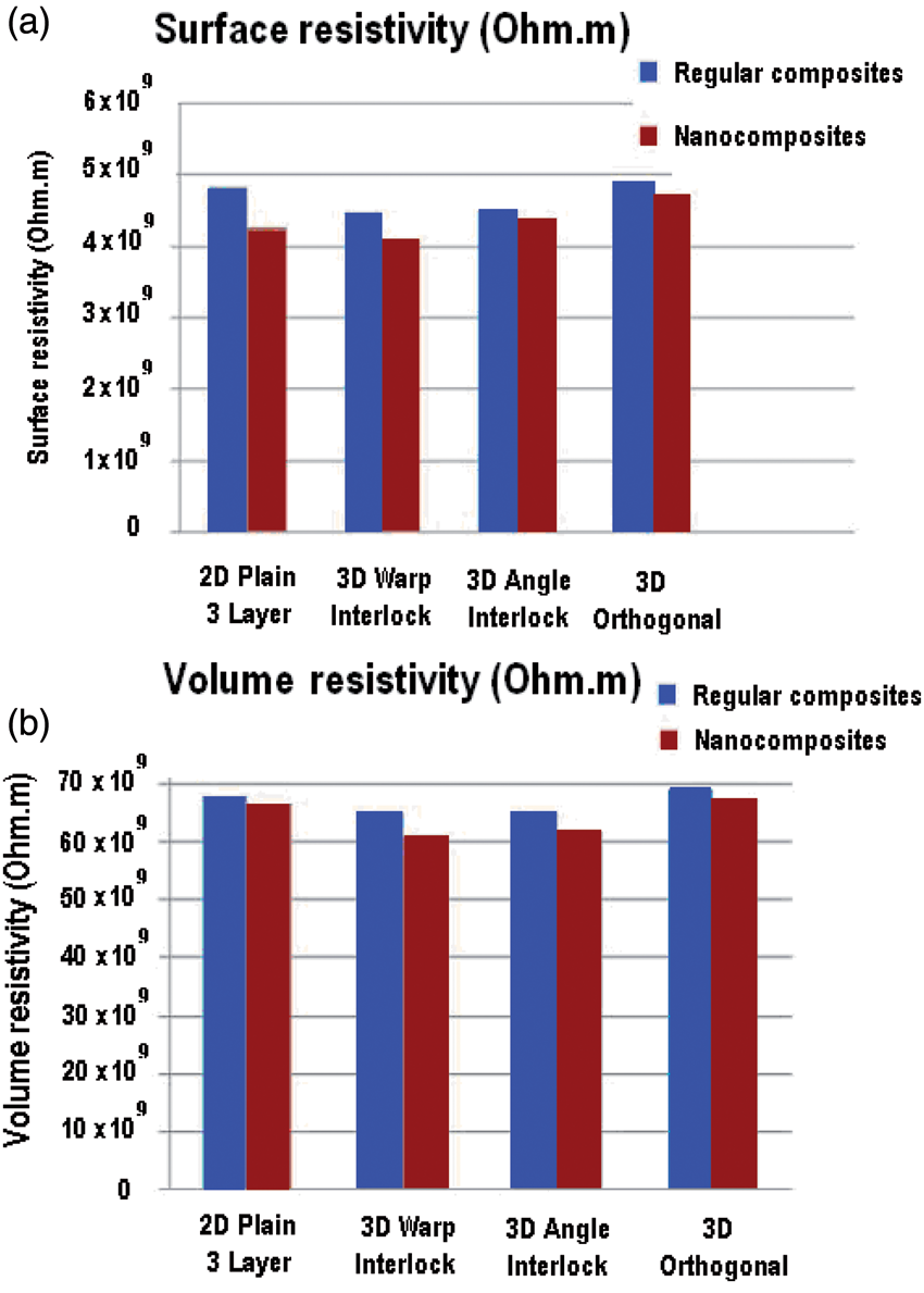
Electromagnetic shielding
As shielding effectiveness of the material is influenced by the conductivity of the material, slight improvement is observed in the SE value of the nanocomposites.
Figure 15 shows the shielding effectiveness in dB for both regular and corresponding nanocomposites. The addition of nanoparticles improving the conductivity of the matrix material enhanced the EM shielding of the nanocomposites.
Electromagnetic shielding of composites and nanocomposites.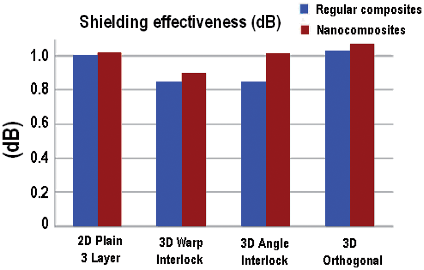
Conclusion
The concept of adding nanoscale filler in the matrix material with fabric reinforcement in a new three phase composite has been shown to be very successful. The fly ash nanoparticles needed for these composites were prepared by high energy ball milling technique. This method of preparation of fly ash nanoparticle was found as universal & quick, giving mean particle size of 450 nm. Functional properties of the nanocomposites were determined and compared with those of regular composites. All nanocomposites show improved knife penetration resistance compared to regular composites. However, addition of nanoparticle improved the breaking strength & energy of 2D plain woven composite to the maximum. The uniform distribution of nanoparticle in between the layers of plain woven composite could be the reason for giving maximum change in this case.
From DMA results, it is seen that storage modulus increased by significant amount while Tg remained almost unchanged for different composite samples determined by the peak in Tan δ. Therefore, the changes in thermo-mechanical properties were due to the physical presence of the nanoclay as opposed to changes in the polymeric network structure. Improvement in the conductivity of nanocomposite is observed due to addition of fly ash nanoparticle. This enhancement caused slight improvement in the shielding effectiveness of the nanocomposites. But both these changes are not so significant to be taken into consideration in related applications. This is attributed to properties of fly ash particles. Conductive particles can be used for further enhancement of EM shielding.
Footnotes
Funding
This work was supported by the project [grant number: DF13P01OVV004], in Czech Republic.
Conflict of interest
None declared.