
Abstract
Out-of-autoclave prepreg processing requires evacuation of volatiles in the early stages of processing to achieve an acceptable final void content. In this study, single prepreg plies were laid-up onto a glass tool to simulate a ply–ply interface, to gain an understanding of initial air entrapment and eventual removal mechanisms. The contact was recorded during processing with various edge breathing configurations to identify the relationship between evacuation pathways and contact evolution. The existence of preferential flow channels along the fibre direction of the material was demonstrated by characterizing the prepreg surface. Gas evacuation in those channels prevented contact during an extended ambient temperature vacuum hold. The contact between the prepreg and glass tool equilibrated around 80% during the ambient vacuum hold, and reached full contact at elevated temperature after a brief loss in contact due to moisture vaporization, when the resin pressure decreased to below the water vapour pressure.
Introduction
Void formation in composite manufacturing remains one of the primary processing problems because it is well known that voids have a detrimental effect on the mechanical properties of laminated composites. 1 Void formation in prepreg processes is usually suppressed by applying high pressures in either a press or an autoclave to dissolve volatiles into the resin. However, recent demands for more sustainable manufacturing processes, including out-of-autoclave (OoA) prepregs, have stimulated scientific interest in void phenomena because these processes use lower pressures that cannot suppress voids to the same extent as in the autoclave process. A lower consolidation pressure during vacuum-bag-only processing of OoA prepregs may be accompanied by an enhanced susceptibility to porosity.
To produce void free parts, processing parameters must be chosen carefully, based on a thorough understanding of void formation. Furthermore, a special prepreg microstructure is required to enhance gas evacuation prior to curing. Out-of-autclave prepregs are initially partly impregnated, consisting of a dry central fibrebed surrounded by resin-rich areas. 2 Before heating, and during the early stages of the curing cycle, the dry areas form permeable channels that allow gas evacuation. As heating begins, the dry microstructure is infiltrated by softening epoxy resin from the resin-rich areas. Full prepreg impregnation is desired before gelation; however, if concurrently, evacuation channels remain permeable in the early heating stages, they offer residual volatile extraction opportunities. 3
Various void generation and dissipation mechanisms will contribute to void formation during processing, based on the initial material structure and handling, lay-up and processing parameters. A general classification of voids has identified three major types: intraply voids within a single fibre layer, resin voids and interply voids between adjacent plies. 4 Intraply voids are initially caused by insufficient impregnation of the dry areas within the OoA prepreg structure. These voids will remain in the finished laminate if the resin content is insufficient, the resin viscosity profile does not allow full wetting of the dry fire regions or the resin pressure is insufficient during processing. Resin voids are induced during the prepregging process or during the cure reaction as volatiles are released or moisture is diffused out of the resin. Both intraply and resin voids have been addressed in previous studies.5–8
Interply voids between layers are caused by mechanical entrapment of air pockets during ply deposition. Material factors contributing to the initial interply air entrapment and distribution include ply surface topology and premature contact with the opposing surface, owing to tackiness. 9 Additional geometrical or processing entrapment factors during lay-up include ply terminations, material handling, lay-up conditions (temperature and humidity) and contamination. Geometrical and processing factors are more difficult to capture than material factors but, regardless of their origin, once entrapped between plies, isolated air pockets will remain as interply voids within the final part if they cannot be removed or consolidated during the manufacturing process.
The literature covering interply void formation in the OoA process is still very limited compared with what is known about resin and intraply void formation. To date, woven fabrics have been the primary focus of interply void research and initially represent the greatest fraction of total void content. 4 These voids generally shrink to nothing during processing; this is attributed to air evacuation through gaps created by the interlaced structure. The same phenomena cannot be transferred to unidirectional prepregs, since these have smoother surfaces than woven prepregs, as well as lower out-of-plane air permeability. 10
In-situ experimental techniques to characterize interply void formation are currently limited. Microcomputed tomography would be the ideal tool to capture the three-dimensional evolution of interply voids during processing, but current scan times are too slow to capture the temporal change during the initial vacuum application and the scan resolutions needed to capture the spatial distribution of interply voids are limited to small sample sizes.
Since the interply void formation mechanisms resemble the entrapment and evacuation of air between a tool–ply interface, a glass plate and optical camera may offer the speed and resolution to monitor void evolution in processing conditions. Replacing a multiple prepreg ply–ply interface in a laminate with a single ply applied to a rigid mould is likely to change the boundary conditions in this region of interest. The contact mechanics between the resin at the tool–ply interface will probably differ from those of an isolated bubble surrounded by resin. Moreover, the complex nature of transverse compaction stresses transferred at different angles through ply nesting may influence the contact and air flow pathways. Clearly, this technique is not without limitations, but it can offer qualitative insights to capture the void evolution in different processing conditions in relevant time intervals.
The transparent mould approach has been used by Bloom et al. 11 to study the effect of ply consolidation of different ply deposition techniques, such as hand lay-up and roller-assisted methods, and the influence of flexible bagging consumables on the applied pressure distribution in prepreg processing. In a separate study, Hamill et al. 9 also used a glass plate and camera to investigate the influence of material and processing parameters on surface porosity, and identified air entrapment as the primary source of large surface pores after cure. Additional information about the height of the void can be obtained by surface roughness measurements. Lukaszewicz and Potter 12 measured the surface roughness of uncured autoclave and OoA fibre placement grade prepreg tapes, and concluded that rougher prepreg surfaces would influence the cured laminate interply void content.
In light of the fact that interply voids contribute to the degradation of mechanical properties, coupled with a shift towards low pressure processing, a need exists to capture the initial distribution of these voids and describe their evolution during processing in order to understand which gas evacuation mechanisms are available to minimize cured part porosity. In this study, the surface roughness of an OoA prepreg was examined to evaluate the texture and properties of the material in its uncured state, so as to inform void formation in a unidirectional prepreg. This characterization was followed by measurement of the contact evolution of the OoA prepreg ply on a glass tool using different in-plane breathing configurations. The images were processed to determine whether the contact mechanisms changed during ambient and elevated temperature processing to understand the air evacuation mechanisms of interply voids during OoA prepreg consolidation.
Material constitution
Out-of-autoclave prepreg materials are supplied partly impregnated, consisting of dry-fibre and resin-rich areas that will ideally become void free after elevated temperature curing. Figure 1 shows an example of a processed computed tomogram of an uncured Cytec Engineered Materials’ Cycom® 5320 OoA prepreg microstructure; this image was generated using the procedure outlined by Helmus et al.
13
The carbon fibre prepreg, with a fibre density of 1.77 g cm−3, was supplied with an epoxy resin that accounts for roughly 33 wt% of the material. This particular prepreg was supplied with a relatively stiff single-sided paper backing. The prepreg is a vacuum-bag-only curable prepreg allowing a curing temperature of either 93℃ or 121℃, according to the manufacturer’s datasheet.
Cross-section of an uncured unidirectional prepreg.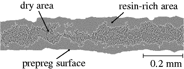
Although prepregs are machine-made by a commercial process, Figure 1 reveals that the prepreg material has an irregular resin distribution on the surface that can lead to variations in the prepreg cross-section. This induces variations in the prepreg fibre volume fraction, which in turn leads to variability in the in-plane air permeability. Variability in the out-of-plane permeability may also occur. The scanning electron micrograph of the prepreg surface shown in Figure 2 identifies point-to-point variations in the resin distribution that might promote local areas of higher out-of-plane air permeability, compared with adjacent resin-rich regions.
Scanning electron micrograph of a unidirectional prepreg surface before processing.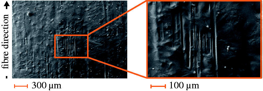
Figures 1 and 2 highlight the rough surface of the prepreg, which may be affected not only by variations in the resin distribution due to manufacturing techniques but also as a result of material transport, storage and handling before final usage. For a better understanding of the surface properties, surface roughness scans were conducted using an Alicona G5 optical micro-coordinate measurement system. A 50 mm × 25 mm sample was mounted on a glass slide and sputter-coated with 30 nm of gold prior to scanning. The centre surface topology of a 10 mm × 10 mm region of both the backing paper and the non-backing paper sides of the prepreg are shown in Figure 3.
10mm × 10mm surface of an uncured unidirectional prepreg. Fibres are oriented in the x-direction.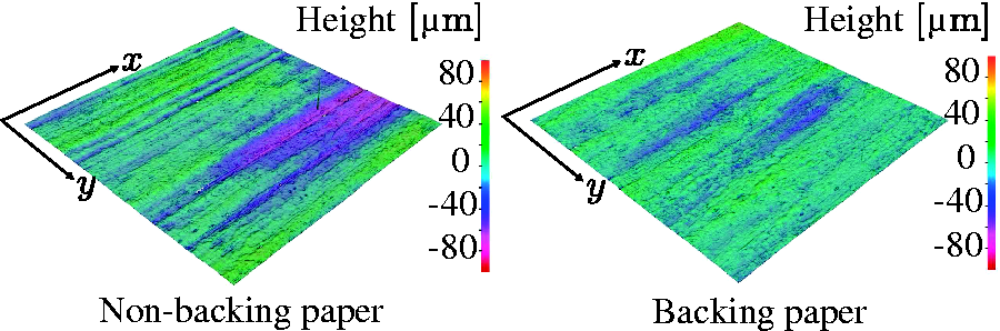
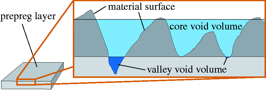
The maximum volume entrapped by each side was determined using a surface scan. The void volume of the surface was subdivided into core and valley void volumes, as shown in the cross-section of a prepreg layer in Figure 4, using the bearing area curve. The values for each area are presented in Table 1 and indicate that there is a marked difference in surface roughness between the backing paper and the non-backing paper side of the prepreg. As a result, the non-backing paper side of the material will entrap a larger volume of air than the smoother backing paper side. To capture the worst-case scenario, coupled with the probable manufacturing procedure of laying up the non-backing side of the prepreg, the non-backing side of the prepreg was placed onto the glass tool.
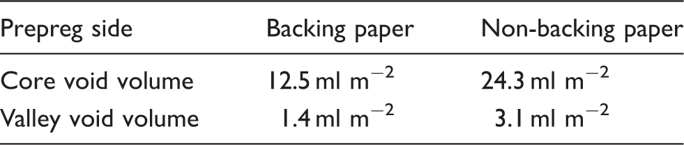
The surface roughness of the prepreg determines both the initial volume of entrapped air and the ability to evacuate air from the lay-up. A corduroy surface structure running parallel to the fibre direction generated interconnected pathways for air evacuation in the interply region until the combined compaction and evacuation collapsed this structure.
As represented in Figure 5, the interply zone (1) may not be the only evacuation possibility. Air may flow from the interply zone into the intermediate dry layer based on the pressure differential between the regions and the opposing resin viscosity. Subsequently, air can either be removed through the evacuation channels (2), remain in the intermediate layer (3) or migrate in the out-of-plane direction (4). Void compression (5) or dispersion (6) are also possible and are governed by the applied pressure.
Interply void removal mechanisms.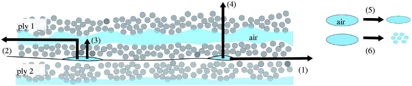
According to Persson et al., 16 the surface roughness determines the entrapped void volume and possible evacuation pathways, but also has an enormous influence on tack (the pull-off force), which in turn has an influence on air entrapment. 9 Therefore, void spaces may remain in the interply region because the prepreg fibres will oppose bending and the high viscosity resin on the surface might not flow sufficiently when cold. The pressure in these void spaces will depend on the resisting gas pressure at the ply–ply interface, or on whether the resin pressure can either dissolve the gas into the resin or redistribute the gas within the ply, such as the dry region within a partially saturated prepreg.
Experimental approach
In this study, the contact evolution between a prepreg ply and a glass plate was recorded to evaluate the interply void formation. The glass surface does not have the same properties as a prepreg, but might correspond more closely to a well debulked prepreg surface. More importantly, this technique enabled real-time imaging of the contact evolution of a relatively large sample area during processing.
Test set-up and image processing
Several trials with different edge breathing conditions were carried out by laying up a single 300 mm × 300 mm prepreg ply onto a 10 mm thick untreated glass tool. The prepreg plies were prepared at the same time and stored in a freezer at −20℃ in individually sealed bags to maintain the same initial material conditions between trials. The prepreg ply was laid-up by hand and pressed against the glass tool before placing the consumables and installing the vacuum bag. The bagging arrangement consisted of a non-perforated release film, a vacuum bag, four layers of breather, a 4 mm thick heater pad, four thermocouples and an aluminium caul sheet of 3 mm The aluminium caul sheet was used to even out heat distribution from the heater pad and consistently apply transverse pressure to the prepreg ply in each trial, avoiding the variations in pressure encountered with a flexible membrane bag.
11
Edge breathing dams were made of sealant tape wrapped in fibreglass (unless otherwise specified) and located around the edge of the ply. A cure cycle corresponding to the manufacturer’s specification was applied using a closed-loop controller for the heater pad, while a vacuum port adjacent to the ply was connected to a vacuum pump. The experimental set-up is shown in Figure 6.
Glass tool set-up used for contact experiments.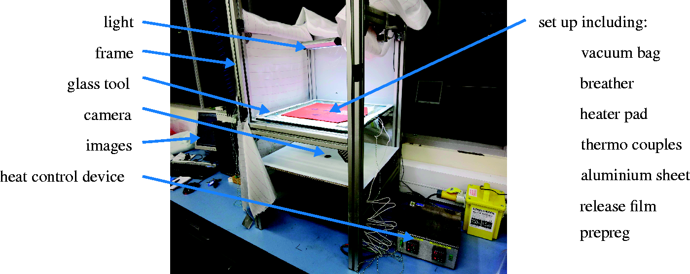
A DMK 2 mega-pixel monochrome digital camera was placed underneath the glass tool to capture images during the process. Lighting conditions of the images were improved by an additional light installed above the glass tool to provide the most diffuse illumination possible around the edge of the ply while avoiding reflections from placing direct lighting underneath the sample. Images were processed using MATLAB®. First, edges were cropped, reducing the raw 260 mm × 220 mm images to 210 mm × 170 mm to eliminate fish-eye effects at the corners. Second, an invariable threshold value was used for each sequence to convert images into binary images, consisting of black and white pixels. The contact area was determined for each image by counting the number of black pixels, excluding the circular camera reflection located in the middle of the images. The contact area was related to the total pixel count of each image, and given as a percentage.
Test matrix
To investigate the air evacuation pathways described in Figure 5, air removal was evaluated using four different configurations. The first configuration consisted of full edge breathing around all four prepreg sides, using edge breathing dams consisting of sealant tape wrapped in fibreglass. Out-of-plane air evacuation was restricted by a non-perforated release film (Figure 7(a)). In the second configuration, all four edges as well as the release film were sealed to the glass tool, restricting air to relocation or compression within the prepreg ply (Figure 7(b)). In the third configuration, evacuation pathways were sealed by 0.025 mm thick flash tape wrapped around the prepreg edges to restrict gas flow to the glass-tool–ply interface region (Figure 7(c)). Finally, edge breathing was placed on one side only, sealing the other three edges with sealant tape and closing off the surface with non-perforated release film (Figure 7(d)). Although similar in-plane flow should occur between the one-sided and the full edge breathing experiments, the one-sided configurations were used to determine whether a contact gradient was present during evacuation. Three repeats were conducted for each boundary condition.
Four different experimental set-ups used to investigate air evacuation pathways: (a) full edge breathing; (b) sealed edges; (c) evacuation channels sealed; (d) one-sided edge breathing.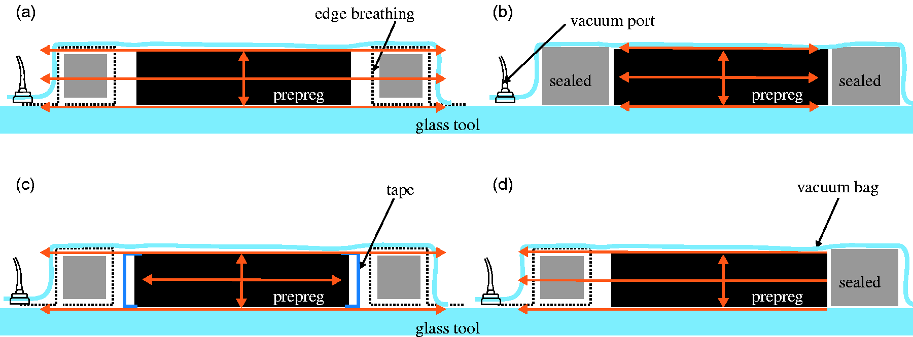
Results and discussion
Contact evolution over time
At the beginning of each experiment, almost no contact points are present. A rapid increase in contact occurred after the vacuum was applied. Contact patterns after 10 min, 1 h and 10 h into the vacuum hold are presented as binary images in Figure 8 for one repeat from each configuration, showing the contact evolution. Contact initiates at random locations and then evolves from these initial contact points. Contact areas were more likely to grow from these initial points rather than the smaller areas of contact preferentially growing to become connected. This offers some insight into how the entrapped air migrates in the interply region to create void spaces in the non-contact areas. Furthermore, the non-contact regions seem to stay interconnected, running parallel to the prepreg fibre direction, which remained identifiable throughout every experiment, regardless of the edge breathing configuration. Overall, these observations suggest that the non-contact areas contribute to the air evacuation in the interply region. An initial visual examination of Figure 8 revealed no distinct difference in contact patterns between different edge breathing conditions. To determine whether a preferential contact pattern occurred between test configurations, an amplitude density function of the mean contact area along and across the fibre direction was plotted. No statistically significant difference was observed between the width of the interconnected non-contact regions.
Contact evolution during the vacuum hold for the four edge breathing conditions, binary images (210 mm × 170 mm). Black areas indicate contact between glass plate and prepreg; the black circle in the centre of each image is the camera reflection.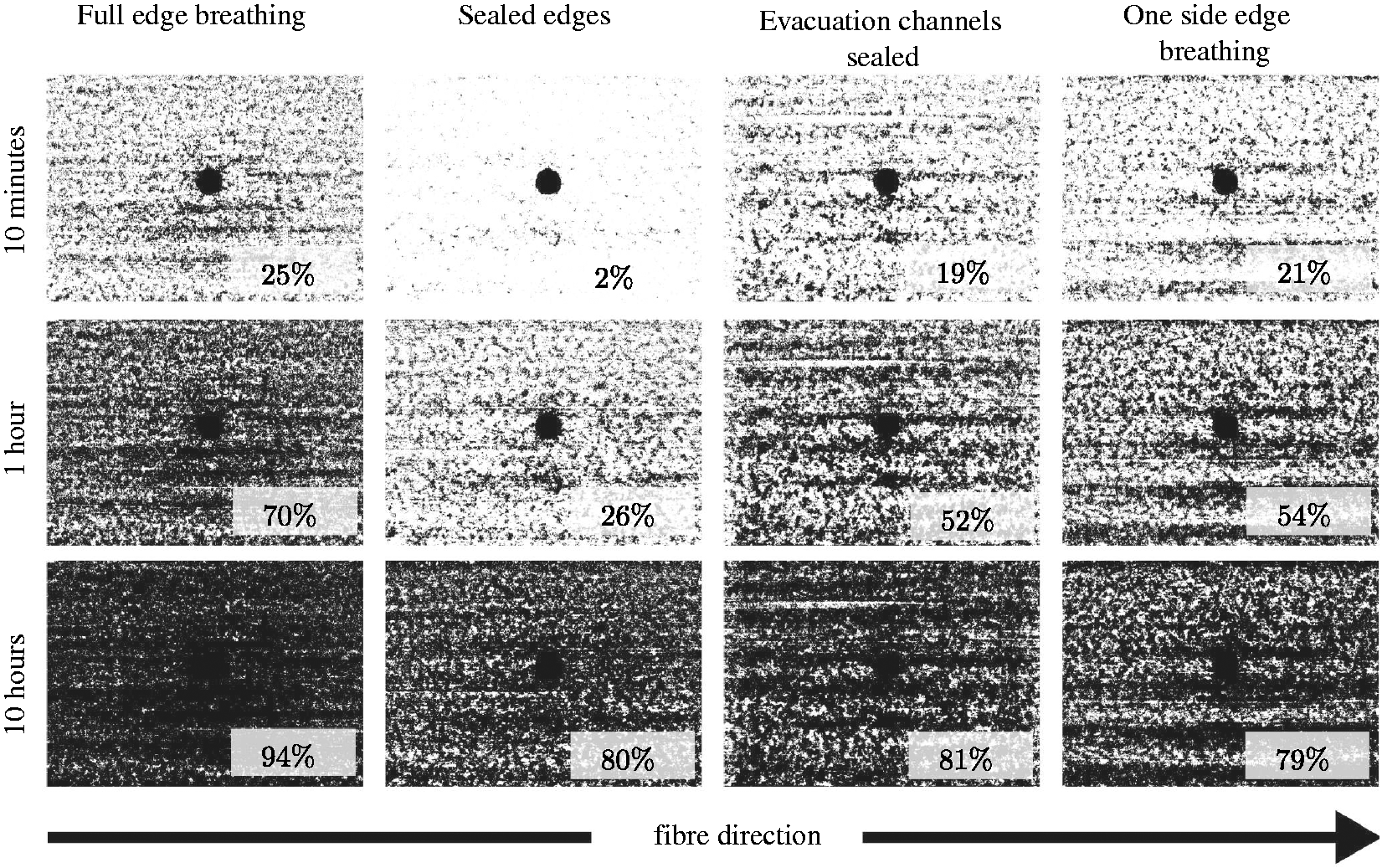
Figure 9 shows the contact evolution during a 12 h ambient temperature vacuum hold for all three repeats for the four edge breathing conditions. Contact increases with time and reaches equilibrium after about 6 h, where the final contact area remains between 70% and 90% for all edge breathing conditions.
Contact evolution during vacuum hold for different edge breathing conditions.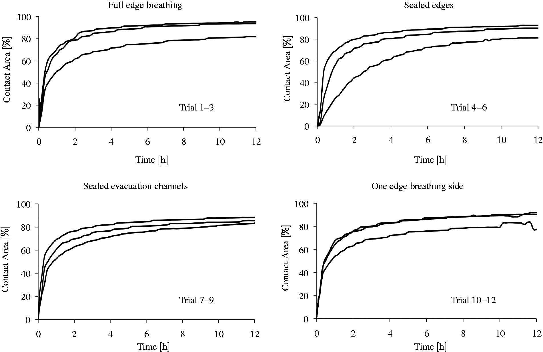
The variability between trials does not allow for a clear distinction between the effect of the different edge breathing conditions on ambient evacuation mechanisms. The inconsistent and localized nature of air entrapment was also observed at the tool–ply interface9,11 and confirms the random nature of prepreg surfaces.
After the 12 h ambient vacuum hold, the prepreg was heated at 2℃min−1 to 93℃; the contact evolution is shown in Figure 10. Each trial reached full contact during the elevated temperature processing stage of the study; however, after approaching 100% contact, all configurations showed a drop in contact at around 90℃, before eventually returning to full contact again. Moisture was considered as a possible cause of the loss in contact, therefore the effect of moisture devolution was investigated by comparing estimates of the water vapour pressure with the resin pressure. If the resin pressure is higher than the water vapour pressure, moisture will remain in solution.
7
The dashed vertical line in Figure 10 is the cross-over point where the resin pressure becomes less than the water vapour pressure, and a loss in contact was observed.
Contact evolution during heat application for different edge breathing conditions.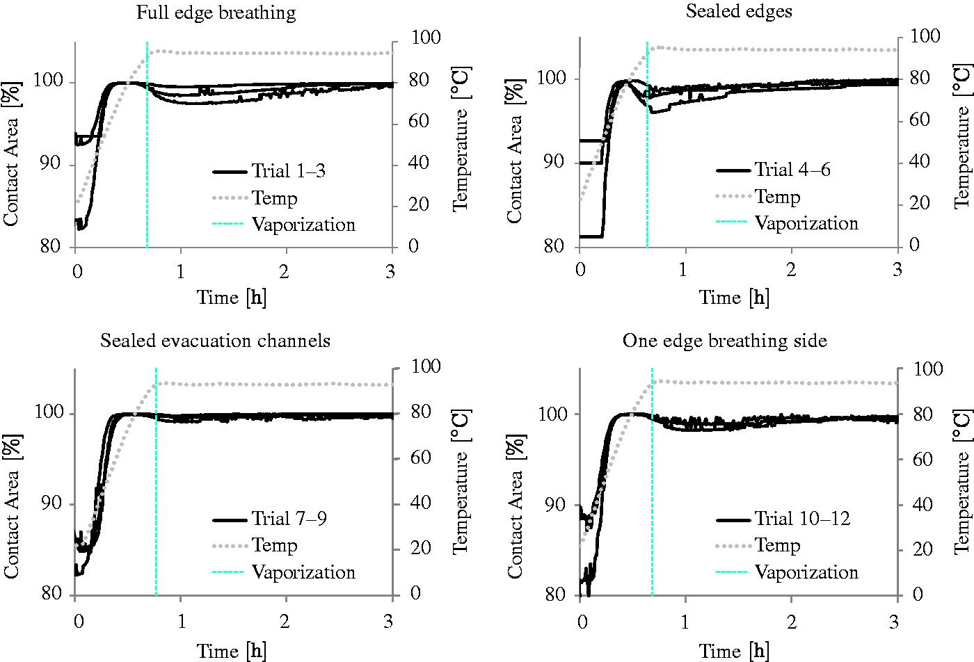
Changes in water vapour and resin pressure during elevated temperature processing are shown in Figure 11. The water vapour pressure was estimated by the model developed by Kardos et al.,
7
which describes the relationship between water vapour pressure, P, in bars and temperature, T, in degrees Celsius
Water vapour and resin pressure development during heat and vacuum application compared with contact evolution under full edge breathing conditions. The cross-over point of the water vapour and resin pressures caused a loss in contact due to moisture diffusion out of the material. Load share between fibres and resin during processing; σf is determined by the fibrebed compaction curve.


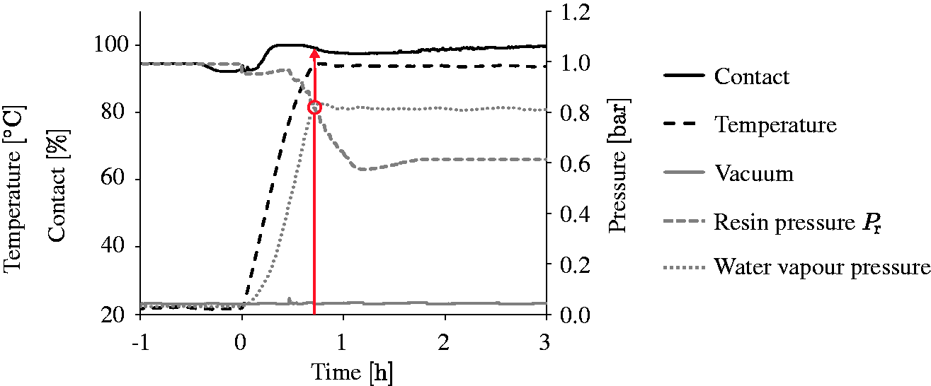
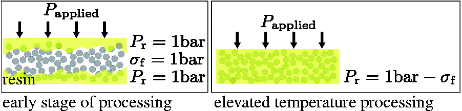
The load shared between the resin and fibre regions of an OoA prepreg was described by a previously developed model, 18 which relates the thickness change of a prepreg to the resin flow into dry-fibre areas. The initial resin pressure in OoA laminates is much higher than would be expected for autoclave prepreg processing because the partially impregnated nature of OoA materials effectively places the resin in series with the fibrebed. As the semi-solid resin film softens during elevated temperature processing, the resin saturates the fibrebed and the applied load is shared. As a result, the resin pressure in Figure 11 becomes constant after 1.5 h into the heating, owing to the termination of the model as soon as full resin impregnation is reached. The resin pressure would be expected to decrease as the resin shrinks after gelation. 19 However, the resin is in a pre-gelled state for the results shown in Figures 10 therefore, the effects of chemical shrinkage are not encountered in this study.
In Figure 11, the resin pressure exceeds the water vapour pressure at around 90℃ and a decrease in contact between the prepreg ply and glass tool was observed at this point. This suggests that absorbed moisture is released by the material into the interply zone, which may contribute to the drop in contact. The cross-over temperatures of the water vapour and resin pressure are indicated in Figure 10. The loss in contact in the sealed edges configuration starts earlier than the other trials in Figure 10 because of the additional entrapped air at the tool–ply interface.
The final interply void content appears to be independent of the edge breathing conditions. This was an unexpected result, especially for the completely sealed edges configuration. Since air cannot be evacuated out of the prepreg, air removal options (1), (2) and (4) in Figure 5 are not available; therefore, air initially located in the interply region must relocate to the intraply dry area of the prepreg (3), be compressed (5) or disperse (6).
The air initially entrapped in the interply region has probably relocated to the intraply dry area in the sealed configuration. This assumption is supported by a quality study of OoA laminates conducted by Centea and Hubert, 20 who processed prepregs with sealed edges. Compared with laminates processed with full edge breathing, the laminates with sealed edges had an increased void content in the dry intraply area. After we processed plies with sealed edges, the removal of the cured ply from the glass tool was different from other configurations. Fibres that were located in the middle of the prepreg remained dry after processing and induced ply splitting during removal.
Contact evolution with temperature
The contact evolution is plotted as a function of temperature in Figure 13 to analyse the relationship between temperature, resin viscosity and ply contact. The resin viscosity was calculated by published cure kinetics and viscosity models.
21
For all four edge breathing conditions, the initial contact at room temperature stagnates between 70% and 90%. Full contact was eventually achieved in all four configurations, but contact of set-ups with breathable edges evolved almost steadily after 35℃, whereas the contact for the sealed edge configurations remained constant up to about 50℃. This behaviour indicates that entrapped volatiles remain at the tool–ply interface, preventing resin flow into the interply region. If the areas of non-contact were empty spaces, with an equivalent pressure to the vacuum bag, resin would flow into the non-contact areas at the same rate as for the other experiments. As a result, in the sealed edge configuration, air relocation cannot occur until the viscosity is sufficiently low to allow air flow into the intermediate layer.22,23
Contact evolution with temperature for different edge breathing conditions.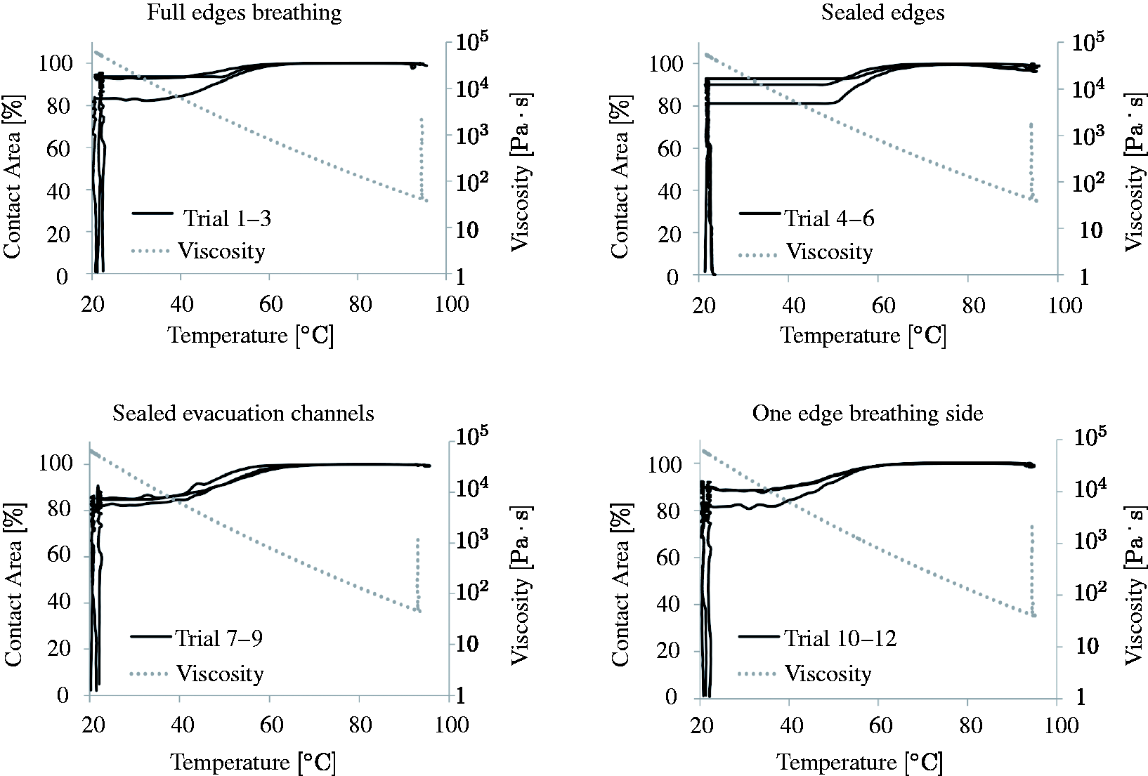
Directional contact evolution
The contact images were analysed for a spatial gradient to determine whether the contact preferentially initiates at the edge of the ply and temporally increases towards the centre, or vice versa. The images were subdivided into three different areas, depending on the breathing configuration being tested, as shown in Figure 14.
Areal subdivision for directional contact evolution: (a) one-sided edge breathing tests, (b) full edge breathing.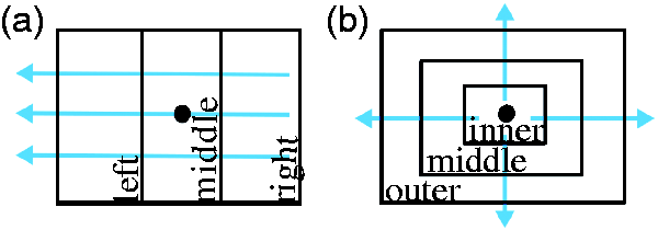
The one-sided edge breathing trials were evaluated by subtracting the left area from the middle area (Figure 15(a)) and the middle area from the right area (Figure 15(b)), according to the regions defined in Figure 14(a).
Gradient in contact evolution for one-sided (left) edge breathing.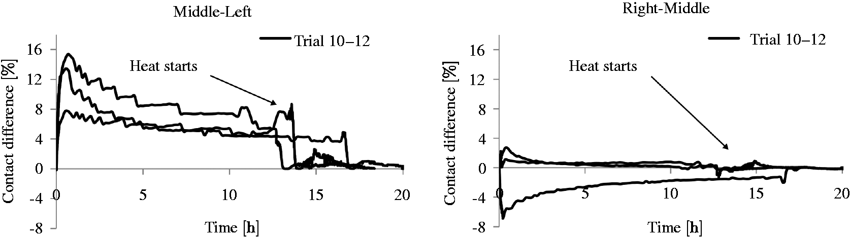
The configurations with full edge breathing were also subdivided into three regions, but the contact regions were arranged as concentric rectangles, as shown in Figure 14(b), since air could be extracted around all four edges of the ply. Figure 16 depicts the difference between the outer and middle regions, and the difference between the middle and inner regions.
Contact gradient evolution for the full edge breathing configuration.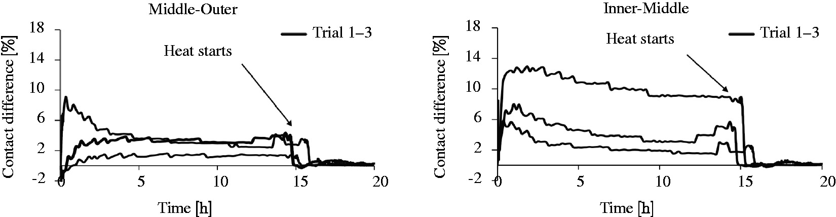
From the analysis in Figures 15 and 16, it appears that the ply contact evolves more slowly in areas close to the edge of the ply that allows air evacuation. This indicates that the non-contact areas create air evacuation pathways, which in turn inhibit contact. In the case of full edge breathing, contact evolves from the middle of the ply, whereas contact for the one-sided edge breathing initiates from the side opposite the edge breathing. Overall, contact evolved more quickly in the middle but this could be related to local phenomena within the ply that influence property variations. For example, variations in the surface roughness, or the in-plane and out-of-plane air permeability coefficients could influence how contact forms between the ply and the glass plate.
The linear contact gradient used in Figure 14(a) was applied to both the one-sided edge breathing and the full edge breathing trials. This analysis allowed us to compare whether the contact gradient observed in Figure 15(left) was an anomaly created by the experimental set-up. The results of this analysis are shown in Figure 17, and confirm that the experimental set-up did not create the linear gradient because a contact gradient was always observed in the one-sided edge breathing configurations, whereas contact was observed to evolve from both sides in the full edge breathing configuration. The contact gradient disappeared as soon as heat was applied to both breathing configurations.
Comparison of the contact gradients in the full edge breathing and one-sided edge breathing configurations.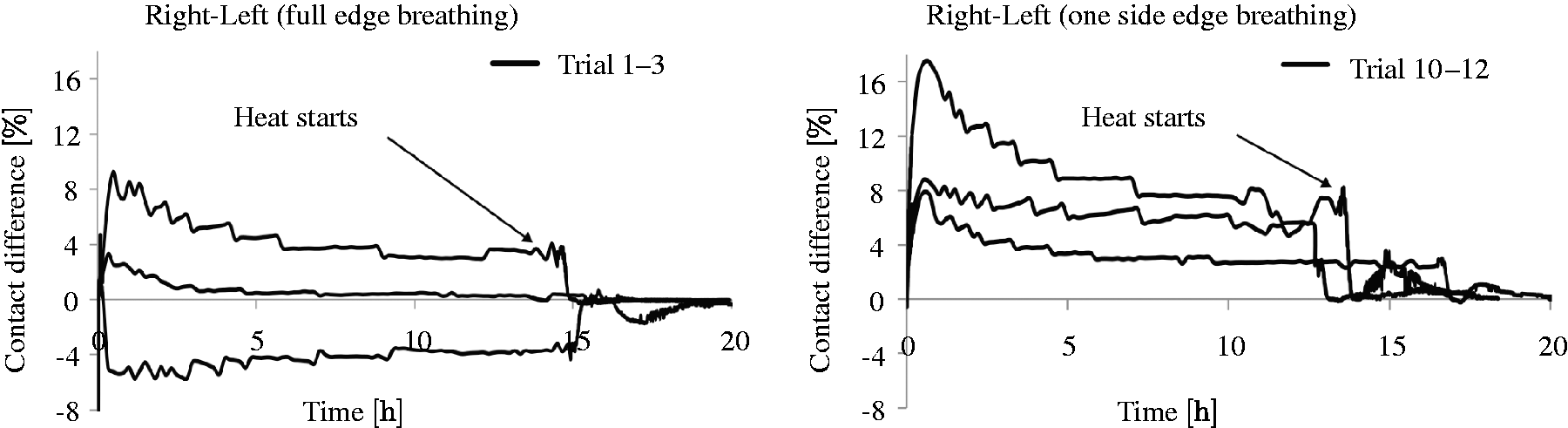
The evacuation pattern of unidirectional OoA prepregs was evaluated for contact evolution along and across the fibre direction, in the x- and y-directions identified in Figure 3. For contact across the fibres (y-direction), pixel columns were averaged and for contact along the fibres (x-direction), pixel rows were averaged. Results along the fibre direction are shown in Figure 18(a) for full edge breathing and Figure 18(b) for sealed evacuation channels; contact along the fibre direction is shown in Figure 18(c) and (d).
Contact in x- and y-directions for 10 min, 1 h 10 h and after heating.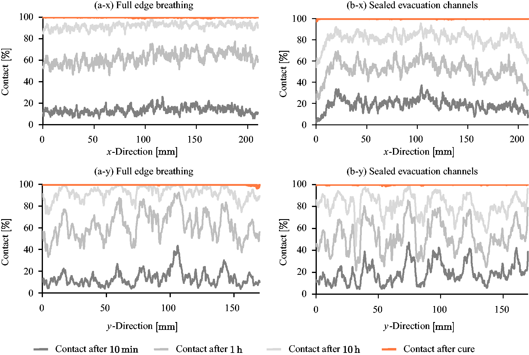
Higher variability was observed across the fibres (in the y-direction) than along the fibres (in the x-direction), as can be seen in Figure 18(a) and (c) as well as Figure 18(b) and (d). This variability reflects the air evacuation pattern of unidirectional prepregs. Interconnected valleys along the fibre direction serve as evacuation pathways and entrapped air impedes contact until heat is applied to soften the resin, and enable a combination of resin and air flow. A direct comparison between the full edge breathing and sealed evacuation channels after 10 h into the vacuum hold is shown in Figure 19, to accentuate the difference in contact across the fibres between these two configurations.
Contact in the y-direction for full edge breathing and sealed evacuation channels after 10 h into the ambient temperature vacuum hold.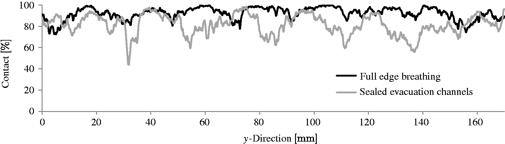
In general, the contact profile for sealed evacuation channels is rougher than the full edge breathing profile. Expanded non-contact areas are present, which is in agreement with wider white bands observed in the binary images (Figure 8).
This observation supports the assumption that air has to be evacuated between the glass tool–prepreg interface when the intraply air evacuation channels of the prepreg are sealed. Accordingly, forcing air evacuation in the interply zone decreased the percentage of ply contact before heating.
Conclusions
The surface of OoA prepregs was investigated to establish an understanding of air entrapment between plies. The contact evolution between a glass plate and a prepreg ply was measured during the consolidation process under various edge breathing conditions, to identify the interply air evacuation mechanisms in unidirectional OoA prepregs.
The surface roughness of the prepreg ply was influenced by the nature of the unidirectional fibrebed: surface valleys form a corduroy texture along the fibre direction. As a result, contact was more pronounced along the fibre direction than across the fibres. Contact was observed to evolve from the initiation points into larger contact areas, instead of by many smaller contact areas connecting. In fact, non-contact areas (considered to be interply voids) relocated into the valleys of the prepreg surface, and remained mostly visible throughout the ambient vacuum hold. These observations indicate that surface roughness valleys serve as interply air evacuation pathways for entrapped air.
To investigate the effect of a region of a ply becoming isolated from the vacuum source during processing, the contact evolution of completely sealed plies was measured; the results suggest that air relocates into the dry intraply region of partially saturated prepregs and does not remain in the interply region. However, variability in contact between repeats of the same test configuration suggests that local phenomena are likely to occur. This can be attributed to property variations within the prepreg: random resin and fibre volume fraction distributions influence the surface structure as well as the permeability in the in-plane and out-of-plane directions. The out-of-plane permeability determines the amount of entrapped air, whereas the in-plane air permeability mainly influences the evacuation time frame and the corresponding contact evolution.
A drop in contact at around 90℃ suggests that the contact evolution in the interply zone was not solely determined by air initially entrapped between plies, but is also affected by absorbed moisture, which was released by the material at elevated temperatures.
Overall, a test method was established to investigate the interaction of the phenomena that define the final part quality in regards to air entrapment between plies. The results presented here are an important first step towards a better understanding of the phenomena associated with the interply void formation in OoA prepregs. This study provides a basis for a more widespread analysis of interply void formation.
Footnotes
Acknowledgements
We would like to acknowledge the Chair of Biomedical Physics at Technische Universität München for the acquisition of computed tomography data, Alicona UK Ltd for the generation of surface roughness images and data and Dr Dominic Bloom for insightful discussions.
Declaration of Conflicting Interests
The author(s) declared no potential conflicts of interest with respect to the research, authorship, and/or publication of this article.
Funding
The author(s) disclosed receipt of the following financial support for the research, authorship, and/or publication of this article: This work was conducted within the framework of a G8-2012 project (Material Efficiency: A First Step Towards Sustainable Manufacturing) between the University of Southern California, McGill University, the Technische Universität München and the University of Bristol. Funding for this work was provided by the German Research Foundation (contract number DR 204/5-1) and the UK Engineering and Physical Science Research Council (grant number EP/K025023/1).