






Abstract
During composites manufacturing with partially pre-impregnated fibers (i.e. “prepregs”) in Out-of-Autoclave processes, non-impregnated fabric cross-sections serve as air pathways to evacuate entrapped bubbles of air, moisture, or volatiles. The bubbles trapped within a laminate during processing lead to decreased structural performance. In this work, the motion of resin and bubbles during the processing of a characteristic prepreg is directly visualized in situ. This is performed utilizing a previously developed flow visualization technique under known pressure and temperature conditions. This study investigates the processing conditions under which a bubble succeeds or fails to meet and coalesce with available air pathways in order to escape the laminate. A key finding of this study is that tunable process parameters, such as pressure and temperature, are less important for successful bubble removal as compared to the initial state of resin impregnation in the prepreg. Prepregs with initially high states of resin impregnation will often fail to draw bubbles into air pathways through the center of fiber tow cross sections, whereas prepregs with initially low states of resin impregnation have clear pathways for bubbles to meet local resin flow fronts, coalesce, and escape. The relevant literature on the motion of bubbles in confined spaces is discussed. It is observed that small Capillary number theory (i.e. Ca < 0.01) under predicts the relative velocity of bubbles, and the faster than expected bubble transport is likely due to effects given by the bubble aspect ratio via the fibrous micro-channel geometry.
Introduction
A primary challenge in composites manufacturing is obtaining a sufficiently low void content. It has been shown that a high porosity (>1%) can degrade mechanical properties, 1 thus decreasing composite quality and increasing design risk. Advani and Sozer 2 summarized how the autoclave composites process forms composite laminates from pre-impregnated fibers (i.e. “prepregs”) and is able to suppress void formation by applying consolidation pressure to the laminate at high temperature until the laminate cures. Despite the reliability of the autoclave process, it is expensive and the part size is constrained by the size of the autoclave.
“Out-of-Autoclave” (OOA) composite processes were developed to mirror the autoclave process without the need for an autoclave in order to alleviate the size constraints and lower capital costs. 3 Levy et al. 4 describes the well-known problem of how air can become trapped in between prepreg plies during processing when prepreg plies are stacked together due to poor intimate contact between them. In fully impregnated prepregs, these inter-laminar pockets of entrapped air in the resin have no means of escape from the system. In the autoclave process, the high applied pressure is able to suppress these volatiles into the resin and is not available during OOA processing. 5
The challenge of using vacuum pressure only to process prepregs is the evacuation of gases from the laminate prior to consolidation and cure, because atmospheric pressure is the maximum applied external pressure. 6 OOA prepregs are partially impregnated with resin. The dry (non-impregnated) fibers in the initial state of the prepreg form a connected network of air pathways across the laminate, either in-plane or through the thickness, which is necessary to evacuate the air from the system before final consolidation and cure. This network of pathways permits air, moisture, and other volatiles to be evacuated from the laminate through a vent port.
During OOA, specially designed partially impregnated prepreg plies are processed in an oven under vacuum pressure. Partially impregnated prepregs are available in a variety of designed “resin configurations.” Figure 1 schematically shows two of these options: Figure 1(a) shows a woven fabric with a layer of resin film laminated to one side of the fabric; Figure 1(b) shows a similar woven fabric where resin is applied to both sides of the fabric, where the interstitial space between fiber tows is occupied with resin and the fibers within fiber tows remain dry and serve as the air pathways.
Schematics of partially impregnated prepregs: (a) resin film on one side of a dry fabric and (b) resin film on both sides of a dry fabric.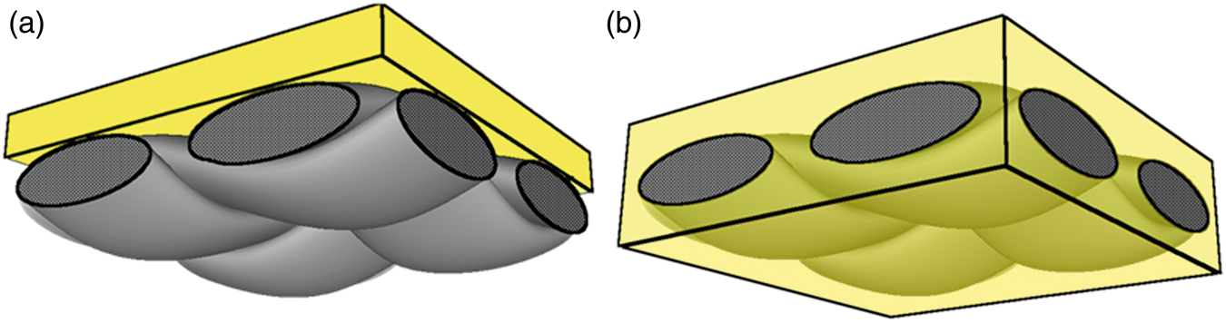
Initial resin distribution (or impregnation) is a major factor that dictates if it is possible to evacuate the air from the system. The clear advantage of the example prepreg depicted in Figure 1(a) is that bubbles cannot become entrapped between laminae. Alternatively, the prepreg in Figure 1(b) is constructed from resin films on both sides, leaving only the dry tow cross-sections to serve as air pathways. The presumption for such prepregs is that air, which is trapped between laminae during layup, will migrate into air pathways and can thus be evacuated from the laminate. This is illustrated schematically in Figure 2, where light blue arrows are shown to illustrate open and closed porosity migration towards prepreg dry areas and ultimately vented out.
A schematic showing the distinction between connected porosity and unconnected voids. Bubbles must migrate into air pathways in order to be vented from the laminate.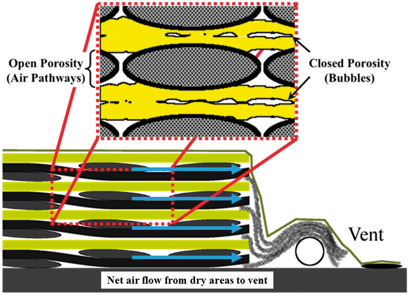
Bubble transport during composites processing has been studied by many authors;1,5,7–13 however, the available literature of bubble transport is predominately in the context of resin transfer molding (RTM) processes. In RTM-type processes,1,5,7,11–13 a net resin flow is present from an inlet port to a vent port, driving bubbles to travel in the direction of flow through the compacted fiber preforms. The modeling presented in these types of studies focuses on bubble movement through tight constrictions
7
and bubble break up.5,11 Bubble formation has been described to primarily depend on the Capillary number (

Here, μ is the resin viscosity, V is the velocity of the resin being injected, and γ is the surface tension between the resin and fibers. 1 When the capillary uptake of resin into fiber tows happens at a significantly different rate (i.e. higher or lower) than macroscopic resin flow through the fiber preform (i.e. around fiber tows), the resin flow pattern will form enclosed pockets of air inside or outside fiber tows as the resin fills the preform – thus leading to the formation of bubbles.
Gangloff et al.8,10 presented computational analyses that explored the effects of porous media walls on a bubble surrounded by resin moving through a micro-channel, studying how bubbles and resin transport together through inter-tow spaces. This micro-channel was surrounded by porous media walls with assigned permeability values to describe the resin seepage flux into the walls as a bubble and resin pass through the channel. It was shown that the permeability of the porous media walls has a strong effect on the ability for bubbles to outrun resin flow fronts and escape. The previous work showed that the shape of the bubble and resin flow front was affected by the change in pressure field due to the porous wall permeability. For example, fluid pressure that would otherwise drive resin flow through micro-channels drives resin into the porous walls. The previous work explored how the bubble shape and resin flow front affects the ability for the resin in-between the bubble and resin flow front to drain, thus decreasing the ability of the bubble to meet the flow front and escape the flow. Resin seepage flux into fiber tows was shown that it could be modeled as wall slip condition with reasonable accuracy; however, at small fiber tow permeability values (i.e.
This study reports novel direct observations of the motion of bubbles through inter-tow channels during resin impregnation of partially impregnated prepregs. The work utilizes a test method previously developed for visualizing resin effects on the propensity of a bubble to vent out of the laminate via coalescence with an air pathway. Although pressure in OOA processes is limited to one atmospheric pressure, the pressure can be controlled in automated fiber/tow/tape placement by adjusting the compaction force of the placement rollers. During this roller compaction process, resin begins to flow. Thus, the degree of resin impregnation increases and influences the air evacuation process due to the decreased availability of dry fiber regions that provide the air evacuation pathways.14,15
An in-situ flow visualization technique is implemented, which observes resin flow and bubble motion simultaneously under constant pressure and temperature conditions. By tracking the bubble velocity with respect to the average resin velocity (by recording the position and time of the resin flow front) and size of at least five different bubbles under different pressure and temperature conditions, it is shown that the process parameters (i.e. curing cycle) cannot be optimized to vent bubbles. Rather, it is shown that the initial degree of resin impregnation is the primary factor governing the quantity of entrapped bubbles. Similarly, Lukaszewicz and Potter 16 showed that the initial “quality” of the prepreg (i.e. bubbles in the resin) had direct correlation to the final void content of the laminate. Literature addressing the physics of bubbles through capillary tubes and Hele-Shaw cells can be used to develop the necessary theoretical framework to apply to bubbles moving through inter-tow channels during OOA prepreg processing as shown in the following sections.
Methodology
Material
The thermoset prepreg used throughout this work is a commercially available Gurit® Single Sprint© ST94-RC303T partially impregnated prepreg system, designed for OOA processing of marine structures. This prepreg system consists of a twill woven carbon fabric, with an aerial weight of 303 g/m2 with 12,000 fibers per tow, and a layer of precast, pre-catalyzed epoxy resin film at 42 wt% applied to one side of the fabric. The tow width of carbon fabric is measured as ∼6 mm.
17
Figure 3 shows a schematic and an image of the dry side of partially impregnated prepreg that is used for this study.
Gurit® Single Sprint© ST94-RC303T partially impregnated prepreg system used for this work: (a) a schematic view of the prepreg’s cross-section with resin film on top, and (b) an image of the dry side of the prepreg. The width of each fiber tow is 6 mm.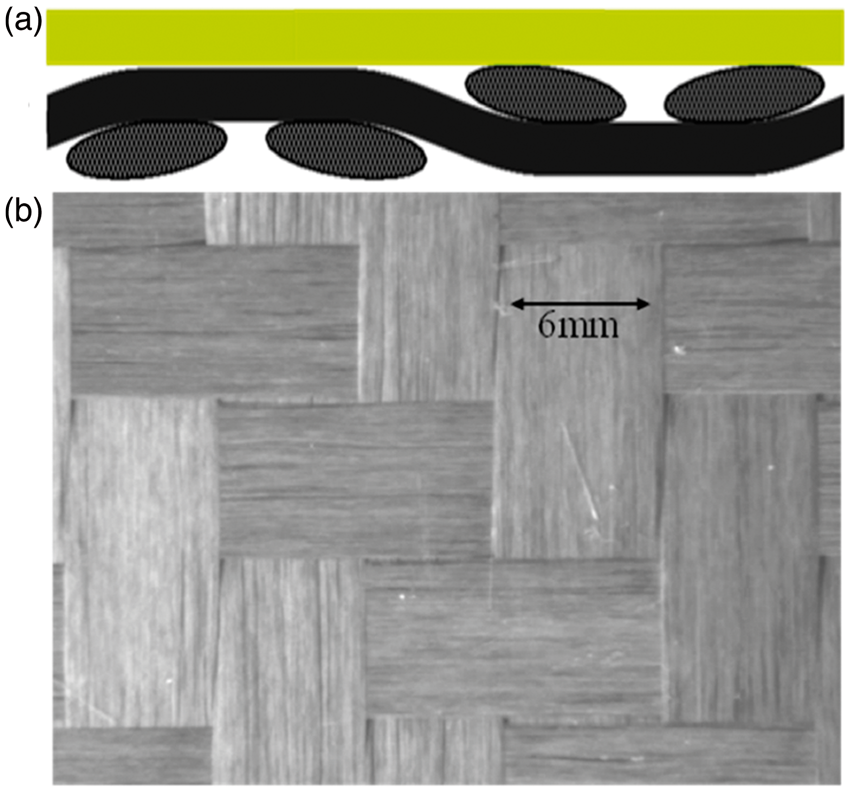
Experimental Setup
The in-situ flow visualization technique developed by Cender et al.
14
is adapted to visualize and record the resin flow and bubble motion. Figure 4 shows the flow visualization setup schematically.
14
The method consists of placing the prepreg dry side down, onto a clear and transparent acrylic table. Heat and pressure are applied to the prepreg in order to induce resin flow. From below the table, a CCD camera coupled with fluorescent lighting records the resin flow as it impregnates the dry fabric underneath along the table surface. The CCD camera is a Graftek Basler 1300, which records black and white images at 1626 × 1236 pixels resolution. A clear adhesive plastic film is laminated to the acrylic table surface to preserve the surface for reuse. The tests were performed at three different temperatures (50℃, 55℃, and 60℃) and three different pressures (15, 53, and 98 kPa). Note the process temperatures were chosen based on the prepreg manufacturers recommended process temperatures to induce resin flow.
Schematic of the experimental technique derived from Cender et al.
14
A bagging (or release) film is laminated to the resin film side of the prepreg sample – ensuring that air bubbles are trapped at the interface. The sample is then placed dry side down on a clear table where a CCD camera recorded the resin and bubble flow at the table surface, which is initiated with the application of pressure and temperature.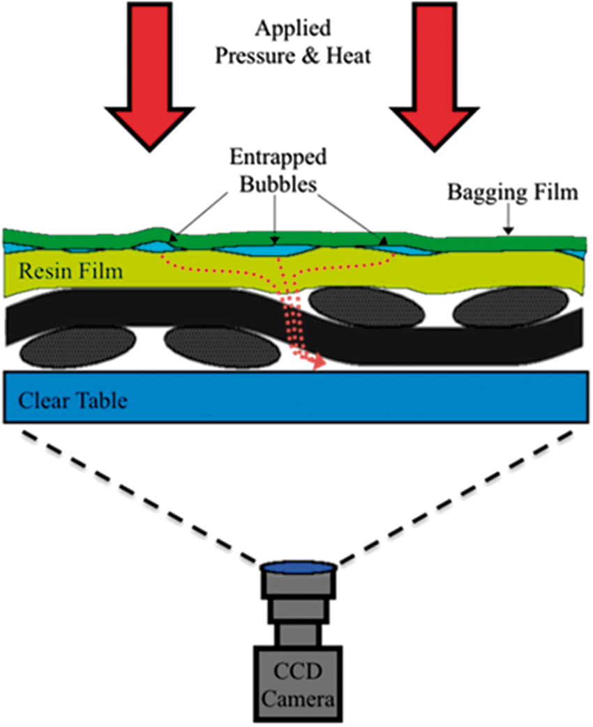
The lowest consolidation pressure used (15 kPa) simulates the effect of a tape placement compaction roller. Thus, the sample is not exposed to vacuum and air remains inside the air pathways. This is done by placing a heated compaction block of known temperature and weight on top of the sample. Samples were also tested under full (98 kPa) and partial (53 kPa) vacuum pressure by enveloping the prepreg sample inside a vacuum bag. The 15 kPa pressure includes the weight of the block (2 kPa), plus a weight placed on top of the block (13 kPa). The vacuum pressure tests (55, 98 kPa) include the vacuum pressure applied, plus the weight of the block (2 kPa). Heat was applied by placing the temperature controlled aluminum block on top of the sample. It is important to note that after the consolidation block is placed over the vacuum bag, it takes ∼1–2 min for the sample to reach a steady temperature, so these two tests cannot be considered isothermal. This is not an issue, as will be shown later: only the relative velocity of bubbles to resin velocity is of interest.
Each prepreg sample is prepared by laminating a release film to the resin film side of the prepreg (see Figure 4). In doing this, air bubbles become trapped between the release film and the resin, due to the irregular rough surface of the resin film, thus making poor intimate contact with the resin film. These trapped bubbles are later observed to flow with the resin down through the weave’s through-thickness gaps (called “pinholes”) and through inter-tow channels in the fabric along the table surface. Lighting and contrast are adjusted to obtain clear images of bubble boundaries. The high resolution of our CCD camera setup permits for clear flow visualization of features such as pinholes, inter-tow channels and resin/bubble interfaces.
Results
Figure 5 shows a micrograph of a polished 12-layer laminate of ST94-RC303T that was processed and cured with the supplier’s cure cycle. This laminate was prepared using the experimental setup described in the previous section under a vacuum bag and allowed to fully cure. The figure shows the presence of voids (i.e. very dark spots) present primarily outside the fiber tows in the inter-laminar spaces. Measurements of the inter-tow channel heights were taken from the micrographs and measured to be ∼80 ± 20 µm. The main goal of this work is to understand why the voids that become entrapped in the inter-laminar spaces between fiber tows are not able to be evacuated through the insides of dry fiber tows.
A 12-layer laminate of ST94-RC303T was processed and cured with the supplier’s cure cycle
18
from the experimental setup of this work under a vacuum bag. The inter tow channel dimension was measured (from polished cross-sections) to have a height dimension of ∼80 ± 20 µm.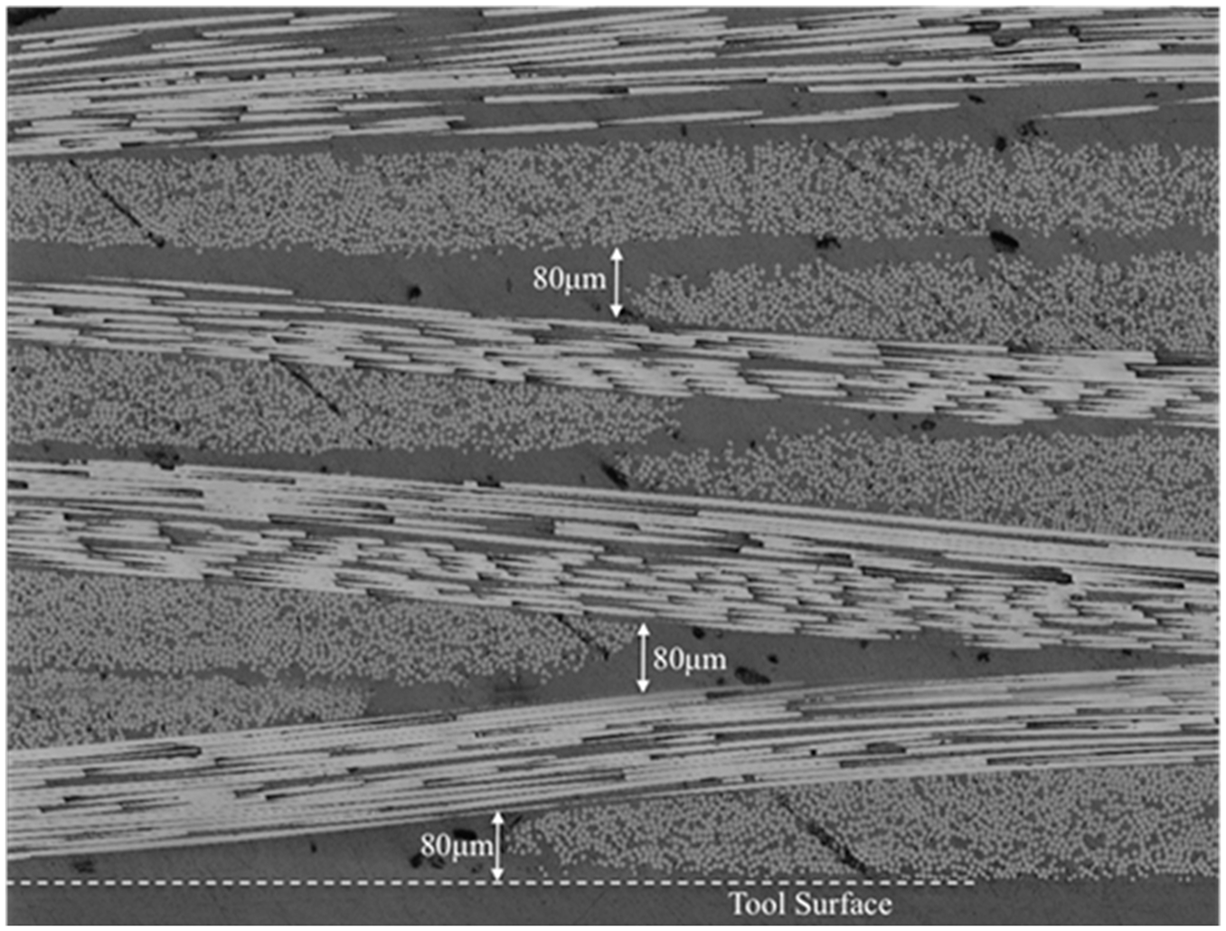
During the experiment, the pattern of resin flow is observed in detail.
14
Resin flows downward from the resin film through the pinholes in the fabric weave where there is a direct path for resin to reach the table surface. As shown in Figure 6, approximately 20 pinholes and 24 inter-tow channels are in the field of view. Once resin emerges from the pinholes, it proceeds to flow through the empty inter-tow channel in the fabric weave, where the domain is most permeable. Bubble interfaces are shown as white colored ellipsoids and are labeled in the figure.
Tracking of bubbles during resin saturation with 15 kPa of applied consolidation pressure at 50℃. (a) Bubbles emerge from pinholes in the fabric and moved through channels in between tows towards the resin flow front (6% resin impregnation), they can be evacuated if they reach the resin flow front before the inter-tow channel is saturated. (b) Bubble entrapped at tow boundary in inter-tow channel due to late emergence, when the resin impregnation (61% resin impregnation) is too far advanced into the tow.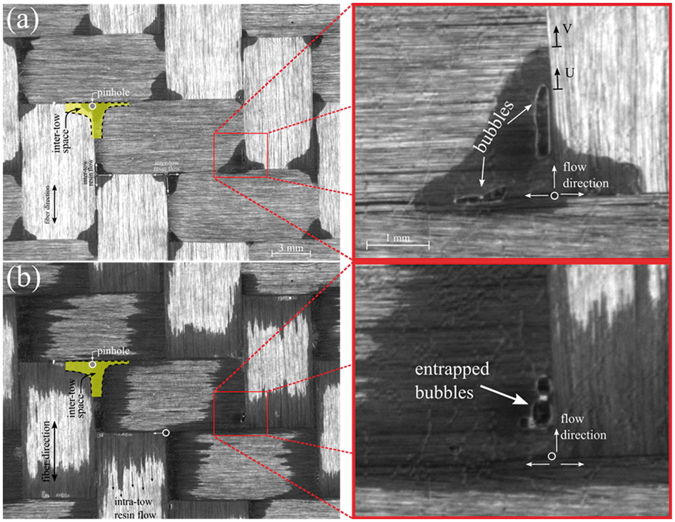
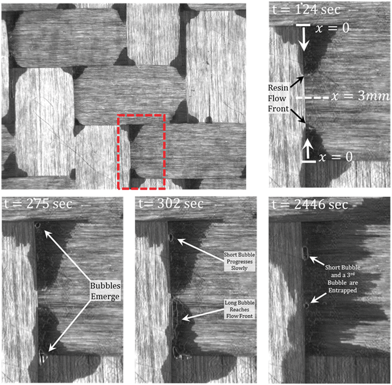
Figure 7, shows a time-lapsed set of images focusing on a single inter-tow channel saturating with resin. This figure shows how once inter-tow spaces are saturated, resin then proceeds to flow into fiber tows – predominately along the longitudinal fiber direction, due to the availability of dry fiber area being inside fiber tows and the only available vacuum pathway after inter-tow channels are fully saturated (see Figure 7 at t = 2446 s). With this method, the degree of resin impregnation is represented as the area filled with resin at the table surface. As this is occurring, bubbles in the resin film are observed to emerge through the pinholes with the resin and race through the inter-tow channels of the fabric in the direction of resin flow along inter-tow channels. Once the bubble emerges, some key observations are:
If the inter-tow channel is not saturated, a bubble will move faster than the resin, and may reach the resin flow front before the inter-tow channel is filled (see Figure 6(a)); Once the inter-channel is saturated, a bubble emerging from a pinhole will move along the inter-tow channel and stop at a spot equidistant between pinholes. If the advancing resin has not penetrated too far into the fiber tow, a bubble can occasionally squeeze into the fiber tow in longitudinal direction of the fibers; If the resin has advanced too far in the fiber tow, the bubble will remain lodged at the tow boundary (Figure 6(b)); Bubbles will not merge into fiber tows transverse to the fiber direction. Inter-tow filling with resin from two adjacent pinholes (Papp = 15 kPa, Pvac = 0 atm, T = 50℃). Two different sized bubbles appear at the same time. The large bubble from the lower pinhole quickly reaches the flow front and drains into the air pathway, while the small bubble from the upper pinhole does not reach the flow front before the channel is filled and remains entrapped at the tow boundary.
The implication of these observations is that initial degree of resin impregnation is a critical factor dictating if inter-laminar bubbles entrapped in the resin can migrate into air pathways. For example, prepregs consisting of a dry fiber layer between two resin films (i.e. Figure 1(b)) may entrap more bubbles during ply lamination and lead to less successful bubbles evacuations. This is due to the channels outside of fiber tows being already saturated with resin eliminate the opportunity to use these channels for bubble evacuation. Furthermore, the fact that bubbles are not observed to move into fiber tows though the transverse fiber direction suggests that unidirectional or non-crimp fabrics (i.e. with high resin impregnation) will be less successful at migrating bubbles into air pathways.
Figure 7 shows a time-lapsed set of images focusing on a single inter-tow channel saturating with resin. Resin is shown to progressively saturate the channel with time starting at t = 124 s with the appearance of resin flow fronts and dark contrast areas of resin. The resin flow fronts coalesce with each other at t = 302 s. Upon this coalescence, the resin proceeds to saturate the interior of the fiber tow. The resin velocity is greatly reduced due to the decreased permeability of the fiber tow with respect to the channel permeability as explored by Cender et al. 14 As the channel saturates, bubbles are observed to be introduced into the resin by the process of entrapped air underneath the vacuum bag as shown in Figure 4. One can observe at t = 275 s how bubbles first appear in view from the top and bottom of the channel. The bubble from the bottom is of much greater volume than the bubble from the top. With increasing time, the large bubble is able to coalesce with the resin flow front and disappears from view between t = 302 s and t = 2446 s. The smaller bubble (from the top pinhole) is not able to coalesce with a resin flow front as the channel becomes completely saturated. At t = 2446 s, the small bubble (lower) as well as a third bubble (upper) is shown to remain lodged within the inter-tow channel with the resin flow front saturating deep into the fiber tow.
Figure 8 shows a situation where entrapped air inside fiber tows is released into the resin inter-tow channel as a bubble. This test was performed with a consolidation block of 15 kPa at 55℃ without the use of vacuum. Without vacuum, a disproportionally large amount of air becomes entrapped within the small capillaries of fiber tows; however, this observation gives interesting insight into what happens when vacuum is not sufficiently applied for long enough time to remove the air inside fiber tows (i.e. vacuum dwell time). It is observed in Figure 8 that this can lead to a source of bubbles being released into the resin. Additionally, as the bubble reaches the nearest inter-tow channel, the bubble is stretched to the left and right. This bubble stretching behavior is undesirable, as it can initiate bubble breakup behavior. Gangloff et al.8,9,15 showed a correlation between bubble size and the relative bubble velocity with respect to the resin velocity – the larger the bubble, the greater its relative velocity with respect to the resin velocity.
Air entrapped at the center of a dry fiber tow can migrate to the inter-tow channel as the resin impregnation in the fiber tow advances.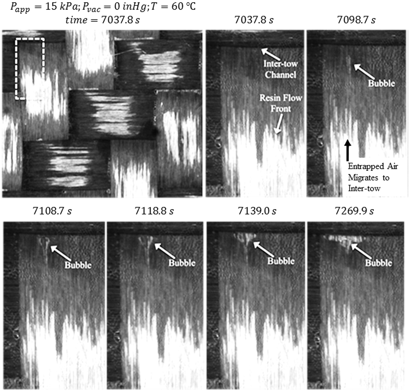
Discussion
Observed Bubble Mobility
It was shown in the previous section that bubbles are likely to become lodged at fiber tow boundaries in resin saturated inter-tow channels. It is more desirable to have bubbles meet the resin flow front before the channels are filled. This type of two-phase channel flow was experimentally and computationally modeled by Gangloff et al.8–10 The goal of this section is to correlate material and process conditions which must be met for entrapped bubbles to be vented from unsaturated inter-tow channels within the prepregs.
From the prepreg flow visualization experiments, 45 individual bubbles were tracked for quantitative analysis: five bubbles for each of the nine combinations of pressure (15, 53, 98 kPa) and temperature (50, 55, 60℃). Cases where the bubbles were able reach the resin flow front in an unsaturated inter-tow channel were exclusively selected. The movement of bubbles and resin emerging from pinholes is idealized as a 1D flow and they flow along inter-tow channels. The position of resin is tracked as it flows along the channel (i.e. distance from pinhole to flow front). The center position of bubbles, as well as their length (l = 2a) and width (w = 2b) were tracked over time (approximately 10 images per bubble), via interfacial measurements of contrast using the flow visualization technique described in Experimental Setup section. In each frame captured with the camera, five positions are located: (i) the location of pinhole (which does not move); (ii) the position of the resin flow front in the intertow channel in the direction of flow; (iii) the position of the front of the bubble (closest to the flow front); (iv) the length of the bubble along the direction of flow; and (v) the width of the maximum width of the bubble (transverse to the flow direction). These positions were located manually in each frame with ImageJ. The center position of bubbles was tracked by using the bubble length and their positions relative to resin flow fronts. Using the bubble front position and the bubble length, the bubble center position xc = xf − a/2 where “a” is the bubble length, xc is the center position, and xf is the front position. The bubble length and width are recorded in each frame, so the center position is accurate. Note, only bubbles that were ellipsoidal and had a measurable ellipsoidal radii (a and b) were tracked. Also, a and b are reported as averages over all of the frames. It was observed that the rate at which bubbles can race through the resin is strongly affected by bubble size and morphology. Bubble morphologies ranged from spherical (a/b = 1) to elongated (a/b ≫ 1).
To summarize, the unknowns from the prepreg flow visualization experiment related to bubble flow with respect to the resin flow are: local pressure/pressure gradient, channel geometry (height, width, shape), surface tension, resin film thickness around the bubble, approximate channel volume/cross-sectional area, fiber tow permeability (longitudinal and transverse), and dual-scale pore volume. The following were measured: bubble length and width, bubble velocity, resin front velocity, and resin viscosity.
The aim is to use the previous result from Cender et al. 14 to estimate the pressure gradient in the resin in order to determine the bubble velocity relative to the resin velocity. The model formulated in Cender et al. 14 characterizes the resin flow rate as the flow transitions from inter-tow filling to intra-tow impregnation by considering the change in pressure gradient across the tow boundary. As depicted in Figure 7, the resin flow rate in an inter-tow channel decreases dramatically once the flow front begins to advance into the fiber tow, owing to the fact that the resistance to flow is much greater inside the fiber tow (lower permeability).
Two-Phase Hele Shaw Flow
It was shown by Gangloff et al.8–10 that the relative motion of bubbles in viscous fluid as encountered in between fiber tows during composites processing can be sucessfully approximated with 1D channel flow. Previous studies on bubble transport in composites processing modeled the movement and formation of bubbles within fiber tows.1,5,7,9–13,15 The study presented in this paper focuses on the transport of bubbles through the interstitial space between fiber tows where external pressure drives the flow rather than surface tension (i.e. large Capillary number). Gangloff et al.
9
showed experimentally and computationally a Hele-Shaw modeling framework could be used to estimate the bubble and resin flow timescales through saturating micro-channels in Gangloff et al.
9
A two-phase Hele-Shaw flow schematic is shown in Figure 9.
A schematic of a two-phase Hele-Shaw model where a bubble suspended in viscous fluid (i.e. resin) is constrained to in-plane motion within a saturating micro-channel. This model can be used to approximate the bubble transport in prepreg inter-tow channels after Gangloff et al.
9
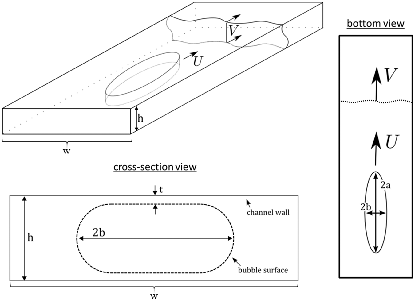
Note, Hele-Shaw flow is characterized to be viscous flow through a thin gap. A Hele-Shaw cell is rectangular channel where the channel height is much smaller than the width (h ≪ w). Equation (2) is the average fluid velocity in a Hele-Shaw cell,

Here, the average resin velocity is V the resin viscosity is μ, the channel height is h, and the pressure gradient in the resin is
Taylor and Saffman
19
studied the motion of a bubble in a Hele-Shaw cell using potential flow in elliptical coordinates. They find that the ratio of average relative bubble velocity to average resin velocity (U/V) is a function of the cell dimensions and the bubble dimensions. However, in the limit of very small bubbles they find that the relative velocity is,

Note that for spherical bubbles (a = b), the mobility will be
Capillary Number Theory
The classical problem of a long bubble flowing through a capillary tube was most notably studied by Bretherton.
20
The major result of this work was the discovery that the thin film of fluid with thickness tf, between the bubble and the capillary tube is,

Note the ratio U/V, as shown in equation (3), is called the “bubble mobility.”9,10,15 A bubble mobility greater than unity implies that the bubble is able to outrun the nearby resin flow front, coalesce, and escape the flow (i.e. Figure 7). A bubble mobility less than unity implies that the bubble is not able to reach the local resin flow front and there is a risk of entrapment. Bretherton found that the thin film thickness (tf) is a function of the Capillary number characterizing the flow. The rate at which the viscous fluid in front of the bubble is able to drain around the bubble and to the back of it provides the ability for the bubble to travel faster than the surrounding resin (i.e. Bretherton “lubrication” theory).
Maruvada and Park
21
build upon the Bretherton problem and the Saffman-Taylor problem by presenting a solution for a bubble translating in a Hele-Shaw cell with the inclusion of surface tension effects (i.e. small Ca),

Note, I is a constant defined in Maruvada and Park, 21 which accounts for the film thickness variation in the transverse direction and is a function of the bubble aspect ratio. For example, when the bubble is circular, I = 0.91. The bubble aspect ratio term is important, as it was observed in this work that bubble morphology plays an important role in the bubble mobility. The bubble aspect ratio controls the available surface area, for which incoming resin has to drain around within a micro-channel in order for a bubble to migrate through the channel. Increasing the surface area by bubble elongation provides increased resistance for resin to drain; however, a larger bubble also implies greater pressure gradient across the bubble via buoyancy. This work seeks to measure how the balance of buoyancy force versus surface tension force, based on the bubble aspect ratio, is experienced during the prepreg processing.
To further explore this, bubbles and resin flow fronts were measured as described earlier in Observed Bubble Mobility Section. Figure 10 shows an attempt to correlate the bubble mobility measurements with Maruvada and Park’s (Figure 10(a)) and Bretherton’s (Figure 10(b)) models. The results are plotted as functions of applied pressure and temperature. No obvious correlations were achieved with the Bretherton and Maruvada and Park models. This suggests that the Capillary number is not playing as strong of a role in the bubble mobility through the prepreg micro-channels. Also, no obvious trends were observed as functions of applied pressure or temperature on the bubble mobility. This suggests that the tuning of process parameters does not play as strong of a role in the bubble mobility during prepreg processing. Note, there is difficulty in measuring the bubble and resin velocities exactly, and flow visualization software was used to best approximate the position-time with margin of error.
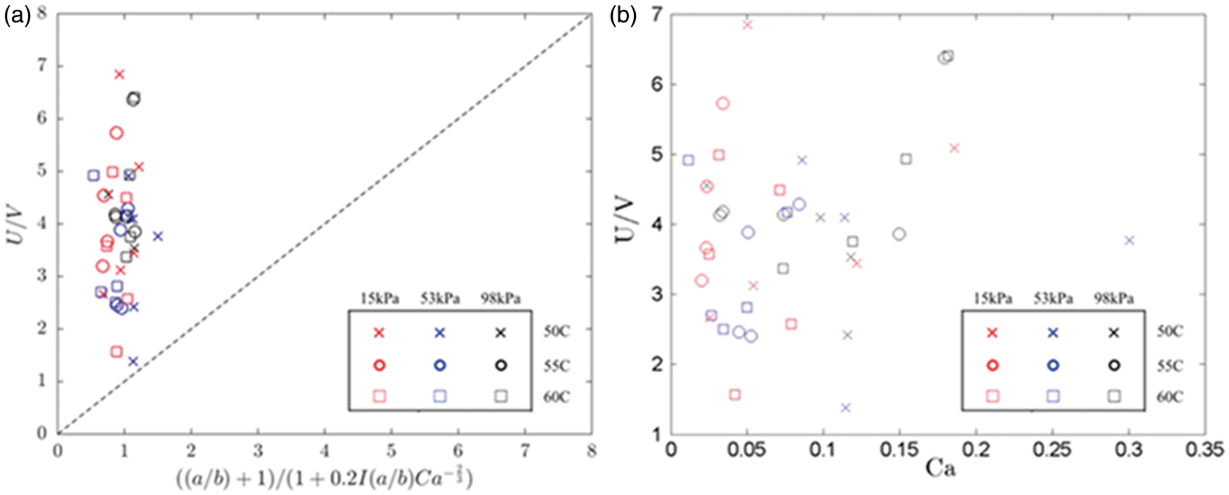
Given the lack of correlations found in Figure 10, equation (5) was reevaluated to attempt to find a better correlation. In the case of very large Capillary number, viscous forces are more dominate over surface tension forces. In this particular material, the resin viscosity is A plot of the bubble mobility model, based on work from Taylor and Saffman
19
with equation (3), versus experimental results. From the 45 bubbles which were tracked, U and V were measured directly. The bubble aspect ratio a/b was estimated based on the bubble length, 2a, and width, 2b, and channel depth, h. The channel dimension, h, was taken as 80 µm for each data point.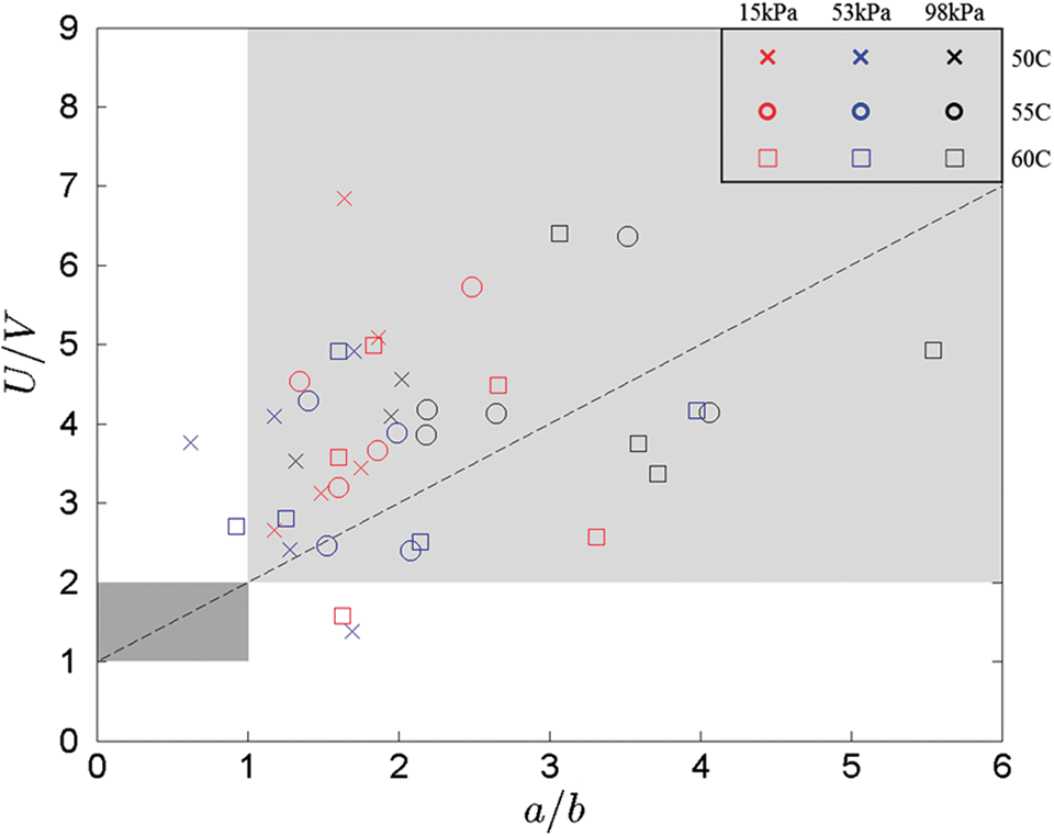
The physical implications of Figure 11 is that the bubble aspect ratio can be used to understand the balance of buoyancy force (i.e. scaling with bubble length) and surface tension force (scaling with bubble surface area), with the buoyancy force driving bubble flow and the surface tension force impeding resin drainage around the bubble and impeding its flow. The dotted line in Figure 11 represents the relationship from equation (3). From this, one can compare how the bubble mobility experimental data to the linear relationship between bubble mobility and the bubble aspect ratio from equation (3). The data points for different process conditions (pressure and temperature) do not show a trend in bubble mobility. The immense scatter in the data is expected since the model is only a first approximation and the channel (which varies and can not be measured) is appoximated as
Summary and conclusions
This work presents an experimental technique and a simple analytical model for characterizing the migration of bubbles, which are formed due to mechanical entrapment during layup, into air pathways during OOA processing. The role of the process parameters (i.e. applied pressure, temperature, and time) on the motion of bubbles during the advancing the degree of impregnation from the initial resin placement in partially impregnated prepregs was investigated. The presumption that bubbles can readily migrate into air pathways from the center of fiber tows is shown to be difficult, demonstrating that more void content in the final cured laminate may be due to entrapped air during layup than previously thought.
This study is a first attempt utilizing an in-situ visualization method to track bubble and resin together in partially impregnated prepreg systems. It is demonstrated here that bubbles move through the resin only when the resin is flowing. The physical mechanism which moves bubble towards air pathways is buoyancy. In order to impart buoyant force on a bubble, there must be a pressure gradient in the resin, and in order to induce a pressure gradient upon the application of pressure, resin must have an empty space to flow into. Thus, in order for bubbles to coalesce with a resin flow front, resin must be flowing through inter-tow micro-channels. Therefore, for partially impregnated prepregs, it is insufficient to simply apply vacuum at room temperature, where the resin does not flow. The simple model described here shows that the efficiency of evacuating bubbles from the laminate does not change with temperature or pressure and the experimental results have further validated this.
It was also demonstrated that the degree of resin impregnation in partially impregnated prepregs plays a critical role in the ability for bubbles to coalesce into air pathways. Higher resin impregnation is undesirable since bubbles cannot move into fiber tows once the resin has impregnated into fiber tows. Bubbles become stuck at fiber tow boundaries with insufficient pressure gradient to push them into tows. The bubble aspect ratio is found to be important in correlating the balance of bubble buoyancy and surface tension forces to the bubble mobility. Further investigations should consider the degree of resin impregnation by looking at alternate resin configurations during prepreg processing. Prepregs in which there is no dry area at the start of the process are inherently flawed in that they readily trap bubbles between plies, and the bubbles cannot migrate into air pathways inside the center of fiber tow cross-sections.
Footnotes
Acknowledgements
The authors would like to acknowledge and thank Prof Leonard W Schwartz of the University of Delaware for his advice and guidance throughout this work. Any opinions, findings, and conclusions or recommendations expressed in this material are those of the author(s) and do not necessarily reflect the views of ONR.
Declaration of Conflicting Interests
The author(s) declared no potential conflicts of interest with respect to the research, authorship, and/or publication of this article.
Funding
The author(s) disclosed receipt of the following financial support for the research, authorship, and/or publication of this article: The work was supported by the Office of Naval Research (ONR) under Grant Number N00014-10-1-0971. Additional support provided by the Scientific and Technical Research Council of Turkey (TUBITAK) for the 2219-International Postdoctoral Research Scholarship Program.