
Abstract
In this paper, the mechanical performance of resin transfer moulded nonwoven kenaf fibre/epoxy composites in the fibre volume fraction (V f ) range of 0–0.42 was investigated. The effect of the needle-punching direction on the tensile properties of the composites was also investigated. The highest tensile, flexural and fracture properties were attained at a V f of 0.42. The nonwoven kenaf fibre/epoxy composites were proven to exhibit tensile isotropy. The typical load versus displacement graph and scanning electron microscopy micrographs of the epoxy and nonwoven kenaf fibre/epoxy composites revealed that the energy absorbing events caused by the fibres led to improvements in the fracture toughness. Meanwhile, the micromechanical parameters of the composites were determined by a micromechanics analysis using the Cox–Krenchel model. The analysis proved the applicability of the model for nonwoven kenaf fibre/epoxy composites as the calculated efficiency factors were comparable to the values from previous literatures.
Introduction
There has been a rapid growth in the utilisation of natural fibres as a reinforcement or filler in composites.1–3 This is driven by the advantages they offer such as high specific strength and moduli, and a non-abrasive nature during processing.4–7 Natural fibres have also been proven to provide a greener, cheaper and viable replacement for conventional glass fibres. 8 The life cycle assessment (LCA) of glass fibre mats and flax fibre mats confirm that the production of the former requires a significantly higher amount of non-renewable energy as compared to the production of natural fibres. 9 Natural fibres provide lower environmental impacts as they are able to (1) reduce the amount of polluting base polymers, (2) lower the weight of composites, thus reducing fuel consumption when used in automotive applications, and (3) give out energy and carbon credits from their end-of-life incineration. 10
Natural fibres come in a variety of forms, and the nonwoven form produced by the needle-punching process has been utilised in numerous applications and possesses great potential as reinforcement in a composite. Motivated by environmental concerns, there is an increasing demand to fully exploit nonwoven natural fibres as reinforcement composites in the interior of automobiles. 11 Among the advantages of needle-punched nonwoven natural fibres are that they are lightweight, have excellent strength and good sound efficiency, are flexible and versatile, and have an attractive cost/performance ratio. 12 In addition, needle-punched nonwoven natural fibres have excellent z-directional properties that reduce delamination problems.11,12
Resin transfer moulding (RTM) is a suitable processing method for reinforcing thermosets with nonwoven natural fibres. This particular processing method retains the shape of the needle-punched nonwoven natural fibres, as well as produces a composite with better mechanical properties compared to other processing methods such as compression moulding and the hand lay-up method.3,13,14 Despite the advantages offered by nonwoven composites fabricated with RTM, there are still very limited studies directed at the mechanical properties of nonwoven kenaf fibre/epoxy (NKFE) composites.
The mechanical properties are essential and crucial as nearly all fabrication processes and most service conditions are exposed to some kind of mechanical loading. Basically, the mechanical properties of fibre-reinforced polymer composites are influenced by several factors such as the fibre volume fraction, fibre–matrix interaction, fibre aspect ratio and fibre orientation. 15 As the mechanical properties are a direct representation of the service performance of the composites, there is a need to better understand and quantify the micromechanical parameters which control the relationship between the structure and the properties of nonwoven reinforced thermoset composites. This can be done through a micromechanics analysis by utilising suitable models.
The modified rule of mixture by Cox–Krenchel16,17 is one of the widely used models due to its simplicity of usage. There have been several studies dedicated to determining the efficiency factor by using the Cox–Krenchel model for composites such as glass fibre/polyamide-66, 18 glass fibre/ABS, 19 bamboo/CP300, 20 hemp/PP 21 and stoneground wood fibre/PP. 22 Although this model is primarily used for composites with short fibres, several studies have utilised the model for randomly oriented fibres with lengths ranging from 10 to 50 mm.23,24 To date, studies on the determination of efficiency factors for NKFE composites by the Cox–Krenchel model have been little to none. Therefore, it is important to investigate the applicability of the aforementioned model for nonwoven natural fibre-reinforced thermoset composites by comparing the results of a micromechanics analysis with the theoretical values and the results from previous studies.
The aim of the present work was to study the mechanical behaviour of NKFE composites fabricated by using RTM. First, the physical and tensile properties of the kenaf fibres (KF) were characterised. Second, the effects of the fibre loading and needle-punching direction on the tensile properties of the NKFE composites were investigated. Third, the flexural properties of the composites at different fibre volume fractions were analysed and discussed. Then, the fracture toughness was characterised, and a morphological study was carried out on the fractured surface of the composites. Lastly, the micromechanics analysis of the tensile moduli at 0° and 90° to the needle-punching direction was carried using the Cox–Krenchel model.
Experimental
Materials
The needle-punched nonwoven KF mat with an areal density of 1100 g/m2 and stitching density of 50 cm−2 was supplied by Kenaf Natural Fibre Industries, Pulau Pinang, Malaysia. The average density of a single KF extracted from the nonwoven mat was 1400 kg/m3. The Bisphenol A epoxy resin (CP 210DF part A) and amine hardener (CP 210DF part B) used in the study were supplied by Camel Polymer Sdn. Bhd. The mixing ratio of the epoxy-hardener was 2:1, respectively.
Fibre length and diameter distribution
The distribution of the fibre lengths was characterised in accordance with the ISO 6989 Method A. Five hundred individual fibres were extracted from the nonwoven mat for the length distribution measurement. Meanwhile, the distribution of the fibre diameters was measured under an optical microscope (Olympus BX61 model). Two hundred individual fibre diameters were recorded.
Single fibre tensile testing
The tensile strength, σ
f
, and longitudinal tensile modulus, E
f1
of a single KF were measured according to the ASTM C 1557 standard by utilising the miniature tensile tester model LEX810 Dia-stron (UK) equipped with a laser diameter gauge (Mutitoyo Series 544 LSM-500S) and a load cell of 19.6 kN. The displacement speed of the upper clamp was set to 3 mm/min. Individual KF were secured onto a plastic mounting tab by using UV setting glue as shown in Figure 1. The tensile strength of 20 individual KF extracted from the nonwoven mat was measured. Prior to the test, the fibres were dried in a circulating oven at 60℃ for 4 h.
Fibre placement on plastic mounting tab for single fibre tensile testing.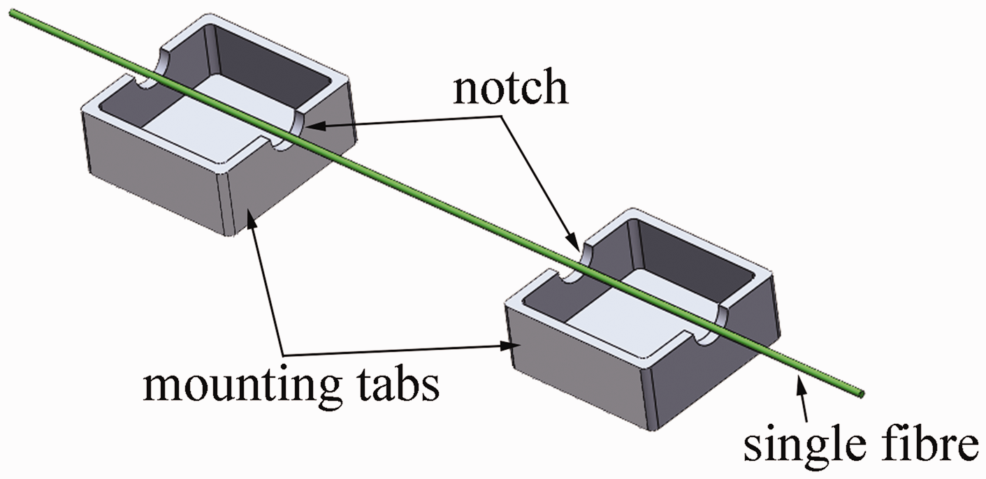
Preparation of composites
The NKFE composite laminates were fabricated using the resin transfer moulding (RTM) machine Hypaject MKV equipped with two reciprocating pumps. The ratio of the hardener to the epoxy resin was 1:2. Prior to the moulding, the nonwoven KF were cut into 600 × 300 mm2 dimension and dried at 60℃ for 4 h. Then, the dried nonwovens were placed accordingly on to the surface of the lower mould, followed by the placement of the upper mould on top of the lower mould as shown in Figure 2. It was then clamped tightly by using F-clamps to ensure no resin leakage during mould filling. The mixture was then injected into the mould containing different loadings of the nonwoven KF. After the mould was completely filled, the mixture was left to cure at room temperature for 24 h. After the mixture was fully cured, demoulding of the composite will be carried out. It was then cut into smaller test specimens by using a bandsaw followed by post-curing at 60℃ for 24 h.
Schematic representation of resin transfer moulding (RTM).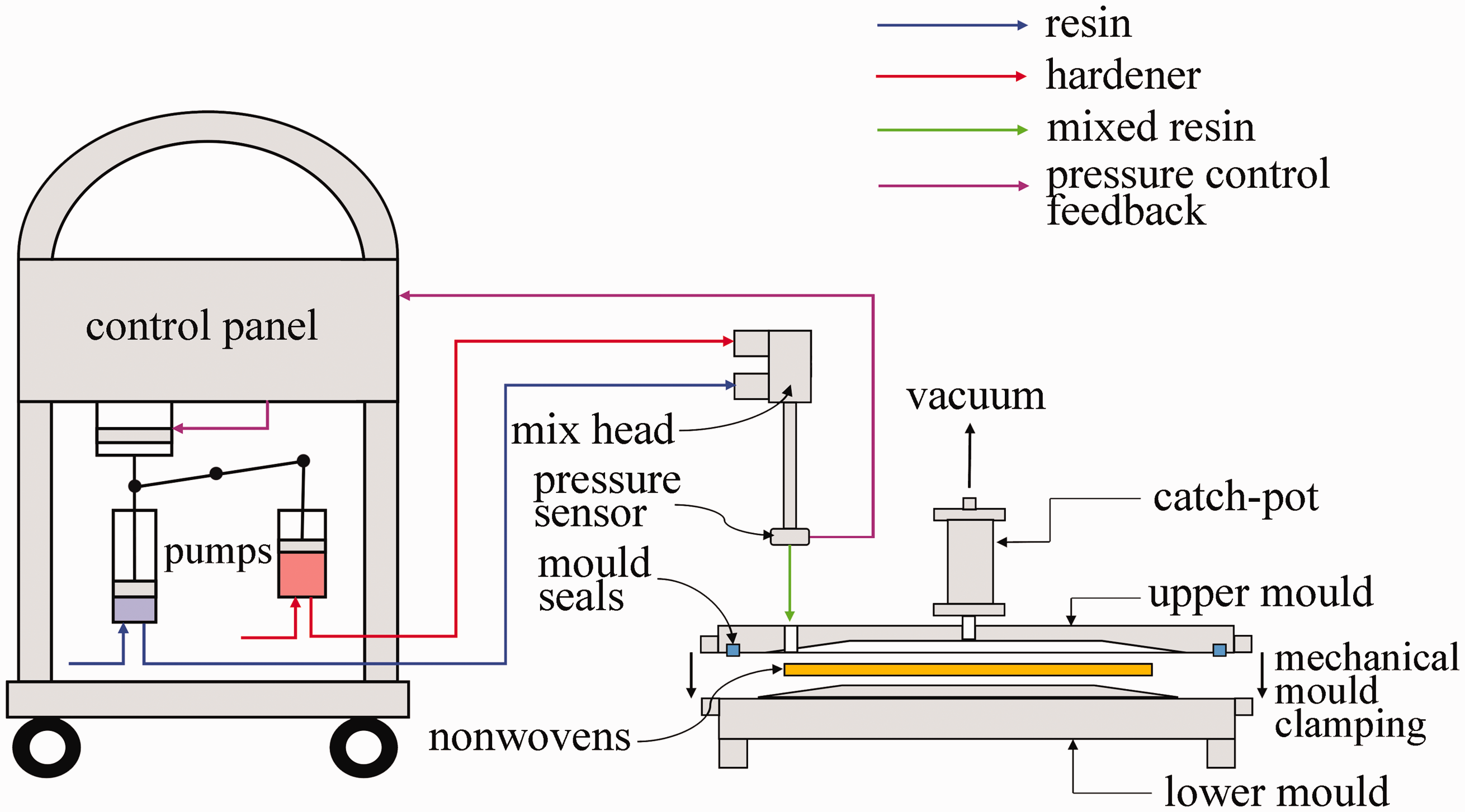
Tensile properties
The tensile strength and modulus of the NKFE were evaluated according to the ASTM D 3039 standard by using an INSTRON 5969 universal testing machine built in with an extensometer. The test machine was also equipped with a 50 kN load cell and operated at a rate of 2 mm/min. A total of at least five samples were tested with approximate dimensions of 20 × 200 × 9 mm3 for each needle-punching direction (0° and 90°), as shown in Figure 3.
Cutting directions of composites into tensile test samples.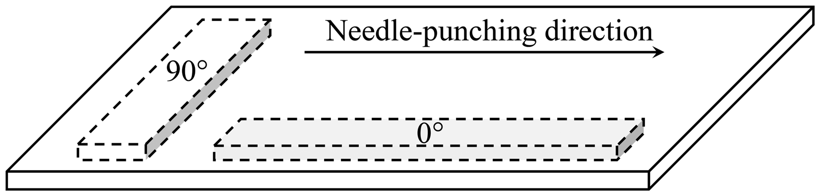
Flexural properties
For the flexural properties, three-point bend tests were also performed with an INSTRON 5969 universal testing machine in accordance with ASTM D 790. The approximate width, depth and length of the samples were 18, 8 and 160 mm, respectively. At least five samples for each fibre loading were tested at a crosshead speed of 5 mm/min and a span length of 130 mm.
Fracture toughness
The fracture toughness was determined using the single edge notch bending test (SEN3PB) in accordance with the ASTM D 2344 and also by using the INSTRON 5969 universal testing machine equipped with 50 kN load cell. The length (L), span length (S), width (W), and thickness (B) of the samples were 160, 60, 18, and 8 mm, respectively, which fulfilled the condition of 2B < W < 4B required by the aforementioned standard. A sharp pre-crack was generated in the notch by tapping a sharp razor blade, and its length (a) was then measured under an optical microscope. The samples were tested at a crosshead speed of 1 mm/min and the load–displacement curves were recorded. The maximum load upon fracture was then used to determine the fracture toughness, K
C
, which was defined as follows
25


Fracture surface morphology
Samples were first coated with a thin layer of gold by using the VG Microtech-Polaron Sputter Coater to render them electrically conductive. The fracture surface morphology of the composites was then observed using the SEM Carl Zeiss Leo Supra 50 VP model.
Results and discussion
Properties of single kenaf fibre
Figure 4(a) and (b) shows the length and diameter distribution of a single KF. The calculated mean length of the KF was 40.10 mm with a standard deviation of 17.40 mm. The standard deviation revealed a wide range between the maximum and minimum length. Figure 4 also shows the diameter distribution of a single KF. The calculated mean was 63.79 µm with a standard deviation of 37.37 µm. The calculated standard deviation indicated a large variation in the diameter of the KF, which is a common occurrence in natural fibres.
26
Therefore, the properties of the nonwoven KF/epoxy composites were consequently expected to have significant variations.
26
(a) Length distribution and (b) diameter distribution of single KF.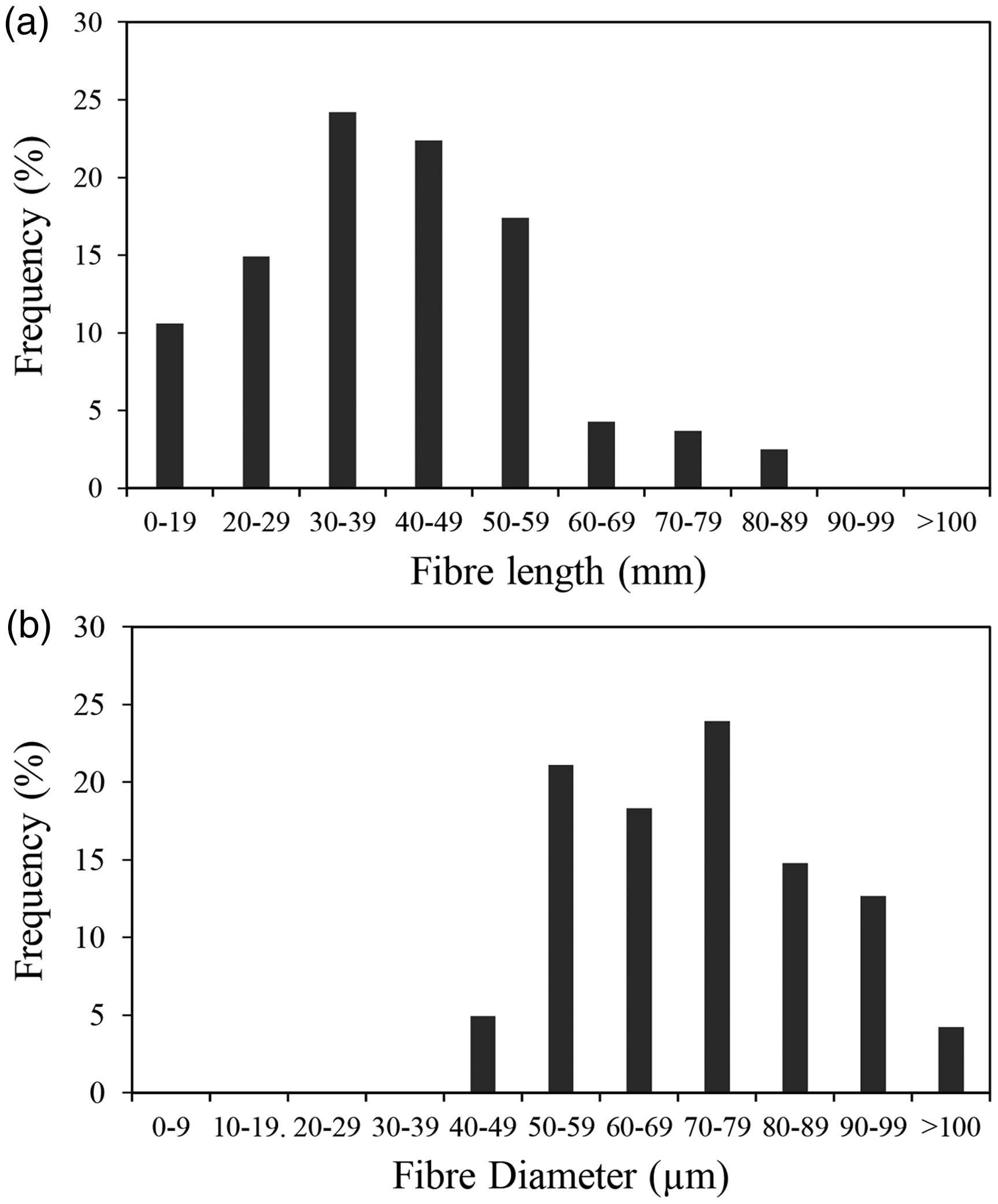
The average tensile strength σ f , and longitudinal tensile modulus E f1 of the single KF were 514.59 ±141.06 MPa and 26.06 ± 6.63 GPa, respectively. The standard deviations proved that both σ f and E f1 exhibited large variations. Such variations may be due to the assumption of fibre circular cross-section 27 and also the varied content of cellulose in the fibre, which is common in natural fibres.28,29 Nevertheless, the σ f and E f1 values obtained were still within the range of the experimental values presented in the previous literature.30,31 It is important to note that the section of the kenaf plant from which the fibres are extracted will have a significant effect on the properties of the composites. To optimize the mechanical properties of the single KF, the fibres should be taken from the section closest to the ground, and the bast fibres should be separated from the core.31,32
Tensile properties
In this study, the effects of fibre loading and the needle-punching direction on the tensile properties were investigated. Figure 5 represents the tensile strength and modulus of the neat epoxy and the NKFE composites at increasing V
f
of the samples at 0° and 90° to the needle-punching direction. Comparing the two needle-punching directions, the tensile properties generally displayed a similar trend. Also, at each V
f
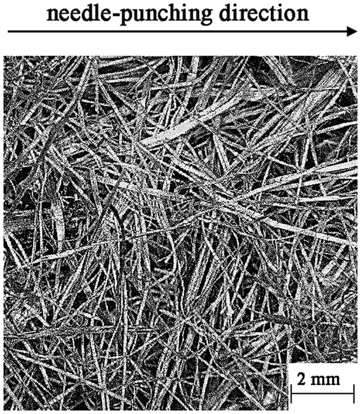
, the tensile properties of the composites at the two directions showed small differences. This indicates that the nonwoven KF mats exhibited tensile isotropy, as reflected in the tensile properties of the NKFE composites. Moreover, the tensile isotropy of the composites indicated that there was no preferential orientation in the nonwoven mat. This was verified by its microscope image, as shown in Figure 6, in which the KF in the nonwoven mat appeared to be orientated in all directions.
Tensile strength and modulus of epoxy and NKFE composites at different Vf and needle-punching directions. Optical microscope image of nonwoven KF.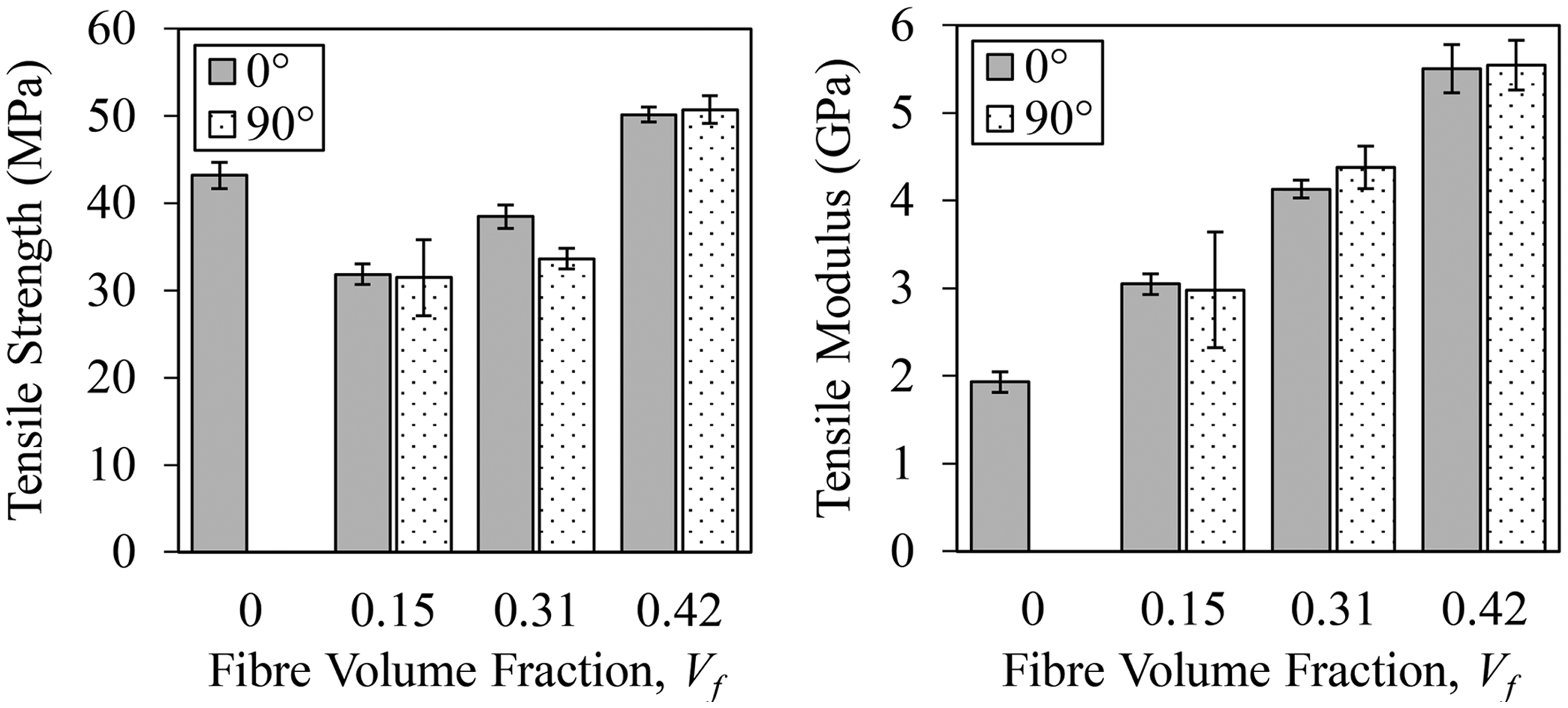
The composites at both needle-punching directions showed reductions in the tensile strength upon incorporation of 0.15 V f . At a low fibre loading, the nonwoven KF acted as flawed and the amount of fibres was not enough to impart and sustain a high strength in the matrix phase.33,34 A model by Kelly and Davies explained that the decrease in the tensile strength upon the incorporation of fibres occurs when the fibres have a lower failure strain compared to the matrix. Consequently, the composite failed at the strain level corresponding to the fibre tensile failure strain. 35 This premature failure occurred especially at a lower fibre loading when the V f was smaller than the critical fibre volume fraction, V crit , as explained by Gibson. 36
The random orientation of the KF also contributed to the decrease in tensile strength. Some parts of the fibres were perpendicularly oriented to the loading direction, thus acting as a potential defect. 37 Sreekala et al. also found that using fibres with a length of ∼40 mm will induce fibre curling, which will then reduce the fibre length, and consequently reduce the effective stress transfer. 38 This was also worsened by the poor interaction between the hydrophilic KF and the hydrophobic epoxy. Nevertheless, as the fibre volume fraction of the nonwoven KF increased, the properties of the fibre phase became more dominant, and consequently, the tensile strength of the composite improved. The highest tensile strength was achieved at 0.42 V f for both composites at 0° and 90° to the needle-punching direction.
Meanwhile, the tensile moduli at both needle-punching directions increased linearly upon the addition of the nonwoven KF, with the highest being achieved at 0.42 V
f
. This improvement was due to the nature of the KF itself. The addition of a fibre that possesses a higher modulus than the polymer matrix will inhibit the movement of the polymer chain. Consequently, the stiffness of the resulting composites was improved. These values were also higher than those reported in previous studies in which hot compression was used to form the nonwoven KF.
39
This implies that the formation of a nonwoven mat through the needle-punching process might produce composites with a better tensile modulus compared to the formation of nonwoven by hot compression. This could be due to the hollow cylinders of the needle path, as shown in Figure 7(a), produced by the needle-punching process, which aid in the penetration of the resin into the fibre mat.
40
This induced a lower void content (∼5%) in the composites, which has been reported in our previous study,
41
as compared to the void content (∼8%) reported by Fiore et al.
39
This may have been responsible for the superior tensile modulus. In addition, the mechanical fibre interlocking within the nonwoven KF shown in Figure 7(b) might be responsible for the enhancement of the tensile properties of the composites as it promotes a more efficient stress transfer between the fibres.40,42
(a) Needle path in nonwoven KF produced by needle-punching and (b) cross section of nonwoven KF showing the mechanical fibre interlocking.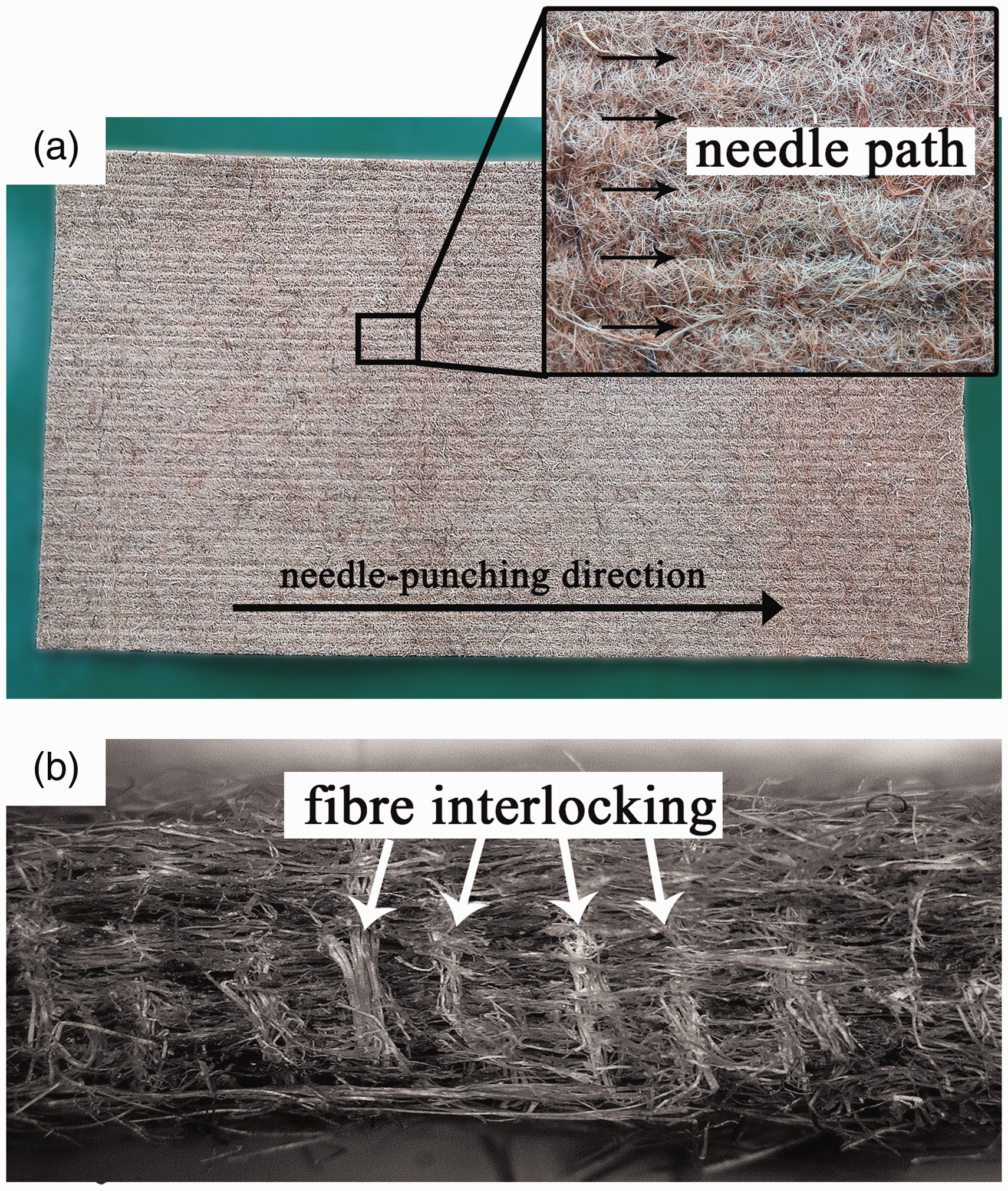
Flexural properties
Figure 8 shows the flexural properties of the epoxy and NKFE composites at different V
f
. Both the flexural strength and modulus at 0° of the needle-punching direction showed a similar trend to that of the tensile properties. The flexural strength dropped after the incorporation of 0.15 V
f
of nonwoven KF. Similar to the tensile strength, the decrease in the flexural strength may have been due to the low loading of the nonwoven mat, which consequently acted as flaws in the composites. The reduction in strength could also be attributed to the random orientation of the fibre, fibre curling and poor fibre–matrix interaction. An increment followed soon after the strength reduction, with the highest being attained at 0.42 V
f
; an increase of 6% from the flexural strength of the neat epoxy. It could also be seen that the incorporation of 0.15 and 0.31 V
f
improved the flexural modulus by 27% and 69%, respectively. The highest flexural modulus was achieved at 0.42 V
f
with an improvement of more than 120% from the flexural modulus of the neat epoxy. The improvements in the flexural modulus were also due to the stiffness of the KF.
Flexural strength and modulus of epoxy and NKFE composites at different Vf.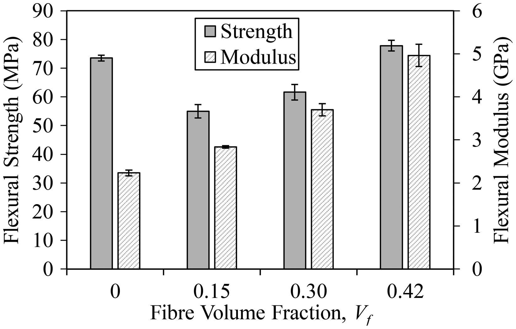
Fracture toughness
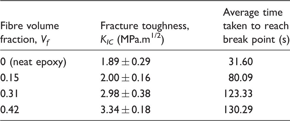
Table 1 and Figure 9 display the effects of the V
f
on the fracture toughness and the typical force–displacement plot of the neat epoxy and NKFE composites, respectively. The fracture toughness of the neat epoxy was still within the range of what was reported in previous studies.
43
The fracture toughness of the NKFE composites increased as the V
f
of the nonwoven KF increased. A similar trend was also reported by Hughes et al., whereby the fracture toughness of hemp and jute/polyester composites increased as the V
f
increased.
44
The highest fracture toughness was attained at 0.42 V
f
with an improvement of 77% over the neat epoxy.
Typical load versus displacement curve of epoxy and NKFE composites at different Vf (arrows are showing “pop-in”). Fracture toughness of epoxy and NKFE composites and the average time taken to reach break point.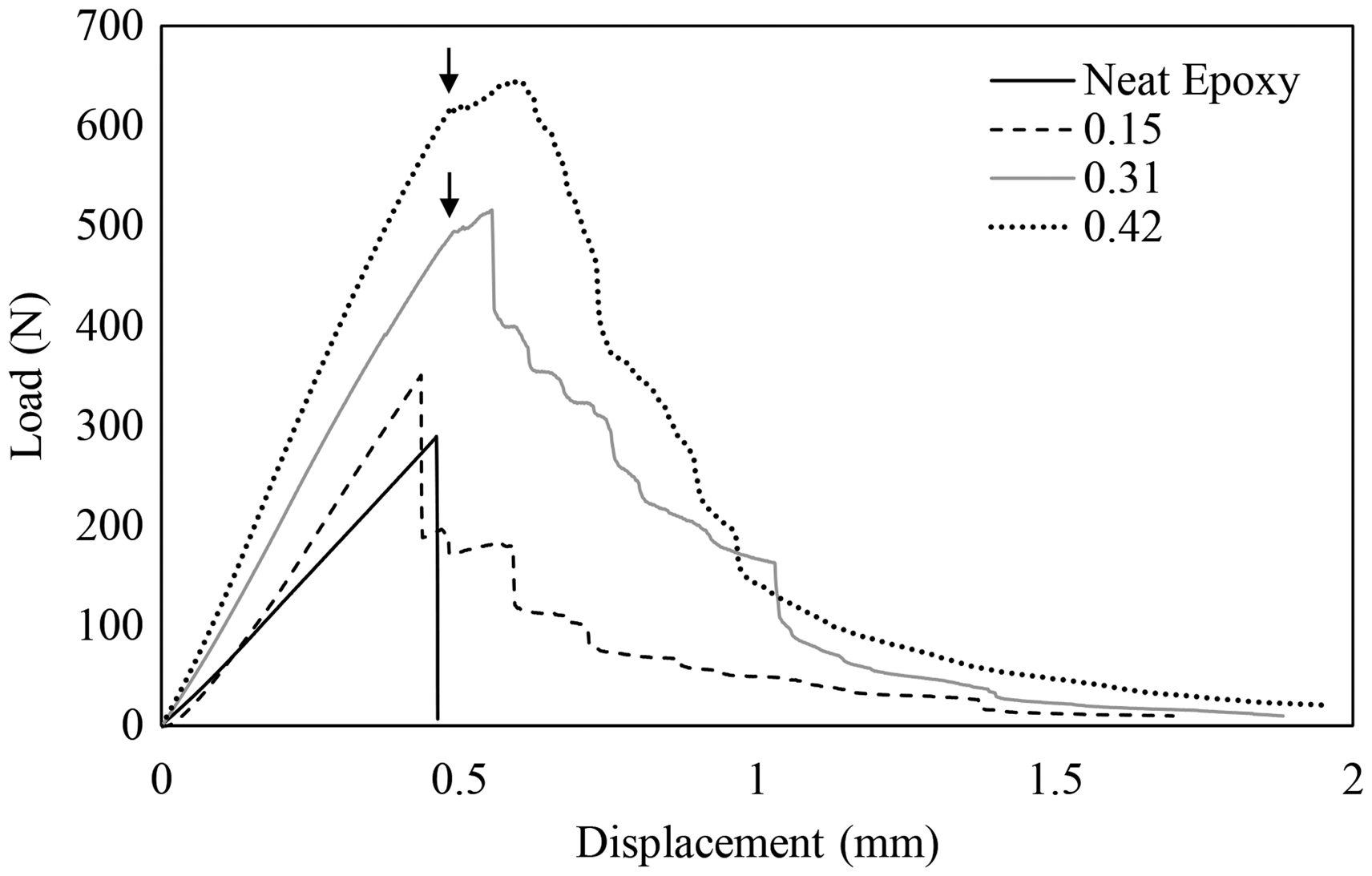
The toughness of the neat epoxy was due to the energy dissipation mechanism by plastic deformation.
45
This mechanism was hindered when the nonwoven KF was added. Instead, the fracture toughness of the composites was attributed to energy-absorbing events such as fibre pull-outs, fibre fracture and fibre-bridging, as shown in the SEM micrographs in Figure 10 (discussed later).46,47 Fibre-bridging, in particular, might be improved by the interlocking of mechanical fibres within the nonwoven KF. Therefore, the addition of more nonwoven KF resulted in greater energy absorption, which consequently led to an increase in the K
IC
of the NKFE composites.
48
Fracture surface morphology of (a) epoxy and NKFE composites at (b) 0.15 Vf (c) 0.31 Vf and (d) 0.42 Vf of nonwoven KF.
From Figure 9, it can be seen that the load versus displacement curves of the neat epoxy and its composites were typical of elastic/stiff materials. For the neat epoxy, a sharp drop in the load occurred immediately after the break point, while all the composites at every V f displayed extensive and stable crack growth. Due to the relatively low tenacity of the matrix phase, the crack growth was locally accelerated in the resin-rich area. Meanwhile, in the fibre-rich area, the reinforcement acted as an obstacle that caused the deflection of the crack, which in turn reduced the velocity of the crack propagation and produced a tortuous crack path. The average time taken for the composites to completely break down, as shown in Table 1, further validated the aforementioned statement.
A small drop in the load before the maximum load point was also observed for the composites with 0.31 and 0.42 V f , which indicated a “pop-in” (pointed by the arrows in Figure 9). The cause has yet to be fully understood; however, Karger-Kocsis et al. associated this phenomenon with crack bifurcation, which occurs after the sudden deviation of a crack from the preferred path in the case of PP/glass fibre composites. 49 Fibre orientation is one of the factors that may have an influence on crack bifurcation. A study by Romhány et al. 50 stated that a pop-in, which is associated with crack bifurcation, also indicates poor consolidation of the composites. As mentioned earlier, the pop-in was only observed in composites with 0.31 and 0.42 V f . Therefore, it can be assumed that the consolidation quality of the composite was poorer at higher Vf, and this was due to the higher resistance for the resin to penetrate easily into the nonwoven mat.
Fracture surface morphology
The SEM micrographs of the neat epoxy and its composites are shown in Figure 10(a) to (d). The SEM micrographs revealed that the fracture surface of the neat epoxy was smooth with striated lines indicating extensive plastic deformation. This further proved that the crack propagation was rapid, as mentioned earlier. Meanwhile, the SEM micrographs of the NKFE composites showed a rough fracture surface. The nonwoven KF provided bridges in the crack that dampened or slowed down the crack propagation in the composites. The micrographs of composites also showed extensive fibre pull-out. In addition, circular and longitudinal voids, which were produced from the fibre debonding, could also be seen. Both were more visible at higher V f . Besides the fibre pull-out, plastic deformation could be observed at the matrix region, which was also developed during the fracture event. Figure 10 also shows that the fibre pull-outs were more prominent at the fracture surface of the composites at different fibre loading, as compared to the fibre breakage. This may have been due to the poor adhesion between the hydrophilic nonwoven KF and the hydrophobic epoxy matrix.
Micromechanics analysis
As mentioned earlier, a micromechanics analysis allows the quantification of the parameters which control the structure–property relationships of the natural fibre-nonwoven/thermoset composites. However, no micromechanical model was developed specifically for the composites with the needle-punched nonwoven mat, which was made up of a loose matting structure with fibre mechanical interlocking and hollow cylinders. It was proven in the previous section that the NKFE composites exhibited tensile isotropy. Thus, the micromechanical model meant for randomly oriented fibres could be used for the micromechanics analysis. In this paper, the micromechanics analysis was based on the modified rule of mixture developed by Cox
16
and Krenchel,
17
which was performed on the composites at 0° and 90° to the needle-punching direction. The modified rule of mixture was defined as

The experimental data for the tensile moduli of the NKFE composites at both needle-punching directions from 0 to 0.42 V
f
of the nonwoven KF reinforcement displayed increasing trends (see Figure 5). This was consistent with the modified rule of mixture. The moduli in Figure 5 could be modelled by rearranging the modified rule of mixture equation

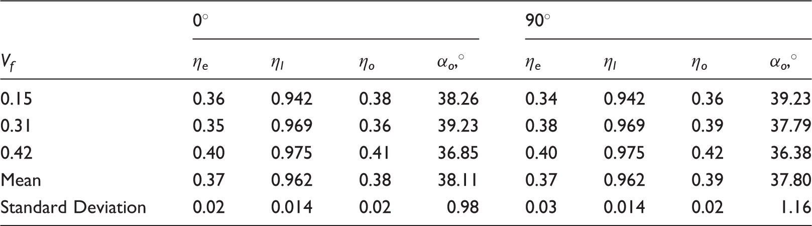
Figure 11 shows the best regression line of the tensile modulus of the composites according to equation (4). From the best regression line, it was possible to calculate the η
e
for the moduli of the composites at both needle-punching directions. For the composites at 0° to the needle-punching direction, the mean value of η
e
was 0.37 with a standard deviation of 0.02. Meanwhile, at 90° to the needle-punching direction, the mean value of η
e
was 0.37 with a standard deviation of 0.03.
Tensile modulus at different needle-punching directions against Vf.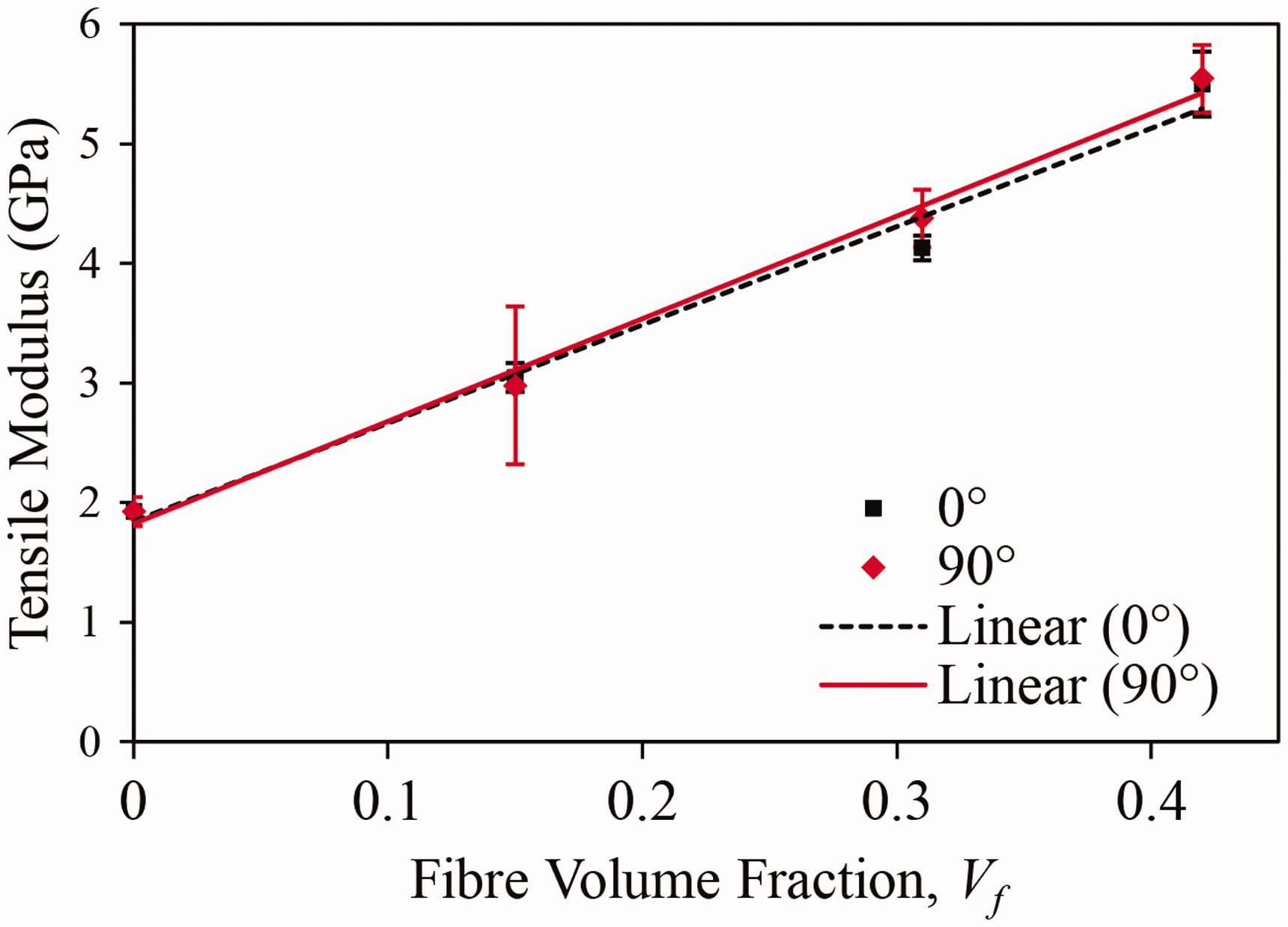
The efficiency factor η
e
was also defined as the product of the orientation factor (η
o
) and the length factor (η
l
)

The Cox shear-lag theory defined the length efficiency factor η
l
as
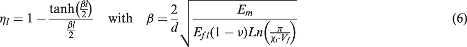
In equation (6), β is the coefficient of the stress concentration rate at the end of the fibre, l is the fibre length, d is the diameter of the fibre and v is the Poisson's ratio of the composite at a particular V f . In this study, the fibres were assumed to be packed in a square arrangement, thus χ i = 4. 51 Equation (6) gives the calculation of η l . The calculated mean of η l for the composites at both needle punching-directions was 0.962 with a standard deviation of 0.014. This was close to the values reported in previous studies, where η l was in the range of 0.89 to 0.91.21,22,52
From here, the orientation factor η
o
was calculated using equation (5). It was 0.38 ± 0.02 and 0.39 ± 0.02 for the composites at 0° and 90° to the needle-punching direction, respectively. Both were very close to the results reported in previous studies in which η
o
was equal to 0.375
24
and 0.452
53
for randomly oriented fibre and needle-punched fibre, respectively. According to Krenchel,
17
the orientation factor can be computed by using the equation below

Calculated efficiency factors and fibre orientation limit angles under tensile mode for samples 0° and 90° to the needle-punching direction.
Conclusion
In this investigation, the incorporation of nonwoven KF basically improved the tensile and flexural properties alongside the fracture toughness of the NKFE composites, with the highest values being attained at 0.42 V f . The high modulus of the KF and the mechanical interlocking of nonwoven KF were responsible for improvements in the modulus. Meanwhile, the SEM micrographs of the epoxy and its composites revealed that the energy-absorbing events caused by the KF led to improvements in the fracture toughness. The crack propagation in the neat epoxy was rapid, indicating catastrophic failure, while the crack propagation in the composites occurred at a much slower and gradual rate.
The study of the effect of the needle-punching direction revealed that the NKFE composites exhibited tensile isotropy. This was due to the non-preferential orientation in the nonwoven KF, which validated that it was randomly oriented. The tensile isotropy of the composites was also verified through a micromechanical analysis using the Cox–Krenchel model. The analysis enabled the length and orientation efficiency factors as well as the fibre orientation limit angle for composites at different needle-punching directions and V f values to be determined. The applicability of the Cox–Krenchel model in the micromechanics analysis of the NKFE composites was validated as the calculated efficiency factors were comparable to the values from previous literature. Meanwhile, the fibre loading showed no significant effect on the efficiency factors of the composites.
Footnotes
Declaration of Conflicting Interests
The author(s) declared no potential conflicts of interest with respect to the research, authorship, and/or publication of this article.
Funding
The author(s) disclosed receipt of the following financial support for the research, authorship, and/or publication of this article: The authors would like to appreciate the financial support given by Universiti Sains Malaysia and the Ministry of Higher Education, Malaysia for providing RUC Grant (grant no. 231/PKT/8640012) and LRGS Grant (grant no. 203/PKT/6725002), respectively.