
Abstract
Wound composite structures such as hyperbaric hydrogen tanks may experience accidental situations, for example in case of a fire. The FCH-JU project FireComp aims at better characterizing the conditions that need to be achieved in order to avoid a failure of a composite pressure vessel. This research program involves specific experiments to improve the understanding of loss of strength of composite high-pressure vessels in fire conditions. The present study investigates the effect of a coupled thermomechanical loading (cone calorimeter exposure and, simultaneously, mechanical stress) on the residual strength of a composite material. A specific device combining a cone and a four-point bending bench has been designed. The influence of the coupled aggression is addressed by comparing the temperature on the front and the rear sides, the mass loss, and the residual tensile strength of a set of samples subjected to a heat flux only and a set subjected to a heat flux and a four-point bending. The results do not exhibit a clear effect of the mechanical load: the thermomechanical properties of both sets of samples are similar.
Keywords
Introduction
Thanks to their remarkable ratio mass/stiffness/strength, carbon/epoxy composites are widespread in many areas, including aerospace, automobile, marine, military, etc.1–4 The extensive use of these materials raises the question of their safety such as, for example, the damage tolerance after impact or the fire resistance. As it needs to tackle the field of multiphysical couplings, this latter type of aggression is a complex problem that requires thorough understanding of the decomposition mechanisms of the materials5,6 and of the interaction between components and the temperature gradients formed during typical fire conditions.7,8 This problem is particularly crucial when considering structures undergoing simultaneously a mechanical load and a flame, as for example hydrogen pressure vessels (manufactured by composite filament winding) subjected to a fire. The mechanical properties of the composite depend on the state of the polymer matrix, the reinforcing fibers but also on the bonding between the fibers and the polymer. These properties are all highly temperature dependent.9–11
When a composite material is subjected to high heat fluxes (e.g. a fire), it undergoes a thermal degradation leading to gaseous emissions (volatilization) and the initiation and growth of a “char” layer, whose mechanical properties are lower than those of the virgin material. Works12–14 can be found in the literature highlighting the role of the charring process in the mechanical weakening of the composite material at different scales: the sample scale representative of the load-bearing structures (this scale can provide valuable information for computational structure purposes), the representative volume element (a few mm3), 15 or the component (fiber) scale. 16 An increasing incident flux leads to a thicker char layer and a sharper drop of the mechanical strength. The literature also addresses the effect of the mechanical damage on the heat transfers. 17
Some works clearly identify the pivotal role played by the brought thermal energy to the solid fuel.12,14,15 However, these results have been obtained by submitting a composite sample to an incident heat flux, without mechanical load (except Elmughrabi et al.
18
which studies the effect of a tension/compression stress on heat release rate), whereas in-service structures support stresses. In this context, the European FCH-JU Project FireComp
19
aims at proposing a specific approach for gaseous hydrogen storage system design (hyperbaric tanks made by prepreg filament winding) subjected to fire. It is nowadays an accepted fact that correct lifetime predictions need to understand more precisely the material behavior, its physical properties, and the degradation mechanisms that lead to fracture in in-service conditions, which means an accidental exposure to a given heat flux (fire) and a mechanical load (inner pressure). Previous projects20,21 have proved the influence of the temperature on the mechanical behavior of the storage between −40 and 85℃, representing the temperature range of use (from emptying up to filling): the temperature gradient leads to an important modification of the stress distribution within the composite structure. The FireComp project thus takes into account an additional difficulty with respect to the aforementioned works, since it deals with coupling between the mechanical loading, temperature, and fire aggression: the outer layers are directly exposed to the fire and mechanical stresses state and the resin is consequently degraded. Those chemical reactions (volatilization and char formation), which can be mechanically considered as a type of damage, substantially modify the stress distribution within the structure. In order to investigate the role of a mechanical stress on the charring kinetics, a specific device (presented in “Experimental setup coupling mechanical load and heat flux” section) combining a cone calorimeter and a bending creep bench has been developed. Since the fiber orientation in composite materials influences the mechanical strength, three sets of samples (“Composite material and coupled tests” section) cut in tanks made of different stacking sequences (hoop, ±45°, and quasi-isotropic) have been tested thanks to this setup: for each orientation, reference samples are subjected to different incident heat flux values (cone calorimeter) without mechanical load, whereas a second batch is subjected to the same thermal conditions and an additional constant bending load. The influence of the mechanical load during the fire exposure is investigated by comparing three experimental sets of results:
Temperature: During the fire exposure, the evolution of the surface temperature is recorded by thermocouples (on the front and the back side) and an infrared camera (on the front side). Mass loss: Each sample is weighed before and after test. The mass loss is a macroscopic evidence for the damage state. Mechanical strength: After fire exposure (with or without mechanical load) and cooling, each sample is subject to tension up to fracture. The mechanical strength is recorded and the influence of the test conditions analyzed.
Experimental setup coupling mechanical load and heat flux
The investigation of the role of a mechanical load on the charring process has needed the development of a specific setup. The aim is to expose a composite sample to a controlled thermal flux while applying (or not) a constant mechanical load. The experimental setup has to meet some requirements to be adaptable to different types of sample geometry. For the sake of safety when the specimen ignites and burns, the gaseous emissions have to be kept and extracted by a large hood covering the device. The mechanical device has to be protected from the hot gas flux and from the fire.
These conditions prevent from using usual tension machines. That is the reason why it is necessary to develop a specific, simple, reliable, and multipurpose setup. The adaptation of a three- or four-point bending creep bench has been found to be a tractable solution (Figure 1): thanks to rail guides, the mechanical bench can be positioned in front of a heat source (a burner, a cone calorimeter, or a radiant panel). The samples of this study have all been subjected to a cone calorimeter apparatus. By the means of a jack, it is possible to impose a constant displacement (and measure load evolution) or, conversely, a constant force (and measure the displacement evolution). One may choose to expose to the cone the sample side under compression or tension. The characteristics of the device are the following:
The maximum dimensions of the samples are width 50 mm and length 300 mm. The usual maximum thickness is 5 mm but specific grips can be machined for thicker samples. The maximum mechanical load is 2.5 kN and the maximum actuator stroke is 150 mm. The maximum distance between supports is 275 mm for three-point bending and 80 mm for four-point bending. Overview of the coupled setup (a); zoom of the sample subjected to four-point bending and to cone calorimeter (b); and schematization, configuration “compression side in front cone” (c).
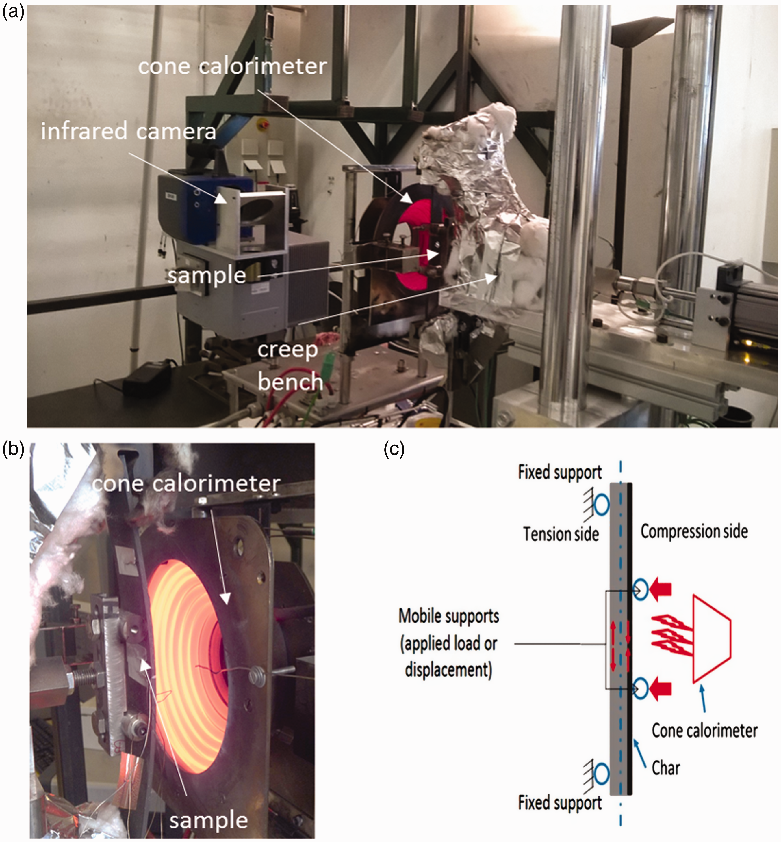
All tests are multi-instrumented by thermocouples and an infrared camera. The thermocouples have been put on both sides (in the center) of the sample to measure the evolution of the temperatures during the test. An infrared camera is used to observe the sample surface exposed to the radiative flux through the aperture of the cone calorimeter. The observed area is focused on the center of the sample and is approximately 25 mm wide and 60 mm long. A postprocessing step may then lead to the identification of the surface temperature and provides a temperature distribution at the surface, which completes the local measurements given by the thermocouples. Possible heterogeneities or changes may then be checked as a function of time and for various mechanical loads.
A coupled test comprises the following steps:
The samples are prepared; in particular, thermocouples are stuck on both sides (the side exposed to the thermal aggression and the back side of the composite sample). They are then put on the supports of the creep bench. A deflection or a load is applied to the sample. The creep bench is shifted in front of the heat source and the sample is exposed as long as needed. Since the flux is imposed, the prescribed duration corresponds to a given brought thermal energy. The creep bench is shifted back and the cone is shut down.
Composite material and coupled tests
Tests have been performed on composite samples cut in cylinders manufactured in the same way as the hydrogen hyperbaric tanks. The material is composed of T700S carbon fibers (a widely use fiber in composite structures for aircraft, ship, civil infrastructures) in an epoxy matrix. Parallelepipedic specimens of dimensions 300 mm × 25 mm are cut in large wound cylinders (whose diameter is 1.1 m and length 11.6 m). For each stacking sequence studied, a corresponding cylinder is wound on a liner, then cured, cut into large sections by a steel band saw and finally by water jet to obtain desired samples. Thanks to the high ratio cylinder diameter/sample width, the samples can be considered as quasi flat (the maximum deviation from flatness is less than 0.15 mm). The effect of fire exposure has been studied on different stacking sequences: 90° (hoop, the fibers are perpendicular to the sample axis), ±45°, and a quasi-isotropic sequence ±12°/90°/±45°/90° noted, respectively, EC90, EC45, and ECiso. The angle is measured with respect to the sample axis (parallel to the cylinder axis). The ECiso sequence is classically termed “quasi-isotropic” since it combines in similar proportions the 12°, 45°, −45°, and 90° layers. Note that because of the manufacturing process, it is not possible to wind 0° layers.
For each stacking sequence, the test campaign comprises two steps: in the first one, the samples are subjected to a coupled thermomechanical loading (bending and heat flux) thanks to the setup described in the previous section. Then, the samples are allowed to cool down to the room temperature. In the second part, in order to assess the residual mechanical strength, the collected samples are subjected to a tensile test up to fracture (Figure 2). The applied load is measured by a cell, whereas the axial displacement is recorded by optical tracking of marks.
Tensile setup and instrumentation with optical tracking to measure strain.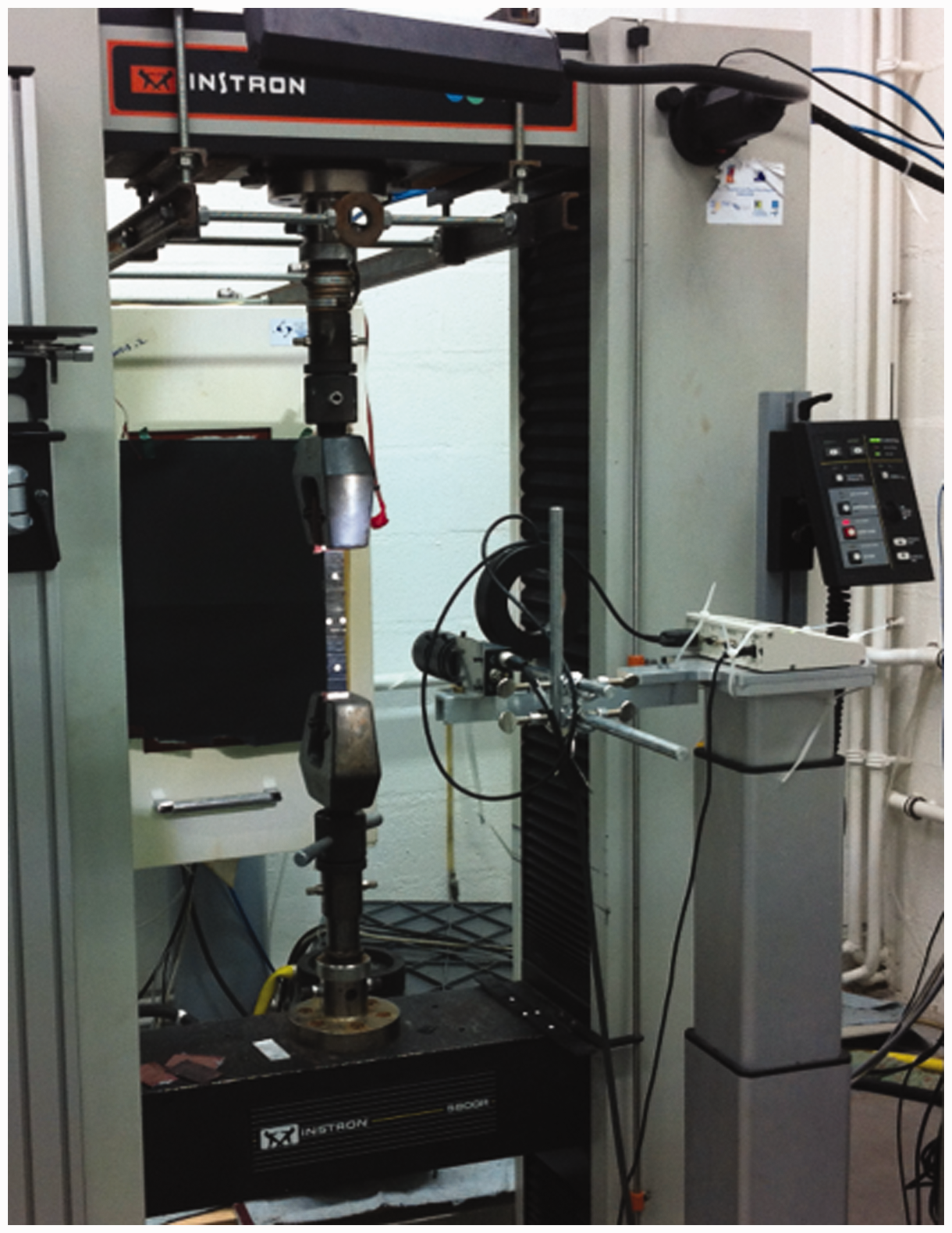
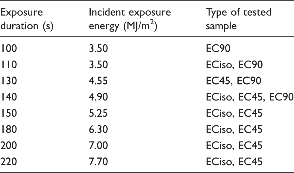
Exposure conditions for each type of sample (the incident heat flux is of 35 kW/m2).
Regarding the mechanical load, a constant displacement is imposed by the actuator to the inner supports of the four-point bending bench (Figure 1(c)). This allows keeping a constant distance between the cone calorimeter and the composite sample and thus a constant value for the incident flux. The compressive side of the sample faces the cone calorimeter. Because of the stiffness drop due to temperature increase, a constant load would lead to an increasing deflection and a reduction of the distance between the cone and the sample. The imposed displacement is a compromise between a value high enough to give rise to a significant stress state in the sample and low enough to avoid the risk of fracture during the thermal aggression. The displacement of the mobile bending supports is thus calculated in the following way:
The ultimate tensile strength has been measured (in Quach et al.
15
) for each type of sample and each condition of fire exposure. The displacement of the mobile supports is calculated so that the maximum stress in the sample under bending is 75% of the ultimate tensile stress.
For the sake of repeatability, three specimens are tested for each condition.
For each test, the temperature is recorded by the thermocouples and the infrared camera and the total mass loss is measured (the samples are weighed before and after the thermomechanical test). After this thermomechanical phase, the samples have been submitted to monotonic tensile load to assess the residual strength.
Temperature evolution recorded by the thermocouples and infrared camera
The first experimental result allowing to assess the effect of the mechanical load on the thermomechanical behavior of the samples is the temperature evolution. Two devices are used to record temperature during the thermomechanical test. First, thermocouples are put on the center of the front and rear faces of the samples. Since these thermocouples provide a local data, the homogeneity of the temperature on the front side has to be checked and the representativeness of the measurement assessed by the means of infrared images of the whole sample surface of the front side. These images are obtained with an ORION SC7000 camera by FLIR.
Figures 3 to 5 display the temperature evolution for each type of sample measured by the thermocouples. “Load” denotes a sample subjected simultaneously to an incident flux of 35 kW/m2 and a constant four-point bending displacement, whereas “no load” means a sample only exposed to the cone calorimeter radiation. The curves have been drawn for the longest exposure durations (220 s for EC45 and ECiso, and 140 s for EC90).
Thermomechanical tests on EC45—evolution of the temperatures recorded by the thermocouples. Thermomechanical tests on ECiso—evolution of the temperatures recorded by the thermocouples. Thermomechanical tests on EC90—evolution of the temperatures recorded by the thermocouples.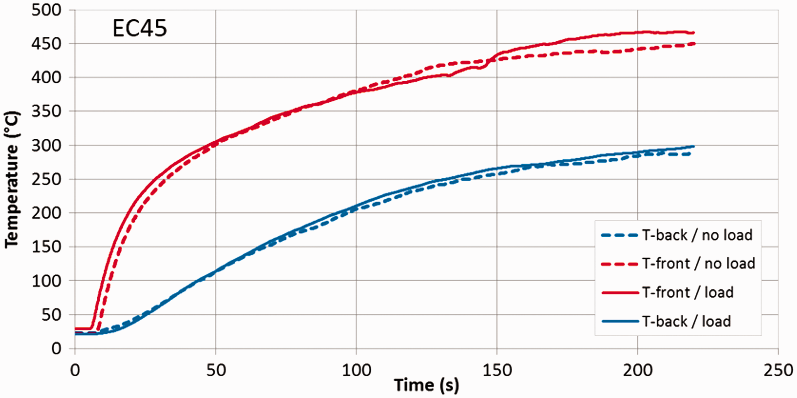
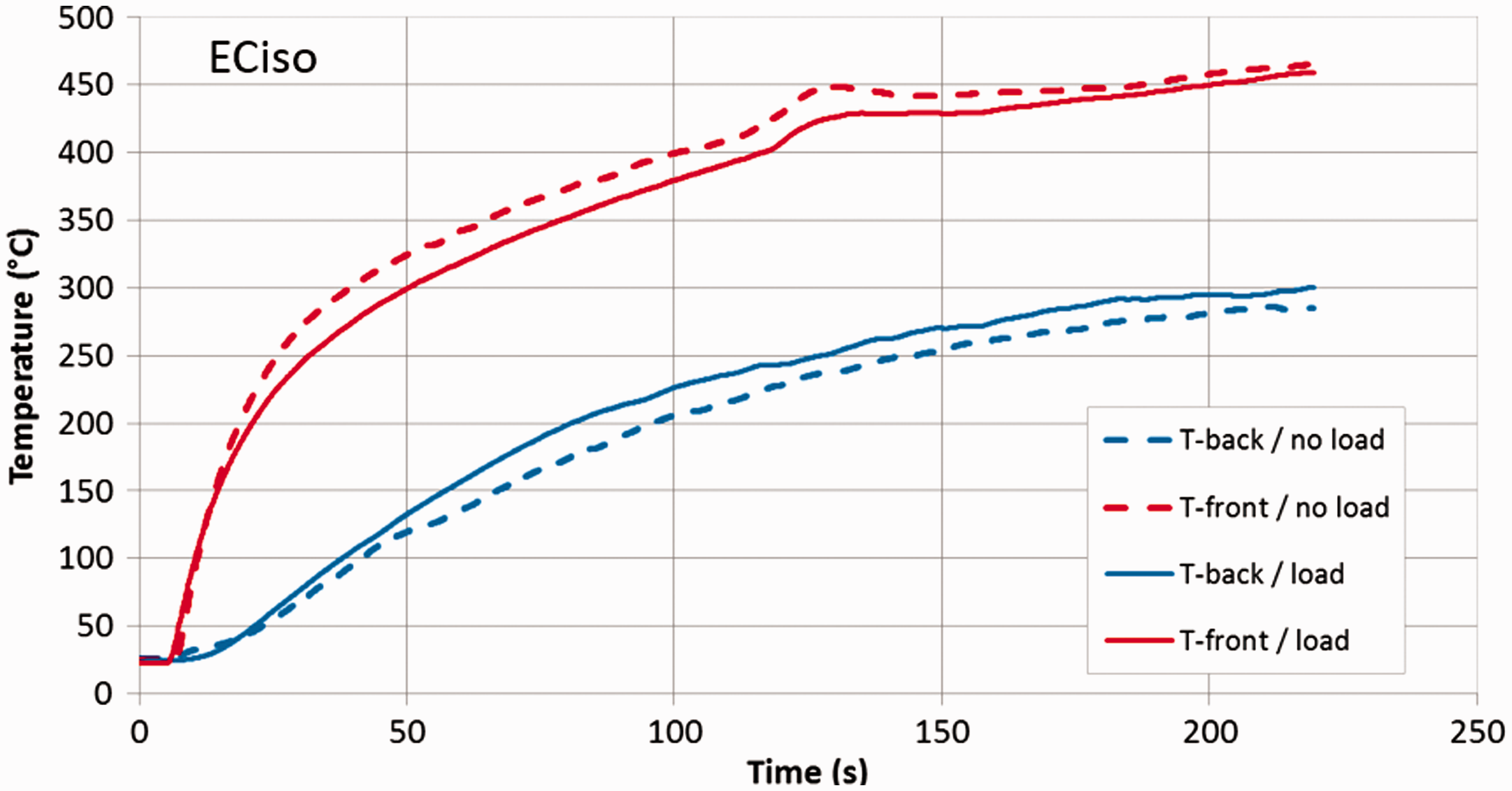
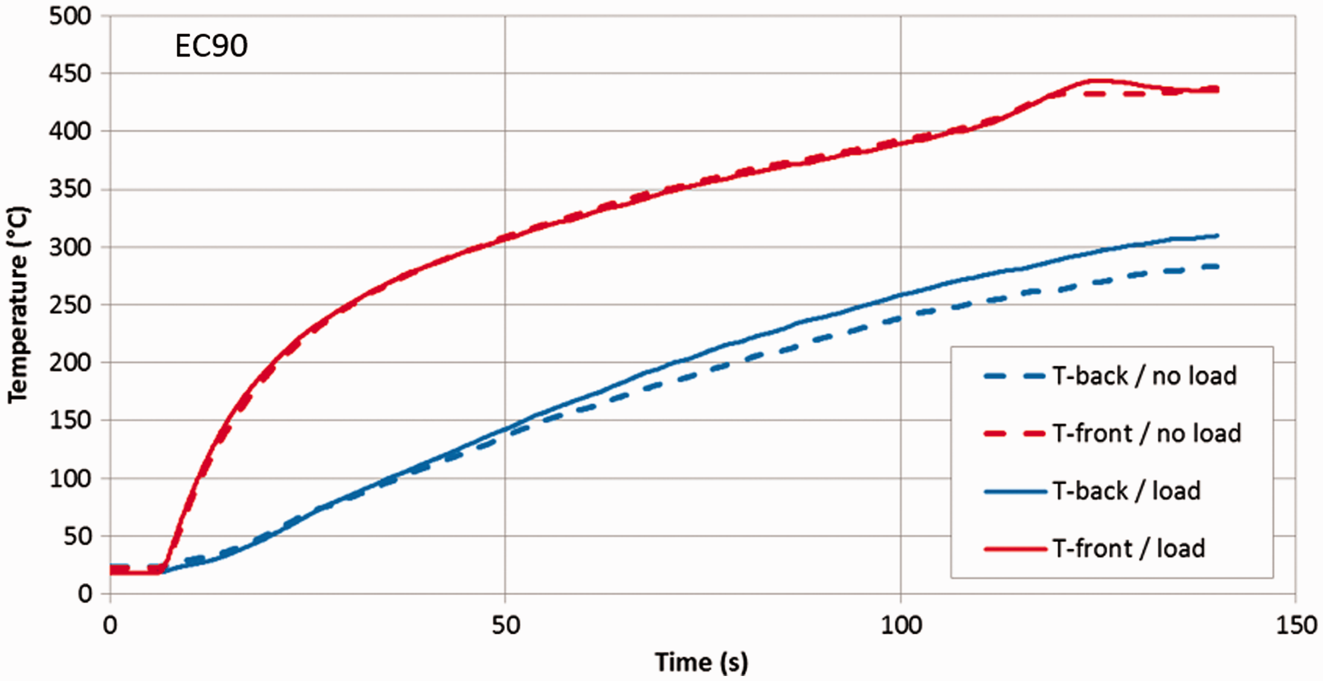
The evolution of the temperature is similar for each type of sample. The plateau in the very first seconds corresponds to the shift of the creep bench in front of the cone calorimeter. The measure recorded by the thermocouple put on the front side of the sample progressively increases in a first stage, whereas this rise is less marked on the rear side, because of the low conductivity of the composite material. At 120–140 s, a slight acceleration can be observed. It corresponds to the ignition process 15 and to the extra thermal flux brought by the flame to the sample. This effect is less marked on the rear face due to the thermal inertia of the composite. No significant differences between the configurations “load” and “no load” can be observed, either for the front side or the rear one. The maximum gap between both curves is about 20℃. No clear trend can be highlighted: according to the test conditions, the temperature “with load” can be slightly below or above the curve “without load.” In conclusion, this first set of results points out that the applied load has very little effect on the thermal properties of the samples.
These observations have been confirmed by infrared camera measurements. The front face that receives the incident flux was observed through the cone calorimeter hole. The measurement range of the camera is between 1.5 and 5.5 µm, but a filter at 3.9 µm was used, as suggested from previous studies by the authors on radiation from flames and irradiated surfaces. This particular wavelength is in a range where standard combustion gases like CO, CO2, and H2O do not contribute to the radiation, thus avoiding the infrared signal to be disturbed by these gases. 22 Moreover, a special care was devoted to the signal processing in order to obtain the temperature distribution in confidence from the infrared flux received from the sample surface. The standard data processing compares the obtained signal with the calibration data usually obtained with a reference source. A high temperature blackbody (M330 by Mikron) was used for this calibration step, with the reference temperature set at 1500℃. Then, the equivalent temperature of the surface can be easily deduced, as the one of the black surface that would emit the same amount of energy than the true surface. However, the true surface is not black. Hence, the difficulty comes from the fact that the signal received by the camera is the sum of the true emission from the surface, plus a nonnegligible part of reflection of the incident flux by the surface.
Therefore, the intensity of the surface can be written as


The reflection term in relation (1) on the right-hand side is even strongly dominant at the beginning of the experiment when the sample is still at low temperature, since the flux from the cone calorimeter is comparable to the one of a blackbody at 992 K.
24
A special postprocessing step was used, involving a signal subtraction to withdraw this reflection. This assumes that the reflection contribution does not change during the whole experiment. Actually, the incidence from the cone can be considered constant as this normalized apparatus is well known for its stable emission. Then, the sample reflectivity must also be constant. This cannot be fully ascertained since radiative properties of surfaces may change with temperature. However, a preliminary characterization was done with a spectrometer, on various samples after different exposition durations (all cooled down before measurement) and no significant variations were observed on the samples. A reflectivity value equal to 0.09 was finally considered as the correct average property at the wavelength of 3.9 µm. The complementary part is the emissivity, equal to 0.91. Knowing these properties, the data processing can be summarized in three steps:
Evaluation of the intensity from the direct signal acquisition thanks to the calibration data obtained with the high temperature blackbody; Calculation of the intensity difference between two successive acquisitions after a Evaluation of the temperature
Initialization was done with 
Examples of images converted in surface temperature are presented in Figure 6, showing the sample as it is seen in the infrared range through the cone aperture. The sample is seen as a rectangle with temperature given in false colors. The case of the ECiso sample submitted to both thermal load and mechanical stress simultaneously is presented at different moments: 10, 80, and 180 s after the beginning of the heating step. As can be seen, the temperature is increasing with time, as expected. There are some few variations on the surface, which rather reveal the surface roughness more than actual temperature variations (the sample shows rough areas because of the winding process and the directional emissivity is affected by the surface orientation). Despite these weak variations, the surface temperature is quite homogeneous. At 180 s, some hot spots are observed, corresponding to the flame which cannot be perfectly deleted by the optical filter and the subtraction processing.
IR images converted in surface temperature (in ℃) for three chosen moments (10, 80, and 180 s). Case of the ECiso samples with mechanical load.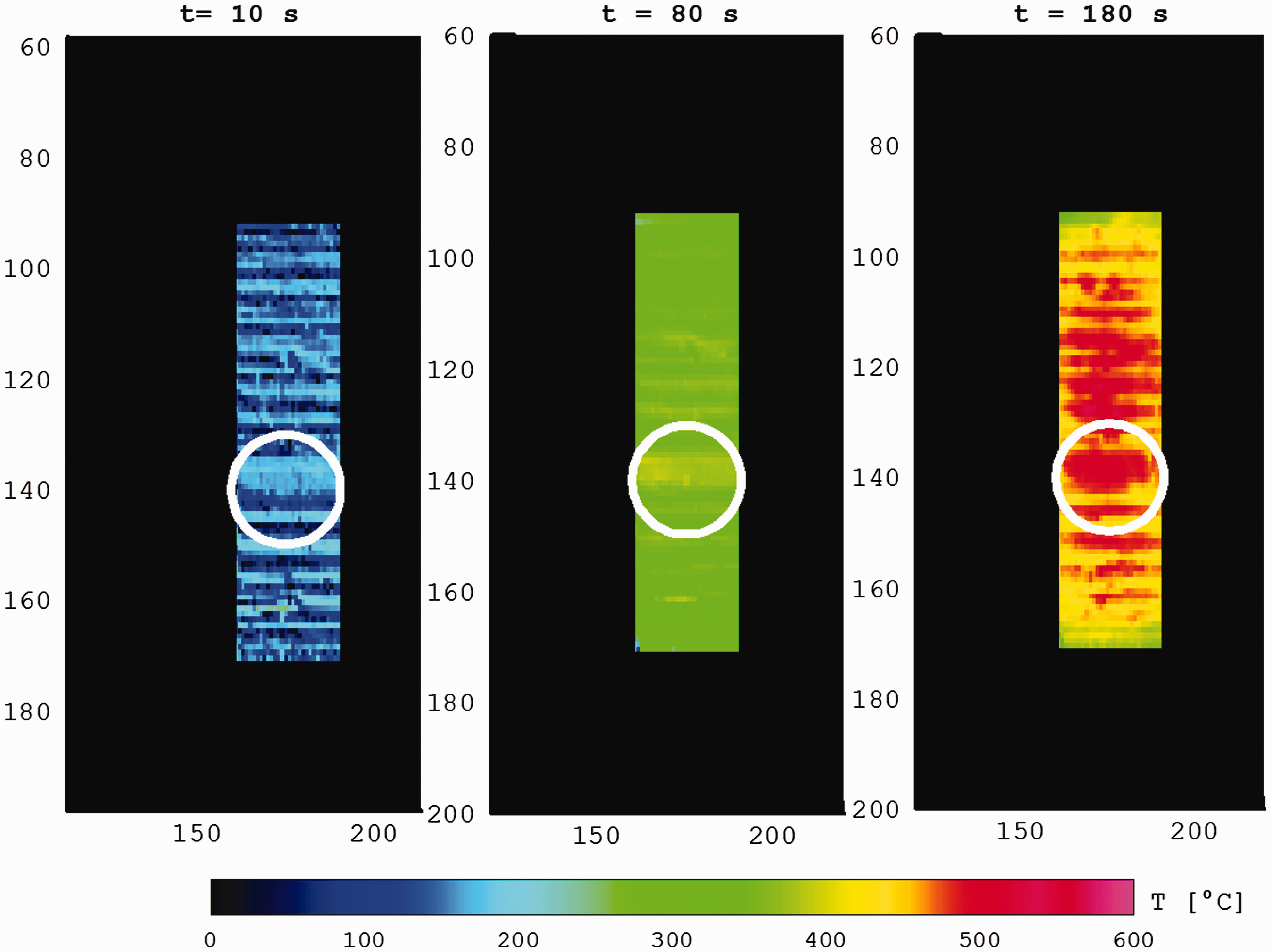
Temperature was averaged on the sample surface, in the area featured by the white circle on the images (which corresponds to a disk with diameter 25 mm approximately) in order to plot the time evolution of the average surface temperature in the next figures.
Figure 7 shows characteristic temperature evolutions as a function of time. The case of the ECiso samples is still presented here, with and without mechanical load, and compared to EC45 and EC90 samples. The increase of the surface temperature with time is in agreement with the experimental data shown in Figures 3 to 5. The values seem to be a little higher than the ones measured with thermocouples, which is not surprising owing to the suspected inertia of the thermocouples and the possible nonperfect contact between the thermocouples and the sample surface. Some measurement biases are also possible with the infrared thermography. The uncertainty in the temperature can be hardly defined with this method, since the errors can come from the infrared measurement itself, the radiative properties, any perturbation of the heat source, in addition to uncertainty in the mechanical load. Despite the use of a dedicated filter at 3.9 µm, there are also some perturbations by soot in the flame when the auto-ignition step is reached (approximately after 100 s according to the curves). The filter avoids any perturbation by the combustion gases but soot emission can still contribute to the measured signal and may produce a slight temperature overestimation. This is another explanation for the slightly higher temperatures reported here as compared to the thermocouple data. Based on a sensitivity analysis and calibration tests, the consecutive measurement uncertainty has been evaluated to 10℃ thanks to a study devoted to this metrological part solely. The agreement is still satisfying between the thermocouples and the IR image processing, however. Regarding the possible effect of coupling between heat transfer and mechanics, no significant variation in the temperature as a function of the load can be obviously deduced from these figures. There are some differences but it can be considered that the observed variations are in the range of the confidence interval of the temperature data. The two dotted lines corresponding to the samples without mechanical load are even in the middle of the curves. Therefore, one can confirm the observation deduced from the thermocouple measurements and conclude that no significant alteration of the temperature surface is observed because of an applied mechanical load. The measurements by infrared camera validate the thermocouple method: although the thermocouple records a local, point-wise temperature, these data are found to be representative of the front side since its temperature is quite homogeneous. This allows considering the temperature recorded by the thermocouple on the rear side with confidence in Figures 3 to 5, which cannot be measured by camera because of the mobile supports.
Temperature evolutions of the front surface for ECiso, EC45, and EC90 samples with and without load.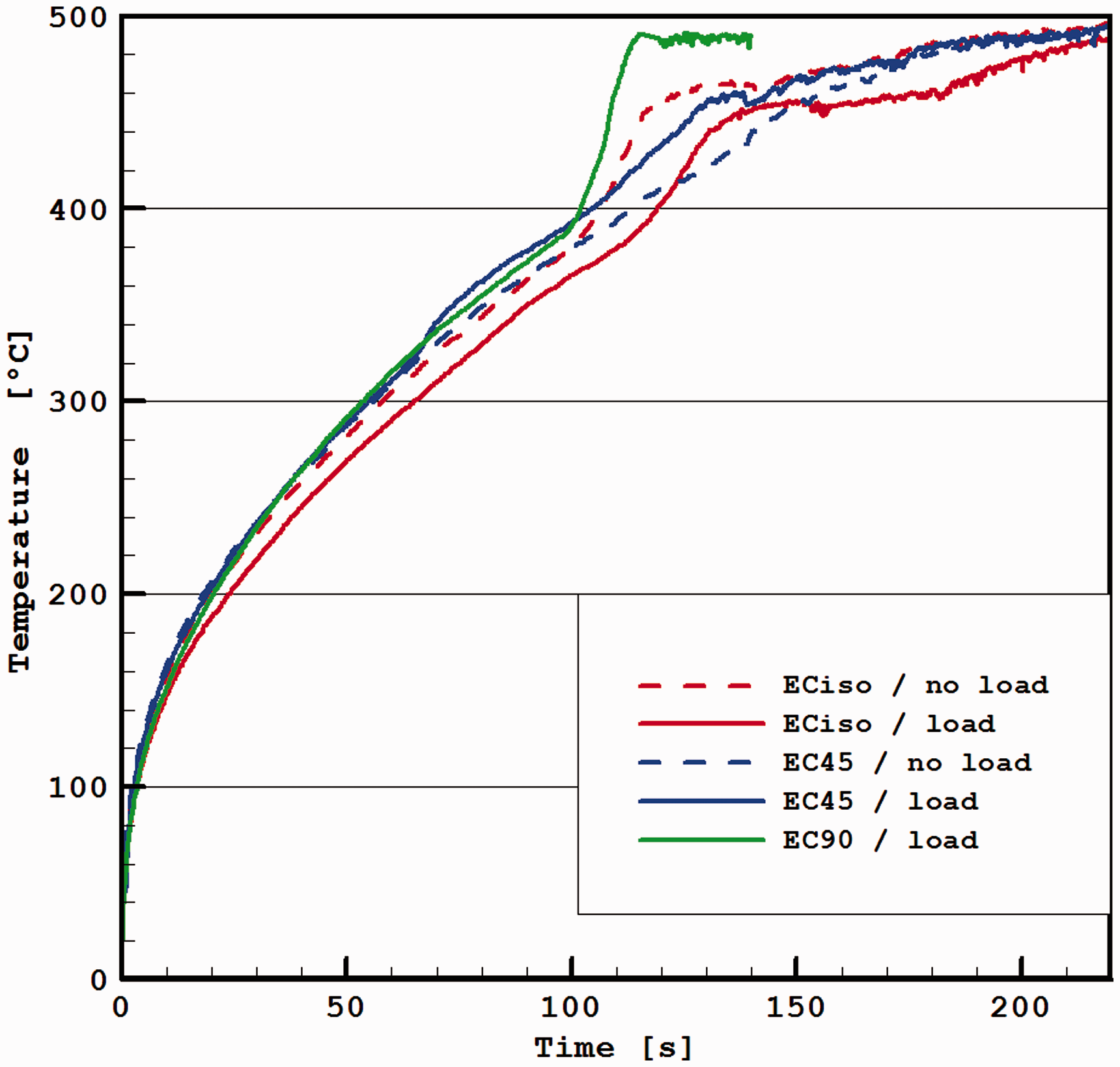
Both temperature measurements evidence that the material thermal properties are not modified by the mechanical stress applied to the sample under heat flux. The coupling between heat transfer and mechanics is consequently one way, in the sense that an incident heat flux may affect the mechanical properties, while the opposite is not seen: a mechanical stress, in the range considered here (a stress level of 75% of the ultimate one, below the damage threshold) does not modify significantly the thermal properties. One can also observe that the curves exhibit a sudden temperature increase after around 100–120 s (a slight shorter time delay as compared to Figures 3 to 5, because time registration exactly starts with the heating step here). As stated in the previous section, this occurs when a spontaneous ignition appears at the sample surface. The flame ignition results in a sudden temperature rise which is a consequence of a change in the incident heat flux because of the contribution of the radiative feedback from the flame. Owing to the sharp increase, one can expect some consequences on the mechanical properties when this occurs.
Regarding the effect of the fiber orientation, no significant evaluation of the effect can be extracted from these data. The EC90 sample exhibits a sharper increase after auto-ignition in Figure 7, but this particular sample was observed to have a significantly higher resin concentration near the surface, which may explain an earlier ignition and a larger temperature jump. This trend is not a consequence of the fiber orientation. The conclusion of a one-way coupling of the heat transfer on the mechanics is confirmed.
Analysis of the mass loss
The possible influence of the temperature fields, studied in “Temperature evolution recorded by the thermocouples and infrared camera” section, on the mechanical properties can be observed through the analysis of the mass loss of the coupons. The mass loss is an evidence of the material degradation, which means a loss of load-bearing capacity and finally a drop of the mechanical strength. Each sample is weighed before and after the coupled thermomechanical loading (cone +bending). The heat energy levels are mentioned in Table 1, for each type of stacking sequence. The mass of the sample decreases when the exposure duration increases. When the sample is subjected to a sufficient energy level, material degradation is observed (the exact degradation kinetics is detailed in the literature15,25). This degradation is evidenced by the change of surface color, the transformation of a part of the composite into gases and char, and the mass loss can be considered as damage leading to mechanical strength decrease.11–13
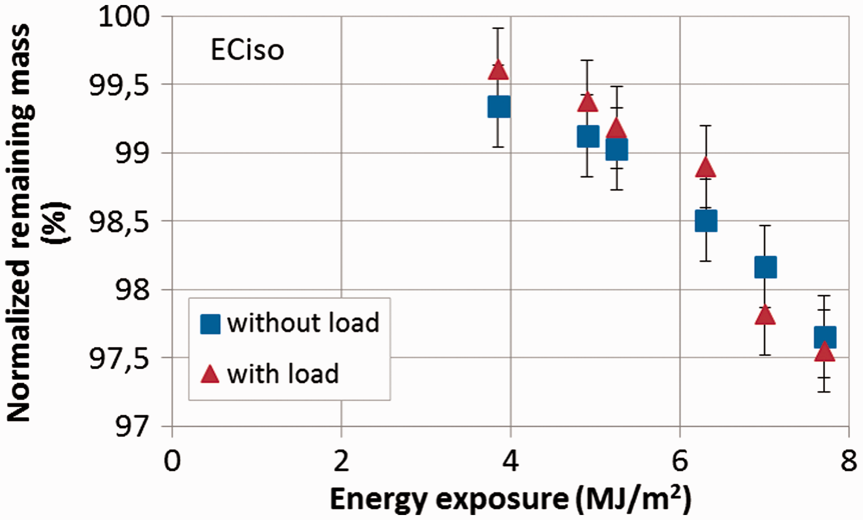
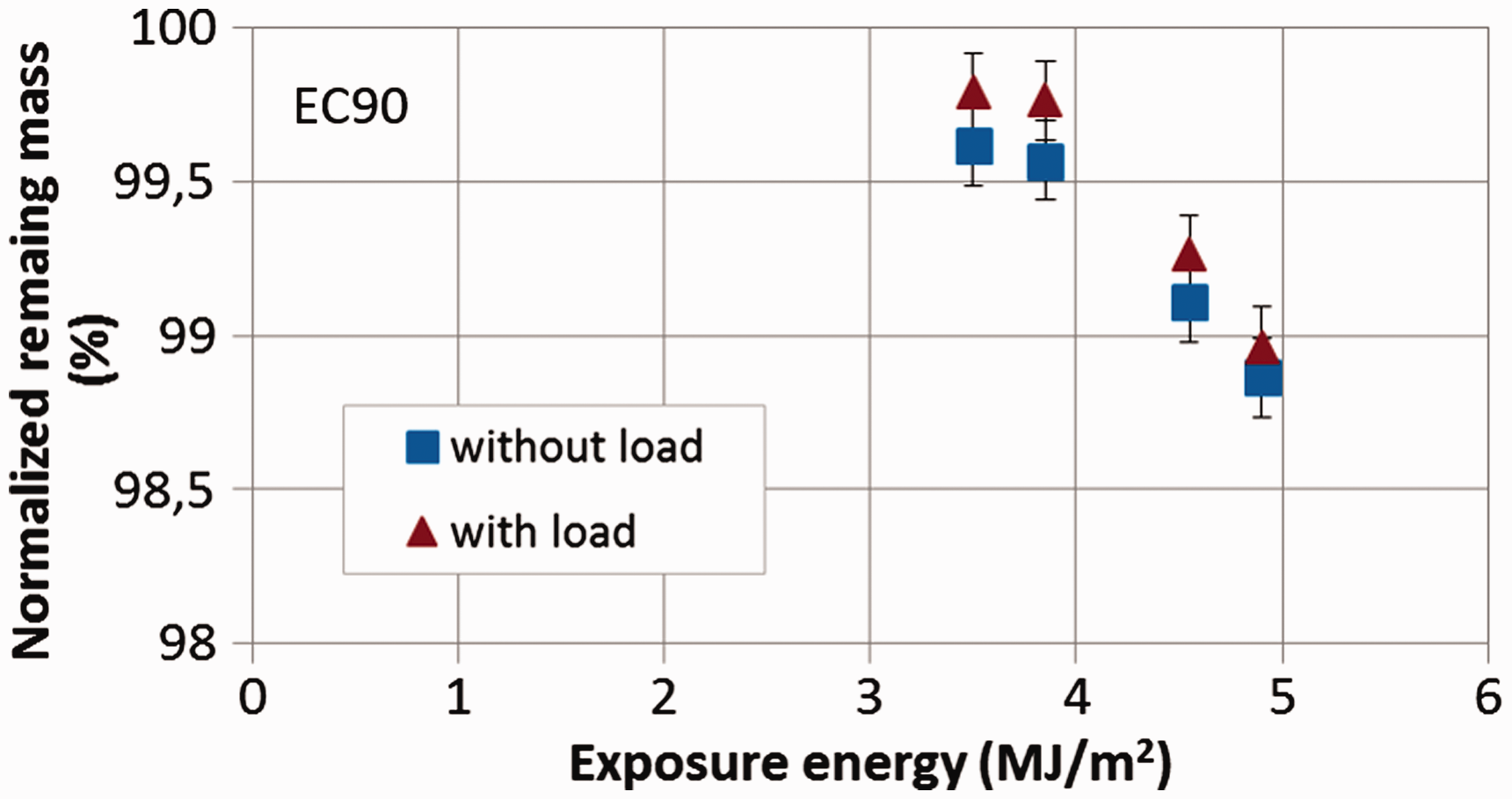
Figures 8 to 10 plot the normalized remaining mass versus the heat energy brought by the cone calorimeter and compare this result in the loaded and nonloaded configurations. The normalized remaining mass is defined as the mass of the sample after heat exposure divided by its initial mass. Each graph clearly shows a mass decrease as soon as the sample ignites. However, this mass loss is independent of the applied load during the “thermomechanical step”: both series of experimental results are very close (within the confidence range) and no clear trend emerges: the mass loss with load is sometimes higher and sometimes lower than the case without load. This conclusion is strongly related to the previous sections: since the material degradation is controlled by the temperature, two similar temperature fields lead to equivalent damage configurations, i.e. mass loss.
Normalized remaining mass of EC45 samples subjected to heat exposure with or without mechanical load. Normalized remaining mass of ECiso samples subjected to heat exposure with or without mechanical load. Normalized remaining mass of EC90 samples subjected to heat exposure with or without mechanical load.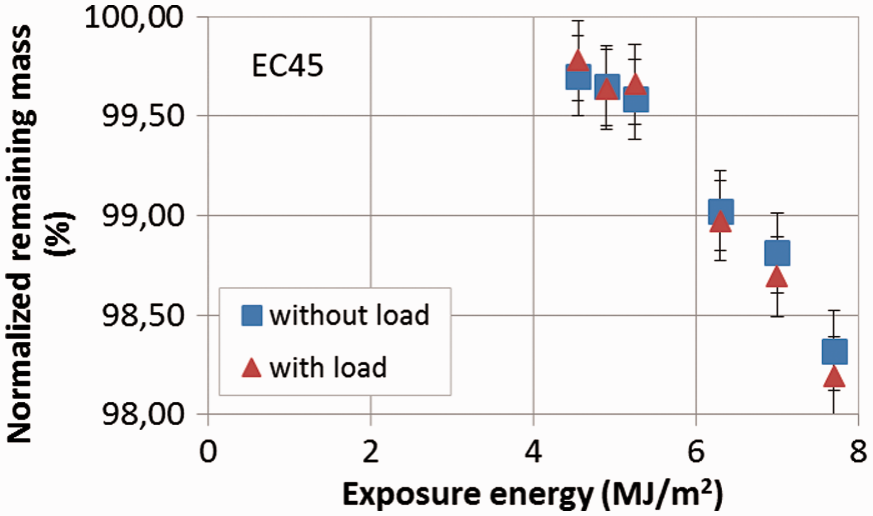
Residual mechanical strength
For the purpose of simulating the time to burst of hydrogen pressure vessels, it is necessary to assess not only the temperature fields but also the residual strength of wound composite materials subjected to a heat flux. “Analysis of the mass loss” section has pointed out the consequence of the cone calorimeter exposure: the volatilization and the charring processes lead to a mass loss of the composite material, which is proportional to the exposure energy. This section addresses the mechanical point of view, by assessing the ultimate tensile strength of the samples which have first undergone a heat flux and a mechanical load (or not). As specified in “Introduction” section, these samples are subjected to a monotonic tension test up to fracture to measure the ultimate tension stress. Figures 11 to 13 plot this strength for each type of sample (loaded or not in the thermomechanical aggression phase) and each incident heat flux specified in Table 1. The “normalized tensile strength” denotes the tensile strength measured for a given heat exposure condition divided by the tensile strength of a sample which has not been exposed to fire. The error bars take into account the experimental dispersion observed in each batch of samples tested in the same conditions.
Normalized tensile strength of EC45 samples subjected to heat exposure with or without mechanical load. Normalized tensile strength of ECiso samples subjected to heat exposure with or without mechanical load. Normalized tensile strength of EC90 samples subjected to heat exposure with or without mechanical load.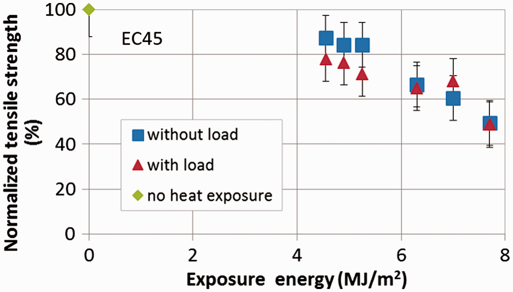
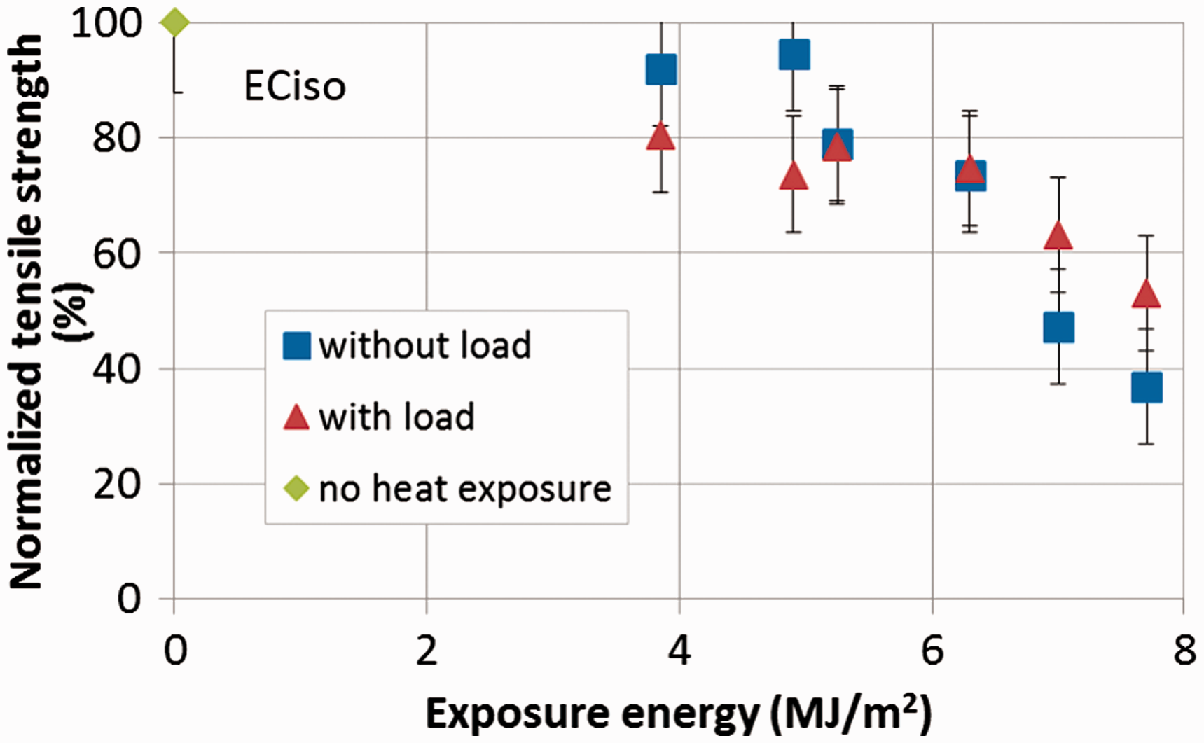
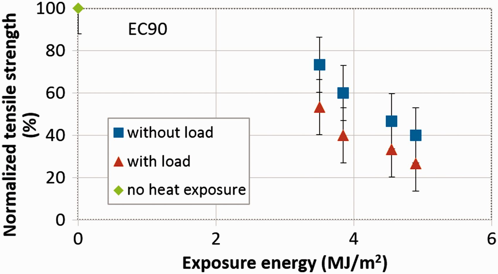
For all exposed samples, the energy input clearly affects the tensile strength: the longer the exposure duration, the lower the strength. For each type of stacking sequence, the failure mode (see Quach et al. 15 ) is independent of the mechanical stress applied (or not) during the thermomechanical step of the test: the fracture mode of EC90 is a brittle fiber/matrix debonding, EC45 undergoes more progressive damage until failure by delamination, and ECiso behavior is characterized by a slight microcracking before final delamination.
The experimental results obtained for EC45 and ECiso samples are very similar. The heat exposure leads to a progressive decrease of the mechanical properties. The application of a bending moment does not seem to affect the strength: no clear trend can be identified. The values of the normalized strength with load are alternately higher or lower than those obtained without load. Furthermore, the difference between the two sets of values falls in the uncertainty range. The results for EC90 are slightly different: the normalized strength with load is systematically lower than the value without load. However, it is important to keep in mind that the uncertainty range for this type of sample is quite large: the brittle failure mode is very sensitive to defects at the interface fiber/matrix and consequently the dispersion of the measured tensile strength is very important, all the more since only four exposure levels have been investigated.
Conclusion
The thermomechanical consequences of a mechanical load during a heat exposure have been investigated thanks to the development of a specific experimental setup associating a cone calorimeter and a four-point bending bench. By comparing the temperature, the mass loss, and the tensile strength of samples subjected to a coupled thermomechanical load or only a heat flux, it can be concluded that:
The bending mechanical load does not affect substantially the temperature measured on the front side by thermocouples or an infrared camera during the thermomechanical loading. The temperature on the rear side is also insensitive to the bending load. Thus, it can be inferred that the thermal properties are not significantly modified by the bending load. As a consequence, since the charring kinetics is controlled by the temperature, the mass loss (due to the transformation of the composite into char) is similar when the coupons are loaded or not. Once cooled down, the samples are subjected to tension in order to measure the influence of the load on the strength. The difference between both configurations (loaded or not) falls within the uncertainty range, so that no effect of the load can be unequivocally exhibited.
The weak influence of the load during the thermomechanical step can be explained by the rapid relaxation of the stress in the sample, as it can be observed in Figure 14. Note that the mechanical stress is due to a constant bending displacement applied to the mobile supports of the four-point bending setup (Figure 1). The corresponding load is measured by a cell. The evolution of this load (divided by the value at the beginning of the test) is presented in Figure 14. The small increase at the very beginning is due to the expansion of the layers facing the cone. This hump shape is rapidly followed by a decrease of the load caused by the stiffness drop when the temperature increases through the sample thickness. The force reaches almost zero at about 50 s. From this moment, the sample no longer undergoes mechanical stress and then no difference between the loaded and nonloaded sample is observed. In conclusion, for the further simulation of structures subjected to mechanical load and a heat exposure, it is pivotal to accurately model the effect of charring on the mechanical properties, but conversely, the influence of the bending mechanical stress on the thermal properties does not seem to be of major importance.
Evolution of the normalized bending force during the thermomechanical step (EC45 sample).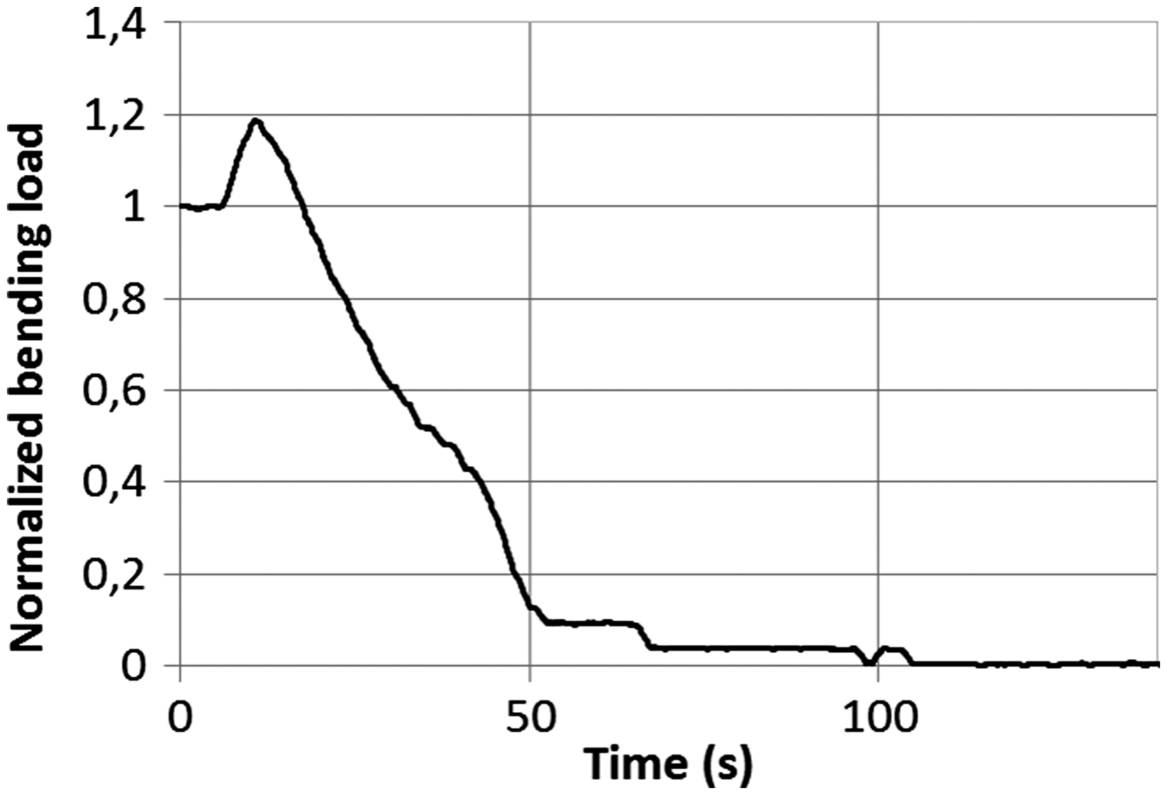
Footnotes
Acknowledgements
This work pertains to the French Government program “Investissements d’Avenir” (LABEX INTERACTIFS, reference ANR-11-LABX-0017-01).
Declaration of Conflicting Interests
The author(s) declared no potential conflicts of interest with respect to the research, authorship, and/or publication of this article.
Funding
The author(s) disclosed receipt of the following financial support for the research, authorship, and/or publication of this article: The research leading to these results has received funding from the European Union’s Seventh Framework Program (FP7/2007-2013) for the Fuel Cells and Hydrogen Joint Technology Initiative under grant agreement no. 325329.