






Abstract
Natural fiber-reinforced composites are increasingly being used in the industry. The fiber–matrix interfacial properties of the composites are influenced by many factors, including chemical treatment of the natural fiber, type of polymer matrix, composites fabrication method, and process and the service environment of the composites. In this paper, a modified shear-lag model based on a cohesive fiber/matrix interface is proposed and applied to the analysis of the stress–transfer characteristics and the tensile properties of unidirectional short flax fiber-reinforced composites. The model takes into account of the interfacial shear stiffness, bonding strength between fiber end face and matrix, fiber aspect ratio and fiber volume fraction. 3D finite element models of the composites using a cohesive zone method are used to verify the accuracy of the modified shear-lag model. The fiber tensile strength and the composite tensile elastic modulus are significantly influenced by the interfacial shear stiffness, fiber aspect ratio, and fiber volume fraction. The bonding strength between the fiber end face and the matrix only has an effect when the interfacial shear stiffness is low. The predicted results from the modified shear-lag model show good agreement with the finite element analysis and experimental results in the literature. The modified cohesive shear-lag model provides a simple and effective method for analyzing fiber axial stress, shear stress in the fiber/matrix interface, and tensile elastic modulus of the final composite.
Keywords
Introduction
Natural fibers, such as flax, hemp, kenaf, and bamboo are being widely used as reinforcements for composite materials. Compared with traditional synthetic fibers, such as carbon and glass fibers, natural fibers are abundant, lightweight, biodegradable, recyclable, and available at a low price. In addition, the specific mechanical properties of natural fibers are comparable to those of glass fibers used as reinforcement materials.1–3 This has led to increasing industrial application of natural fiber composites.4–6 Short natural fiber-reinforced composites (SNFRCs) have been used in nonstructural parts in the automobile industry primarily because they can be easily fabricated by the rapid, low-cost injection-molding process.7,8
There are a number of factors influencing the mechanical properties of SNFRCs, including the distributions of fiber length and orientation in the final composites, the intrinsic mechanical properties of the fiber and the matrix, and the fiber/matrix interfacial properties. The fiber/matrix interface plays an important role in the load transfer between the fiber and the matrix, which in turn determines the mechanical properties of fiber-reinforced composites, such as elastic modulus, tensile strength, and fracture toughness.9–11 In comparison to glass fiber and carbon fiber composites, the interfacial shear properties between the natural fiber and matrix are generally poor and can easily deteriorate in humid environment. 12 Efficient and accurate models that predict the effect of fiber/matrix interface properties on the mechanical behavior of SNFRCs are useful to guide research aimed for improvement of natural fiber/matrix interface.
The classical shear-lag model (SLM) developed by Cox was the first micromechanics model for predicting the elastic properties of short-fiber composites based on computation of the stress distribution in the fiber, matrix, and fiber/matrix interface. 13 Since then, modifications to the classical SLM have been made to improve prediction results for specific uses.14–21 Nardone and Prewo 19 took into account the load transferred from the matrix to the end faces of the fiber that had been ignored in Cox’s original SLM, 13 in which fiber was considered to be either continuous or very long relative to diameter. A modified SLM developed by Ji and Zhao 18 incorporated the influences of fiber shape on the tensile stress distribution in the fiber. Zhang and Qiu 21 developed a modified SLM for fibers with irregular cross-sectional shapes to provide accurate calculations for interfacial shear stress through introducing an equivalent diameter of fiber and a dimensionless shear-lag constant in the classical SLM. Virk et al. 22 introduced a fiber area correction factor (FACF) to transfer fiber properties from values based on apparent cross-sectional area (CSA) to values based on the statistically corrected true CSA for the fiber batch in the generalized rule of mixtures equation. They achieved accurate prediction of the modulus and strength of SNFRCs. McCartney 16 introduced interfacial friction in SLM in the analysis of interfacial debonding during fiber pullout or pushout.
Finite element (FE) modeling is now widely used in the simulation of fiber-reinforced composites thanks to recent advancement in numerical simulation and computer software. A number of research groups have proposed a number of methods to characterize the fiber/matrix interface for use in FE modeling of fiber-reinforced composites, including the cohesive zone method (CZM),23–25 the perfect bonding method,26,27 and the frictional contact method. 9 The FE models developed by Modniks and Andersons 26 and Modniks et al. 27 to investigate the influence of fiber volume fraction on the mechanical properties of flax fiber-reinforced polymer matrix composites assumed a perfect fiber/matrix adhesion, i.e., the interface will never fail when the composite is subjected to external loading. Guillebaud-Bonnafous et al. 9 developed a 2D FE model of fragmentation test based on two different contact interactions in the interface, a perfect bonding and a frictional contact, and used the model to investigate the adhesion properties in hemp yarn–matrix composites. Modniks and Andersons 23 simulated the nonlinear deformation of a short flax fiber-reinforced composite accounting for the effect of the interfacial shear strength using the CZM. Shokrian et al. 25 established 3D FE models of a short glass fiber-reinforced composite using CZM to study the longitudinal and transverse tensile behavior of the composite material with different interfacial shear strength. Chen and Yan 24 introduced cohesive fiber/matrix interface into the classical SLM to analyze the stress distribution of fiber pullout and developed FE models based on CZM to simulate fiber pullout and to verify the accuracy of the refined SLM. Insofar, CZM-based FE modeling is the most effective and convenient approach to numerical simulation of the cohesive behavior of fiber/matrix interface.
As discussed above, most investigations on the micromechanical properties of short fiber–reinforced composites (SFRCs) using the SLM are based on the perfect bonding between the fiber and matrix.14–21 However, the tensile modulus of the SNFRCs can be overestimated using SLM based on the assumption of perfect bonding for the poor adhesion between hydrophilic natural fibers and hydrophobic polymer matrix. 28 No study of the stress distribution of short fiber–reinforced composite systems using SLM with consideration of the cohesive behaviors of fiber/matrix interface has been identified, except for the work on fiber pullout from single fiber composites by Chen and Yan. 24 In this work, we used the experimental load–displacement curves microdroplet tests12,29 to construct cohesion behaviors of the natural fiber/matrix interface and establish a modified SLM to analyze the elastic properties of the SNFRCs. Using this modified SLM, we investigated the effects of cohesive interfacial shear stiffness, elastic properties of the fiber and the matrix, fiber aspect ratio, and average fiber axial stress at the embedded end face of fiber on the stress–transfer characteristics and axial tensile properties of the composite. The axial stress in the fiber and the tensile elastic modulus of the composite are compared to published experimental data.
A modified SLM with a cohesive fiber/matrix interface
A cylindrical fiber was always adopted in the modeling of flax fiber–reinforced composites to simplify the analysis of stress transferring at the fiber–matirx interface and achieved remarkably accurate predictions of experimental data.23,26,27 Figure 1 shows a general unit cell consisting of a cylindrical discontinuous fiber of length Schematic diagram of a unit cell with a cohesive fiber/matrix interface.
Experimental pullout curves12,29 can be used as basis to construct a cohesive traction–separation function that describes the shear behavior of the cohesive interface, as shown in Figure 2. The cohesive traction–separation constitutive relation is expressed in equation (1).


As the modified SLM with a cohesive fibre/matrix interface in this study is based on the classical SLM 13 and the modified SLM,14–17,24 the basic hypotheses inherent in a shear-lag analysis can also be invoked, except for the discontinuous displacement between the fiber and the matrix at the cohesive interface.
In our modified SLM, the material properties of the fiber and the matrix are assumed to be isotropic elastic and are described by Hooke’s laws:
17

The shear stress distribution in the fiber and matrix are assumed to be of the form:
16

According to the basic assumption of the SLM,19,31 the axial tensile and shear strains of the fiber or the matrix can be given in terms of the axial displacement

The displacement crossing the interface (

Combining equations (2) to (5), the relation among the average axial displacements of the fiber (


Considering the load equilibrium of an infinitesimal element of the fiber and the matrix at a distance of z,
31
the average axial stress of the fiber (


Differentiate equation (6) with respect to z yields

Averaging equation (2) over the fiber cross section and the matrix cross section, respectively, we obtain the average axial strain of the fiber (

By adopting equation (12) proposed in Nairn,
17
equation (11) can be simplified to equation (13).


As the total force on any cross section of the unit cell in the z-direction should be equal to the force acted on its end (Figure 1), we have

Differentiating equation (8) and substituting it together with equations (13) and (14) into equation (10) yield
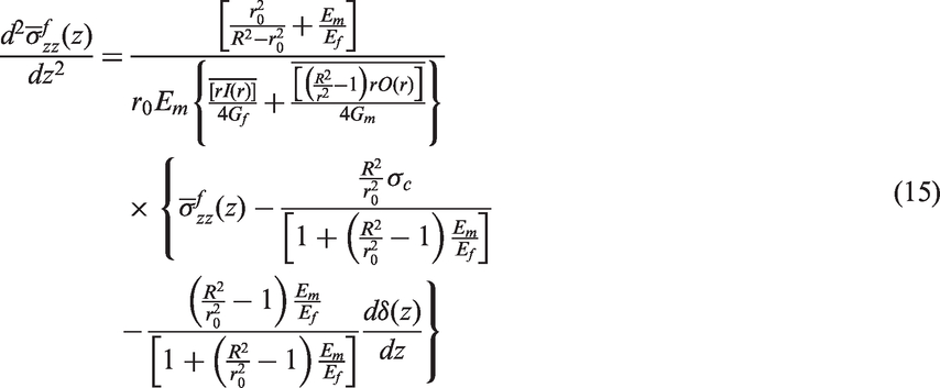
In conclusion, the governing equations for the SLM with a cohesive fiber/matrix interface are made up of equations (15), (8) and (1). The stress distribution in the fiber and matrix, and the axial tensile modulus of the composite can be computed from the above governing equations subjecting to appropriate boundary conditions. For clarity, the average of the axial tensile stress in the fiber (
Analysis of the tensile modulus and stress of the composites
In this part, the modified SLM is applied to the analysis of the axial tensile properties of the natural fiber composites in the initial linear elastic stage. At this stage, the damage of the cohesive fiber/matrix interface does not appear and the shear stiffness of the cohesive interface is equal to K0. By differentiating equation (1) and combining with equation (8), we find
24

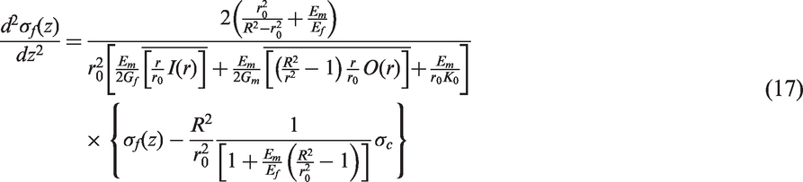
Substituting equation (16) into equation (15), it can be obtained that:
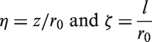
We also introduce the following scaling parameters:
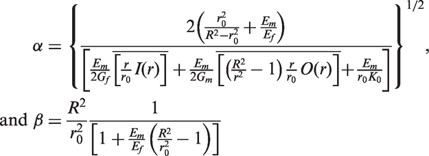
Assuming
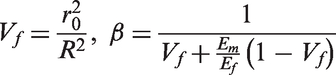
Then, equation (17) can be expressed as:


Note that the unit cell in this paper is different from that by Chen and Yan,
24
which leads to a different load equilibrium condition in equation (14) and a different β value. On the other hand, the shear-lag parameter α is the same as that obtained by Chen. When the initial interfacial shear stiffness K0 is significantly greater than
The unit cell in Figure 1 is symmetrical about the middle point

Solving the second-order differential equation (18) subjecting to the boundary conditions in equation (20) yields



When the fiber volume fraction is very small (
The average axial strain of the matrix

In order to predict the axial tensile Young’s modulus of the composite, it can be assumed that the average strains in the matrix and the composite are equal.
33

The axial Young’s modulus of the composite Ec can thus be obtained:

Equation (26) describes the relationship between the axial Young’s modulus of the composite Ec and the Young’s modulus of matrix Em. Equation (26) tells us that Em, Ef, ϕ, K0, and ζ can influence the axial tensile Young’s modulus of the composite.
FE model of the unit cell
A meshed 3D FE model of the unit cell containing a flax fiber embedded in the matrix and a thin interface layer of cohesive elements is presented in Figure 3. The two end faces of the fiber are free from the matrix. The axial displacement at the left end face of the matrix is constrained and a uniform displacement load is applied to the right end face of the matrix. The matrix and the fiber are meshed with linear hexahedral elements (C3D8R), as well as the interface layer meshed with cohesive elements (COH3D8).
FE model of the unit cell.
The properties of the fiber and matrix. 23

To investigate the effect of fiber volume fraction (Vf) on the tensile properties of the composite, the geometric model of the unit cell needs to be adjusted according to the Vf. As the radius of the flax fiber is constant, the length of the fiber can be calculated from equation (27). According to the assumption in Analysis of the tensile modulus and stress of the composites section, in the FE model of the unit cell, the length of the matrix is set to be slightly larger than the length of the fiber. Therefore, the radius of the unit cell (R) can be obtained from equation (28). In the FE models of the unit cell, the values of the Vf are assumed to be 0.1, 0.2, and 0.3.


Results and discussion
Axial tensile stress in the fiber
Different assumptions on the radial dependence of the shear stress in the fiber and matrix have been developed in SLMs.13,14,16,17 In this paper, we adopt the assumption The shear-lag parameter as a function of 
The longitudinal tensile stress in the flax fiber surrounded by the polypropylene (PP) matrix as functions of the fiber aspect ratio (ζ), fiber volume fraction (Vf), and the ratio Longitudinal distribution of relative tensile stress in the fiber as a function of (a)ζ, (b)Vf, and (c) 
Figure 6 compares the longitudinal distribution of relative tensile stress in the fiber calculated from equation (21) with finite element analysis (FEA) results. There is a strong agreement between the FEA results and our results based on the modified SLM with a cohesive fiber/matrix interface. The main difference is that the longitudinal tensile stress in the two ends of the fiber from FEA is higher than that from the modified SLM. This is caused by stress concentration, which has not been taken into account in equation (21). This supports the proposed modified SLM for the analysis of the fiber tensile stress.
Comparison of the relative tensile stress predicted by the modified SLM with the FEA results.
According to the above discussion, it can be concluded that fiber aspect ratio ζ, fibre volume fraction Vf, and the
Elastic modulus of composites
The longitudinal elastic modulus of unidirectional short flax fibre–reinforced PP matrix composite as functions of fiber aspect ratio (ζ), fiber volume fraction (Vf), and ratio Longitudinal tensile modulus of the composite as functions of (a) the fiber aspect ratio (ζ), (b) the fiber volume fraction (Vf), and (c) the ratio 
Figure 8 shows the influence of the bonding strength between the fiber end face and the matrix on the longitudinal tensile modulus of the composite. The top of the error bar represents the value of Ec at Influence of the bonding strength between the fiber end face and the matrix on the longitudinal tensile modulus of the composite.
Figure 9 presents the longitudinal tensile modulus of the composite as a function of the ratio Comparison of the longitudinal tensile modulus of the composite predicted by the modified SLM with FEA results as a function of the ratio 
The longitudinal tensile modulus of the composite with a high interfacial shear stiffness calculated from equation (26) is compared with that calculated from the Halpin–Tsai model,
36
which was used to predict the elastic modulus of natural fiber–reinforced thermoplastics in Facca et al.
28
As shown in Figure 10, the results from the modified SLM and Halpin–Tsai model match each other very well, indicating that the modified SLM has the same accuracy in predicting the tensile modulus of a composite with a perfectly bonded interface by assuming a large interfacial shear stiffness. The advantage of the proposed modified SLM is that it is also capable of predicting the elastic modulus of composites with any initial interfacial shear stiffness.
Comparison of the longitudinal tensile modulus of the composite with a high interfacial shear stiffness predicted by the modified SLM and that by the Halpin–Tsai model.
Comparison to experiment results
Tensile stress and strain in fiber
A great deal of results have been published on the stress–transfer characteristics of the single fiber–reinforced polymeric composite in fragmentation experiments using Laser Raman spectroscopy.35,37,38 Different volume fractions of short fiber in epoxy composites were loaded up to the levels of stress sufficient to cause interfacial failure and the fiber strain profiles in the fragmentation processes were determined at each level of applied stress. 35
Figure 11 compares the experimentally determined fiber tensile strain along the length of the fiber in different carbon fibre–reinforced epoxy composites at an applied strain of 1%
35
to the predicted strain using the modified SLM. In the fragmentation test, the applied strain was transferred to the fiber from the matrix through the fiber/matrix interface and both end faces of the fiber were free from any constraint by the matrix. Therefore, value of ϕ should be zero value in the calculation of the fiber tensile stress by the modified SLM for the fragmentation test. The fiber tensile strain Comparison between analytical predictions and experimental results of fiber strain distribution in fragmentation test of single fiber composites.

Figure 11 shows a good agreement between the experiment data and the results obtained from the modified SLM using appropriate shear stiffness of the cohesive interface. Combining the experiment data with the prediction results, we can find that the interfacial shear stiffness between the carbon fiber without electrolytic surface oxidative treatment and epoxy is much less than that of the carbon fiber with electrolytic surface oxidative treatment and epoxy. The low interfacial shear stiffness between the untreated carbon fiber and the matrix leads to the decrease of maximum strain in the fiber, as shown in Figure 11. Therefore, the modified SLM with a cohesive fiber/matrix interface can be used to analyze the stress–transfer characteristics of fiber-reinforced composite with different interfacial properties.
Elastic modulus of composite
The mechanical properties of short flax fiber–reinforced polymeric composites have been widely studied using FE model of a unit cell made of a single fiber embedded in matrix and equating the fiber volume fraction to that of the actual composites.23,26 The tensile elastic modulus of the composites with different flax fiber volume fractions had been obtained from the FE models by Modniks and Andersons. 26 The Young’s modulus of the flax fiber and matrix used in their FE models were 69 GPa and 1.6 GPa, respectively. The length and the diameter of the flax fiber were 1.21 mm and 16 µm, respectively.
Comparison of the tensile elastic modulus of a short flax fiber-reinforced polymeric composite.

SLA: shear-lag model.
Conclusions
In this paper, a modified SLM with a cohesive fiber/matrix interface is developed and applied to the analysis of the effect of interfacial properties on the elastic properties of unidirectional short flax fiber-reinforced polymeric composites. 3D FE models of the composite material accounting for the fiber/matrix interfacial properties are built using CZM to simulate the tensile properties of the composite. The tensile stress in the fiber and the tensile elastic modulus of the composite with different interfacial properties, fiber aspect ratios, and fiber volume fractions are computed using both the modified SLM and the FE models.
The analytical solutions show that the interfacial shear stiffness, fiber aspect ratio, and fiber volume fraction all have significant effects on the tensile stress of the fiber and the tensile elastic modulus of the composite. The maxima of the fiber relative tensile stress and the composite tensile elastic modulus increase with the increase of the interfacial shear stiffness and the fiber aspect ratio and then plateau after a critical interfacial shear stiffness and a critical fiber aspect ratio have been reached. The maximum of the fiber relative tensile stress decreases with the increase of the fiber volume fraction, while the tensile elastic modulus of the composite increases with the increase of the fiber volume fraction. The bonding strength between the fiber end face and the matrix has a great influence on the tensile elastic modulus of the composite at low fiber aspect ratio and low interfacial shear stiffness. At high fiber aspect ratio and high interfacial shear stiffness, this influence becomes quite small. The prediction of composite tensile elastic modulus using the modified SLM agrees well with that calculated from the Halpin–Tsai model when the product of the interfacial shear stiffness and the fiber radius (
There is a strong agreement between the predicted results using the modified SLM and the simulation results obtained from the FE models using CZM. The predicted fiber tensile stresses using the appropriate interfacial cohesive properties fitted published experimental results using Laser Raman Spectroscopy technique very well. The predicted tensile modulus of the composite using appropriate interfacial cohesive stiffness and fiber end face coefficient showed a good agreement with the simulation results using the FE models by assuming both the two fiber end faces are perfectly bonded with the matrix. The modified SLM provides a simple and effective method for the analysis of the stress–transfer characteristics and axial tensile properties of short fibre–reinforced composites accounting for the interfacial shear stiffness, fiber aspect ratio, fiber volume fraction and bonding strength between the fiber end face and the matrix.
Footnotes
Declaration of Conflicting Interests
The author(s) declared no potential conflicts of interest with respect to the research, authorship, and/or publication of this article.
Funding
The author(s) disclosed receipt of the following financial support for the research, authorship, and/or publication of this article: The authors acknowledge the financial support from CSIRO Manufacturing, National Natural Science Foundation of China (No.51575417), Innovative Research Team Development Program of Ministry of Education of China (No. IRT_17R83), and 111 Project (No. B17034). Xiaoshuang Xiong also gratefully acknowledges the scholarship from China Scholarship Council (201606950038) which enabled the work at CSIRO in Australia.