
Abstract
In this study, multi-layered composite overwrapped pressure vessels for high-pressure gaseous storage were designed, modeled by finite element method and manufactured by filament winding technique. 34CrMo4 steel was selected as a load-sharing metallic liner. Glass and carbon filaments were overwrapped on the liner with a winding angle of [±11°/90°2]3 to obtain fully overwrapped composite reinforced vessel with non-identical front and back dome endings. The vessels were loaded with increasing internal pressure up to the burst pressure level. The mechanical performances of pressure vessels, (i) fully overwrapped with glass fibers and (ii) with additional two carbon hoop layers on the cylindrical section, were investigated by both experimental and numerical approaches. In numerical approaches, finite element analysis was performed featuring a simple progressive damage model available in ANSYS software package for the composite section. The metal liner was modeled as elastic–plastic material. The results reveal that the finite element model provides a good correlation between experimental and numerical strain results for the vessels, together with the indication of the positive effect on radial deformation of the COPVs due to the composite interlayer hybridization. The constructed model was also able to predict experimental burst pressures within a range of 8%. However, the experimental and finite element analysis results showed that hybridization of hoop layers did not have any significant impact on the burst pressure performance of the vessels. This finding was attributed to the change of load-sharing capacity of composite layers due to the stiffness difference of carbon and glass fibers.
Keywords
Introduction
Composite overwrapped pressure vessels (COPVs) have been considered as one of the most effective solutions for high-pressure gaseous storage.1,2 COPVs have attracted significant attention for potential applications such as onboard fuel tanks for automotive and aerospace industries. In addition to reducing fuel consumptions of current onboard applications due to its incredible strength-to-weight ratio, COPVs are desired to be utilized in order to achieve reasonable storage capacity at high pressures as demanded by hydrogen storage. The hydrogen is regarded as the new energy carrier for the next century due to zero greenhouse gases emission, higher energy efficiency.3,4 In order to increase the usage of hydrogen as an energy carrier, and become competitive to fossil fuels, hydrogen must be stored compactly and safely as much as possible.5–9 COPVs offer significant weight reduction up to 75% as compared to metallic pressure vessels for similar tasks.10–13 Recently, for high-pressure storage (with 350 bar or higher working pressures), Type-III (metallic liner fully overwrapped with composite) and Type-IV (polymer-based liner overwrapped with composite) vessels provided the most practical solution for many commercial applications.
ISO/TS 15869:2009 delivers requirements and safety factors for each type of pressure vessel to be used in onboard applications. 14 It is very critical to analyze and determine the burst pressure and damage initiation mechanisms of COPVs to obtain optimum level safety at a minimum cost. There are several studies in the literature, which have investigated the burst pressure and damage developments of COPVs with distinct approaches.
Hocine et al. developed an analytical model that provides an exact solution for stresses and strains on the cylindrical section of the hydrogen storage vessel. The theoretical model was validated by manufacturing and experimental testing of some prototype vessels. 15 Shao et al. produced high-pressure vessels with epoxy and vinlyester matrices with carbon fiber (CF) reinforcements. Vessels were loaded with internal pressure up to burst pressure. Deformations during loading were measured with strain gauges and digital image correlation techniques. 16 The influence of filament winding parameters and the fiber volume fraction on the strength of COPVs were studied by Cohen 17 and Cohen et al., 18 respectively. These studies indicated that manufacturing parameters such as laminate stacking sequence, winding tension, and winding time significantly affect the final burst pressure of the vessels.17,18
The finite element analysis (FEA) is one of the most efficient and robust numerical methods to predict the burst pressure and damage evolution properties of the COPVs. 19 Implementing a progressive failure analysis on the COPVs provides an accurate prediction for the damage initiation and burst pressure. 20 Leh et al. developed a progressive failure finite element (FE) model for hydrogen storage vessel burst. The first model was based on a mixed FE model, and fully adapted to future optimization attempts with its low execution time. The second model contained only solid elements and contributed to a higher accuracy on the stresses. 21 They also defined safe and unsafe burst modes for COPVs. The safe burst mode occurred in cylindrical section, without any ejection of the liner or boss material during the burst. On the contrary, the unsafe burst mode occurred at dome sections of the vessel with the ejection of the liner or boss material. The detection of these modes during FEA is essential for safety reasons, as unsafe burst modes should be avoided at all costs. Xu et al. proposed a three-dimensional (3D) parametric FE model to predict the damage evolution and failure strength of the composite hydrogen storage vessels. They developed a solution algorithm to investigate the progressive damage and failure properties of composite structures with increasing internal pressure. 9 Alcántar et al. developed two methodologies for weight minimization of hydrogen pressure vessels which are genetic algorithms and simulated annealing. They proposed an objective function based on Tsai-Wu criterion, composite thickness, a safety factor, and a penalization factor. 22 Kim et al. proposed a design algorithm for filament wound vessels under some internal pressure. They developed a semi-geodesic path algorithm, a progressive failure analysis, and a modified genetic algorithm for optimization. 23 Thickness and fiber angle variations on the dome section due to the filament winding process are critical for determining unsafe burst modes. Park et al. calculated filament winding patterns, using a semi-geodesic fiber path equation. In that way, they were able to calculate the difference of the fiber angle and thickness on helical wound layers. FEA performed considering these factors, and geometrical nonlinearities were verified with experimental data. 24
Almeida et al. investigated the load-sharing ability of steel and aluminum liners in Type-III COPVs. An FE model considering nonlinear geometry was developed, and a parametric study on the effect of liner thickness on four different cases (bare aluminum and steel liners with their fully composite overwrapped counterparts) were performed. The study revealed that metal liners might share the load on COPV with decreasing effectiveness while internal pressure increases. Also, the mechanical behavior for different regions of a COPV was observed within the internal surface of the liner by utilizing the FE model and realization of von-Misses stresses over the internal surface. 25
It is also possible that the hybridization of GFs and CFs may contribute to the performance/cost of COPVs for high-pressure storages. Studies on the hybridization of composites began as early as in the 1970s to attain the goal of reaching high stiffness as in using CFs at a lower cost. 26 The hybridization of continuous fiber reinforced composites can be divided into three categories: (i) inter-layer/inter-ply (layer-by-layer), (ii) intra-layer (yarn-by-yarn), (iii) intra-yarn (fiber-by-fiber). The application of inter-layer hybridization to COPVs is effortless due to layer-by-layer manufacturing nature of filament winding process. Mahdi et al. investigated the effect of hybridization on the crushing behavior and energy absorption of filament wound composite cylinders. 27 Different combinations of carbon and glass interlayer hybrid composites were examined, and it was founded that failure modes are significantly influenced by the hybridization. The glass–carbon–glass alternating combination exhibited high-energy absorption among all the other configurations. Kobayashi et al. performed a burst strength evaluation of filament wound composite pipe with high and low modulus CFs. 28 A numerical analysis was performed for burst strength prediction with a maximum strain criterion employed as a first ply failure theory. It was reported that analytical burst strength predictions are consistent with experimental results. Gemi studied low-velocity impact response of interlayer hybrid filament wound hybrid composite tubular structures. 29 A parametric study was performed on the effect of stacking sequence of glass and carbon layers on the damage formation. This study revealed that carbon–glass–glass stacking provided higher impact resistance while glass–carbon–carbon did not show any leakage. Similarly, Prusty et al. studied the effect of stacking sequence on the flexural behavior of interlayer hybrid composites. 30 Among several proposed stacking sequences, seven layered hybrid composite with two carbon/epoxy plies at both end surfaces (C2–G3–C2) performed comparable to full carbon/epoxy composite (C7), having 93% of modulus and 96% strength of the latter. It was also revealed that the presence of carbon/epoxy plies at the tensile side of the flexural specimens lead to enhanced strength and modulus at the expense of being prone to catastrophic failures.
To put it in a nutshell, modeling and manufacturing of Type-III COPVs, the following topics have generally been considered in the literature, i.e. (i) the elastic–plastic behavior of isotropic metal liner,25,31–35 (ii) the progressive failure analysis of composite section,20,36,37 (iii) the composite ply thickness and fiber angle variations on the dome sections due to the nature of filament winding manufacturing technique,22,24,38 (iv) the determination of safe and unsafe burst modes based on burst failure locations.21,39,40 In addition to the aforementioned features, effect of hybridization on filament wound cylindrical structures was studied in the context of burst pressure, low-velocity impact, and flexural behavior. A recent work from Bouvier et al. studied the interlayer hybridization of Type-IV vessels by replacing T700S CFs with renewable alternatives, such as basalt, E-glass, flax, and recycled T700S CFs. 41 The study implemented alternative fibers to several helical layers and investigated the burst pressure performance. As expected, the performance decayed due to the usage of the alternative fibers within the COPV. Moreover, the study also compared the vessel mass, cost and its environmental impact. It was concluded that for 700 bar vessels, E-glass/carbon hybrid COPVs are the most cost-effective alternative one. From an environmental standpoint, basalt/carbon hybrid COPVs also exhibited promising results.
To our knowledge, there is a lack of information in the literature about the interlayer hybridization effect on the final burst pressure of the COPVs; the objective of this study is to investigate the effect of reinforcement hybridization on the mechanical response of high-pressure vessels with increasing internal pressure. The prediction of final burst pressure was realized by considering both numerical and experimental analysis. For this purpose, the high-pressure COPVs with steel liners were manufactured by filament winding technique with a winding lamination angle of
The vessels with steel liners were hydrostatically loaded with increasing internal pressure up to the burst pressure. During loading, the deformation of vessels and liners was measured locally with strain gauges. An FE model featuring a simple progressive failure model for the composite section was developed in order to compare the experimental and numerical results.
Materials and methods
Materials
GF filaments (1200 tex FWR6, provided from Şişe Cam Inc., Turkey) and CF filaments (800 tex A-49, provided by DowAksa Inc., Turkey) were used as the fiber reinforcement materials. A three-component, high-temperature cure epoxy system from Huntsman Inc. was selected as the matrix material in this study. This epoxy system includes Araldite MY740™ epoxy resin, Aradur MY918 ™ curing agent, and DY062™ accelerator. 34CrMo4 steel liners with an average wall thickness of 4.5 mm were purchased and used for manufacturing of COPVs. The geometry of the steel liner is shown in Figure 1. No treatment was done to the surface of the metallic liners; they were used in the manufacturing COPVs after cleaning the surface with acetone. Visual examinations on the metallic liners revealed that the surface was rough enough.
The geometry of the metallic liner (dimensions are in mm).
Manufacturing of composite vessels using filament winding
The COPVs with steel liners, helical, and hoop composite layers were manufactured by a filament winding machine as shown in Figure 2. One roving was utilized to overwrap the steel liner with a roving bandwidth of 4 mm for GF and 5 mm for CF. Furthermore, in order to ensure that the steel liner was fully overwrapped with a composite section, 105% degree of coverage was selected, utilizing CADWIND CAM software.
42
The winding of (a) a helical layer and (b) a hoop layer over the metallic liner by the filament winding equipment.
Preliminary winding simulations performed with CADWIND software have demonstrated that the asymmetric nature of the liner on the axial direction (the open-end front dome vs. the closed-end back dome) creates manufacturing restrictions on winding angle. For the specific liner geometry obtained, it was observed that only ±11° helical winding angle is convenient to achieve complete coverage of both front and back dome sections of the liner. It was determined that at least three helical and three hoop layers are required to observe the effect of composite layers over the steel liner. Analysis of composite constituents was performed on the specimens acquired from the preliminary COPV samples according to ASTM D3171-15 Test Method I – Procedure A. Three different samples obtained from distinct locations were analyzed and the fiber volume ratio of the composite shell was determined as 44.7 ± 1.3 wt.%. Two different types of COPVs were manufactured for investigation of hybridization effect of glass and CFs. The first type consisted of only GFs as a fiber reinforcement material. For the second type, CFs were incorporated as hoop layers over the glass helical layers to create hybrid COPVs. Preliminary trials using GF reinforced COPVs showed that the cylindrical part is the location where the burst to be expected. Therefore, it was aimed to improve the capacity for burst by replacing some of hoop GF layers with CF layers. CF reinforced layers were implemented into the COPV for creating a positive hybridization effect. CF/epoxy composite layers were used to reinforce the metal liner at the cylindrical region, as the burst failure of the COPVs was expected at the cylindrical region of the vessel. In the hybrid COPVs, composite layers consisted of two hoop layers of CFs on the inner section, three helical layers of GFs, and one hoop layer of GFs on the outermost section. Filament winding of the GF/epoxy layer at the outermost helical layer of a pressure vessel is a common practice in the manufacturing of COPVs for increasing impact and corrosion resistance.33,43,44
Configuration and final dimensions of steel liners and manufactured COPVs.
The detailed orientation of hybrid vessels is given in Figure 4(b).
Burst pressure testing
COPVs were subjected to hydrostatic pressure in order to determine the burst pressure. During hydrostatic tests, three rosette-type strain gages were used to measure the local hoop and longitudinal strains. The strain gages were located at 20 mm away from both ends of the hoop winding region and also at the center of the cylindrical section of the vessels. Hydrostatic test specimens before testing with strain gages and strain gage rosette positions on the vessels are displayed in Figure 3. The burst pressure test setup has a maximum test capacity of 2000 bar, and it can increase the internal pressure with an average rate of 5 bar/s.
(a) The schematic illustration of strain gage rosette positions on the pressure vessels and (b) a photograph of the hydrostatic test specimen before testing.
FE modeling of COPVs
The burst pressure of COPVs stresses throughout the liner, and the radial and axial strains during hydrostatic pressure tests were evaluated by an FE model developed in ANSYS FEA software package. 45
In addition to the available global Cartesian (x, y, and z) coordinates, a global cylindrical and a material Cartesian coordinate system were established. To define the boundary conditions for the sectioned walls and several hoop and radial strains, a global cylindrical coordinate system was utilized as r in radial direction, θ in circumferential direction and z in axial direction. For material and damage modeling, the local Cartesian coordinates were employed indicating 1 as fiber dominated direction, 2 as matrix dominated direction, and 3 as thickness (out-of-plane) direction.
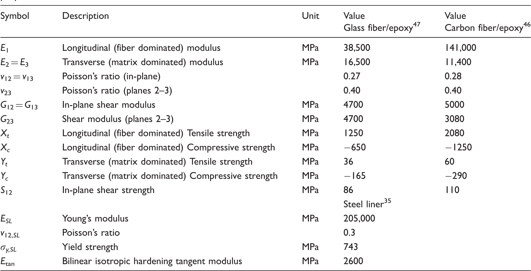
Orthotropic elastic properties and stress limits of glass and carbon fiber reinforced epoxy-based composites and isotropic properties of the steel liner.
Composite layer orientations were configured as described in Figure 4 and Table 1. To simulate helical winding, a composite layer divided into homogenized ± angle plies of winding. The single ply thickness for helical and hoop plies was chosen as 0.2 mm in accordance with the average of measured values from manufactured COPV prototypes (Table 1).
A schematic illustration of COPV configurations: (a) GF COPV and (b) hybrid COPV, featuring thickness variations due to filament winding manufacturing at the front dome section.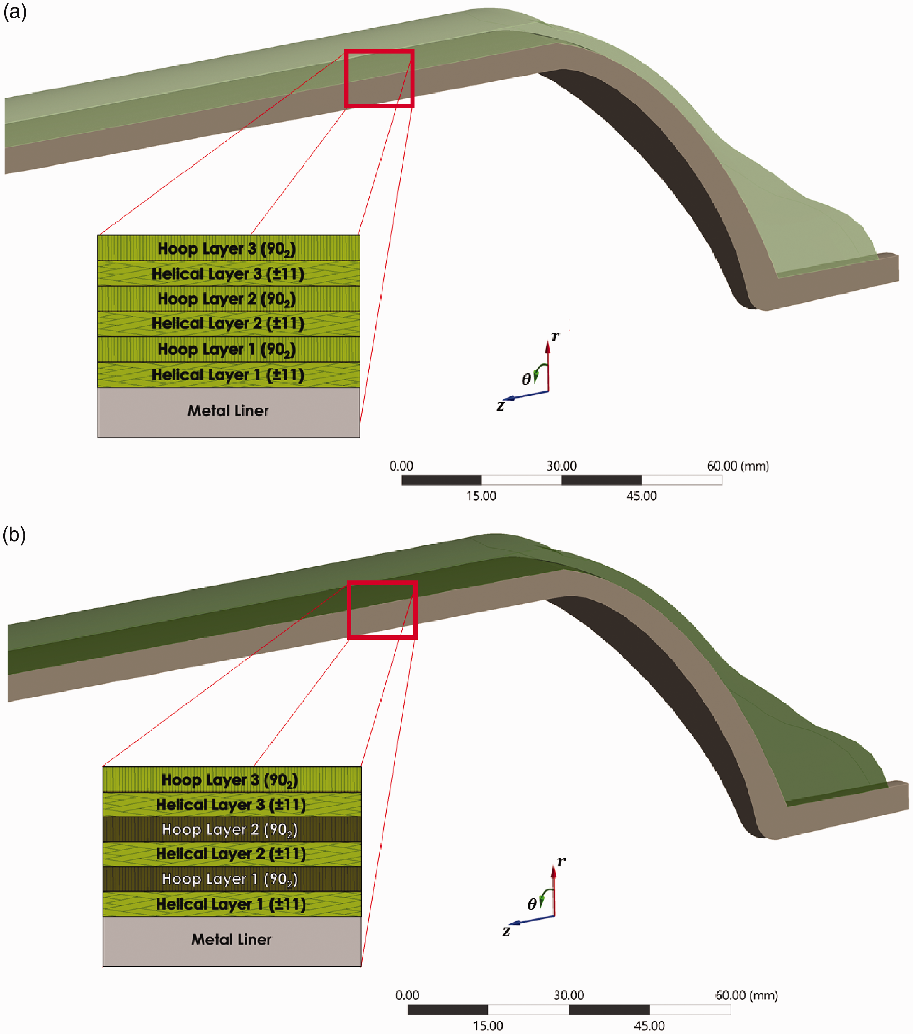
The hoop region defined for the cylindrical section of the model as hoop winding covered only the cylindrical section of the liner in filament winding manufacturing. The thickness and angle variations in the filament winding process were defined to the model based on the data obtained from CADWIND filament winding simulation, utilizing draping features available in ANSYS ACP Pre-module. The change of thickness of composite plies with respect to the nominal thickness (cylindrical section) and the angle differences occurred in the dome sections with respect to helical winding angle are given in Figure 5.
Thickness and angle deviations through the axial distance of the COPV.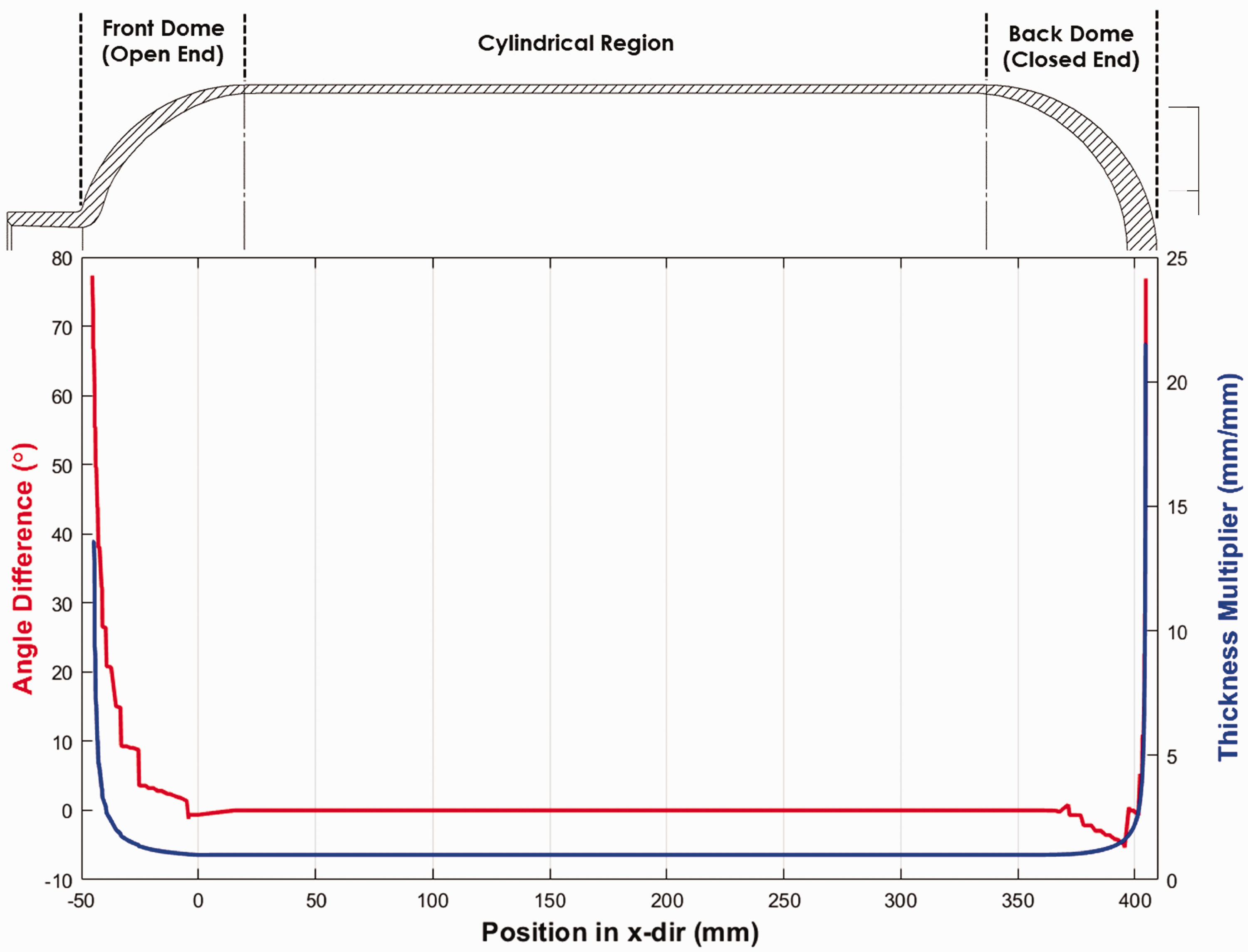
Similar to the metal liner, eight node solid hexahedral elements (SOLID185) were chosen for modeling overwrapping composite layers to evaluate 3D stress states of the composite section. A perfect bonding at the liner/composite shell is considered for all FE simulations.
In order to decrease the amount of computing time due to the complete 3D eight-node hexahedral modeling, and acquire a uniform mesh, the full vessel model was reduced to 1/16 by exploiting the axisymmetry in θ-dir. For the sectioned walls of the liner and composite layers in 1/16 model (sectioned composite and liner faces A and B shown in Figure 6), the rotation in θ-dir was restricted and displacement in r and axial (z) direction set as unrestricted. The surfaces, which were in contact with the testing apparatus, were set as fixed faces (fixed face A and B).
Boundary conditions for COPVs (a) left view (b) front view.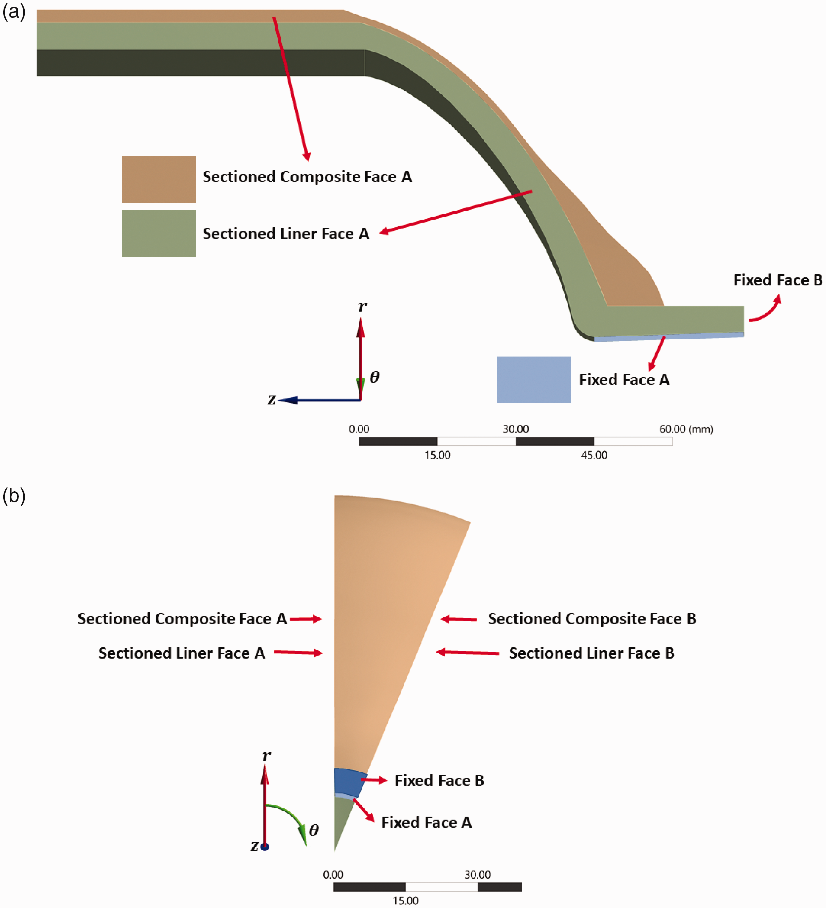
A comparison with the full model was also performed for axial and radial deformations of the liner in order to validate the boundary conditions of the reduced 3D model. It was seen that the displacements in critical regions for both models showed a negligible difference (in the order of 10−5 mm displacement). A mesh convergence study was also performed to achieve the optimum mesh size for increasing accuracy and optimizing computing time. The result of the study revealed that a 5 mm average element edge size is the optimum value for both liner and composite layer modeling for in-plane direction. In thickness direction, each composite ply is represented by an element which has a thickness of 0.2 mm. Furthermore, it was confirmed to have at least three elements through the thickness for the liner meshing. The final 3D model consists of 12,194 nodes and 11,467 elements (including bonded contact elements between the liner and composite layers). The final 1/16 COPV 3D model with a mesh structure is shown in Figure 7.
1/16 sectioned 3D model of typical COPV.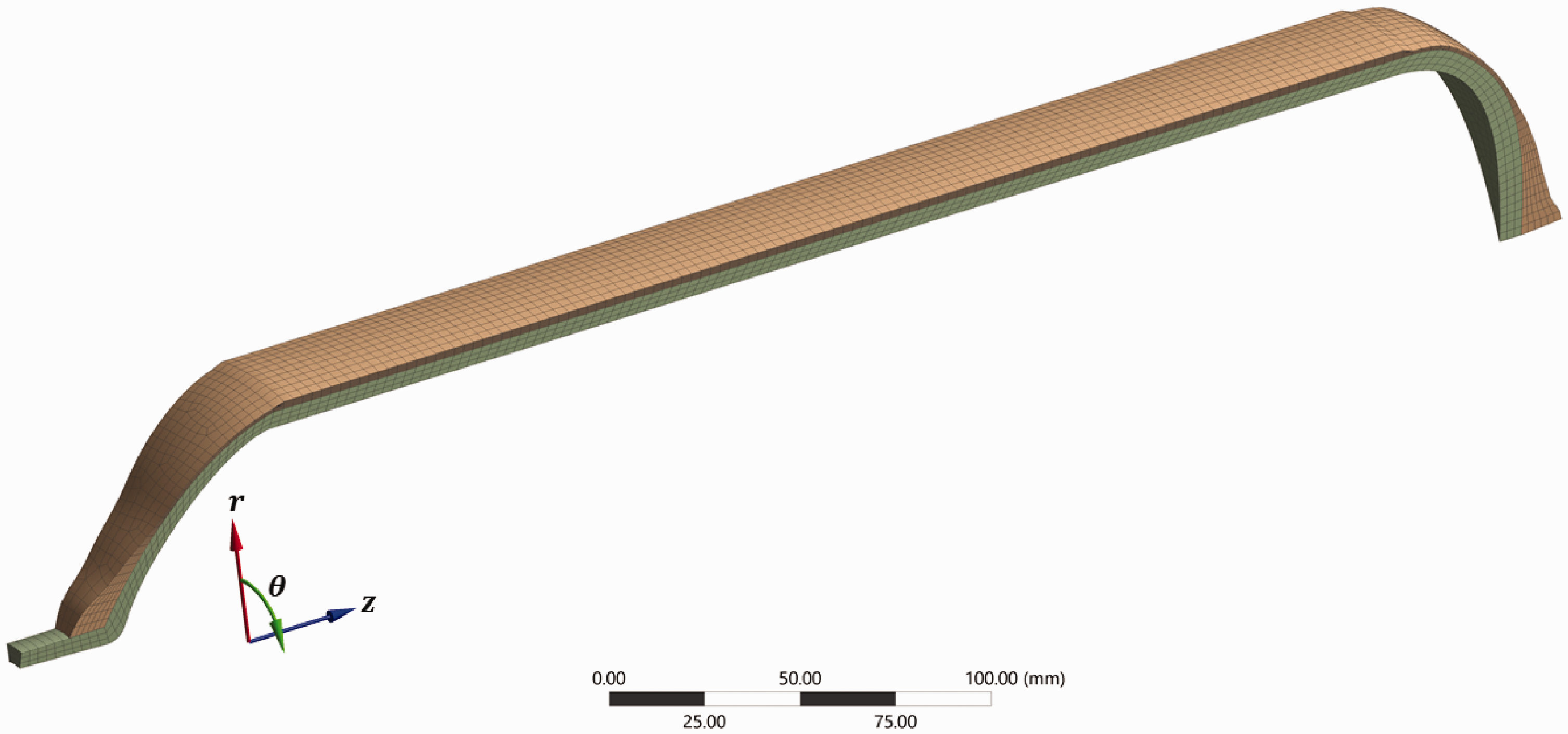
Following the onset of damage, material stiffness reduction occurs immediately. The constitutive relationship for a damaged material is given as in equation (1), where σ is the effective stress and ɛ is the total elastic strain

The damaged stiffness matrix (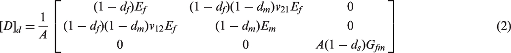
where A is defined as in terms of undamaged Poisson's ratio and fiber and matrix dominated damage variables (equation (3))

Four damage variables (one for each failure mode) are utilized to measure damage. The fiber and matrix dominated direction damage variables for calculating the damaged stiffness matrix are determined as in equations (4) and (5)


The shear damage variable 
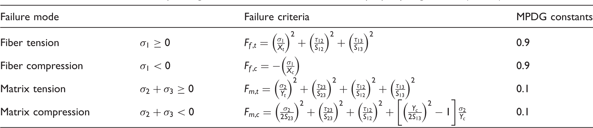
A simple progressive damage model which involves an instant reduction in mechanical properties was adopted to simulate the damage evolution in composite plies. This method, also referred as material property degradation (MPDG) in ANSYS, is compatible with 3D solid elements and the Hashin failure criterion. This model is similar to ply discount method except for the fact that the amount of degradation differs within a range between 0 and 1 for each failure mode.50,52,54 It was assumed that a failure in the fiber dominated direction occurs due to failure of the fibers, and this results with catastrophic fracture or complete material degradation. Consequently, this causes a massive instant reduction in the mechanical properties along the fiber direction. Therefore, the value of 90% reduction of the mechanical properties was selected to assign the failure in the fiber direction. Compared to complete reduction of properties, this approach (90% reduction) improves solution convergence, thus creates opportunities for observing deformational behavior of the vessel near burst. Unlike to the fiber direction, the degradation in matrix dominated direction (transverse to fibers) begins at the early stages of the loading process. In contrast to failure along the fiber dominated direction, the degradation in matrix dominated direction associates with matrix cracks and this causes a minor reduction in mechanical properties. The selected values for each failure mode in this FE model were tabulated in Table 3.
Large deformations were expected as it was intended to observe the post-yielding behavior of the liner material, so non-linear geometry setting was enabled in the FE analysis software. The displacement as the loading condition was applied linearly up until final time of 1 s with three different timestep regions. These timestep regions were defined as 0.05 s up to 0.45 s, 0.00125 s between 0.45 s and 0.75 s, and finally 0.0001 s until the last converged timestep. It was intended to gradually reduce the timesteps for improving the convergence of the numerical analysis and higher resolution of mechanical behavior through the large deformation region.
A ply-by-ply failure analysis was conducted for determining the burst pressure. The internal pressure that the last ply of the composite reinforcement occurred was determined as the burst pressure of the vessel. This phenomenon generally observed at the end (or nearly at the end, depending on the applied MPDG parameters and parameters that affect convergence) of the last converged solution of FEA.
Results and discussion
Burst pressure test results (experimental)
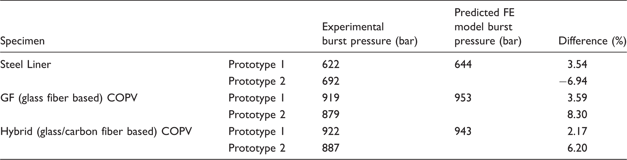
The experimental test results and numerical predictions of the burst pressure values.
The burst failure modes of all the pressure vessels tested are illustrated in Figure 8. It was evident that the final rupture occurred at the cylindrical section, and a safe burst mode was reached.
(a) Steel liner, (b) glass fiber COPVs, (c) hybrid fiber COPVs after burst pressure testing.
Acoustic measurements performed during hydrostatic testing revealed that matrix cracking developed first in the composite parts. The fiber breakage occurred predominantly on the hoop layers, presumably due to the larger strains measured on the hoop direction. The final rupture was observed on the liner, as soon as it reached a macroscale failure of the reinforcing composite layer.
Comparison of the results of experimental and FE analysis
Rosette-type strain gages were utilized to measure the local strains (axial and hoop) in the above-mentioned positions (Figure 3). The comparison of experimental and FE model predictions (the hoop and axial strain values at the strain gages located at the front, central, and back cylindrical section of the vessels) is shown in Figures 9 and 10, respectively. The results indicated that there is a satisfactory agreement between experimental and numerical strain values, especially in the hoop direction. In general, a stiffer response was observed from hybrid vessels as expected. Strain gauge measurement distortions were observed significantly along the axial direction as compared to those from the hoop direction. This may be due to an order of magnitude smaller strains in the axial direction and strain gage sensitivity. The attachment of the axial strain gauges between the outermost hoop rovings may also contribute to the observed distortions.
Comparison of experimental and FEA prediction of hoop strain values of glass fiber and hybrid COPV at (a) front (T1), (b) central (T2), and (c) back (T3) cylindrical section positions. A comparison of experimental and FEA prediction of axial strain values of the glass fiber and hybrid COPV at (a) front (T1), (b) central (T2), and (c) back (T3) cylindrical section positions.
The radial and axial deformation vs. internal pressure curves were plotted for all types of vessels in order to determine the burst pressure based on FEA as shown in Figures 11 and 12, respectively. The investigation of the metal liner behavior revealed that the liner apparently yielded at about 644 bar and then a significant radial deformation was observed. The yield point of the bare liner can also be considered as the lower burst limit of the bare metal liner due to the absence of any additional reinforcements to keep the liner intact. The behavior of COPV distinctly differentiated from the bare liner since its liner yield occurred at higher internal pressures (679 bar for glass COPV and 715 bar for hybrid COPV). After yielding of COPV liners, composite reinforcement was the sole responsible for resisting the internal pressure, which is observable from the change in the linearity of radial deformation.
The radial deformation vs. internal pressure curves of pressure vessels, obtained from FEA. The axial deformation vs. internal pressure curves of pressure vessels, obtained from FEA.
The deformation behavior of COPV, also denoted as hybrid COPV radial deformation, was significantly smaller than those for the glass COPVs at the same pressure, which is an indication of a positive hybridization effect. COPV burst pressures were measured as 953 bar for glass-based COPV, and 943 bar for glass/carbon-based COPV. Both experimental and numerical findings indicated that no hybridization effect was present for the burst pressure of the vessels (Table 4).
The result of FE analysis showed that axial deformations of the bare metal liner and COPVs differ significantly. After yielding of the bare metal liner, the axial deformation continued to increase up to 718 bar. After that point, the deformation of the bare liner dominated by the radial deformation and began to contract axially. This may not occur during the hydrostatic pressure experiments due to the fact that the final burst pressures of bare metal liners did not exceed 692 bar. For bare metal liners, the lower (yielding) and upper (axial contraction) limits of burst pressures can be identified as 644 and 718 bars, respectively. COPVs did not show any contraction behavior. This is owing to the perfectly bonded composite reinforcement in the FE model, as the composite reinforcement resists any expansion or contraction. Only glass helical filament wound layers reinforce both types of COPVs on axial direction; therefore, the axial deformation behavior of both glass and hybrid COPVs were observed as nearly identical as expected. Similar to the radial deformation curves, burst pressures of COPVs can also be detected from axial deformation behavior, for axial deformations increase steeply without any increase in the internal pressure.
Figure 13 reveals the maximum equivalent (von-Misses) stress throughout the liner with increasing the internal pressure. The composite reinforcement effect can be realized as lower stresses were observed in COPVs compared to the bare metal liner, particularly at the linear region of the curves. Figure 13 depicts the maximum stress of the whole liner through the burst pressure test. The exact location may change with increasing pressure, for instance, the maximum stress may occur in the frontal dome at lower internal pressures and in the central cylindrical section at near burst pressures.
The maximum equivalent stress of the liner vs. internal pressure curves, obtained from FEA.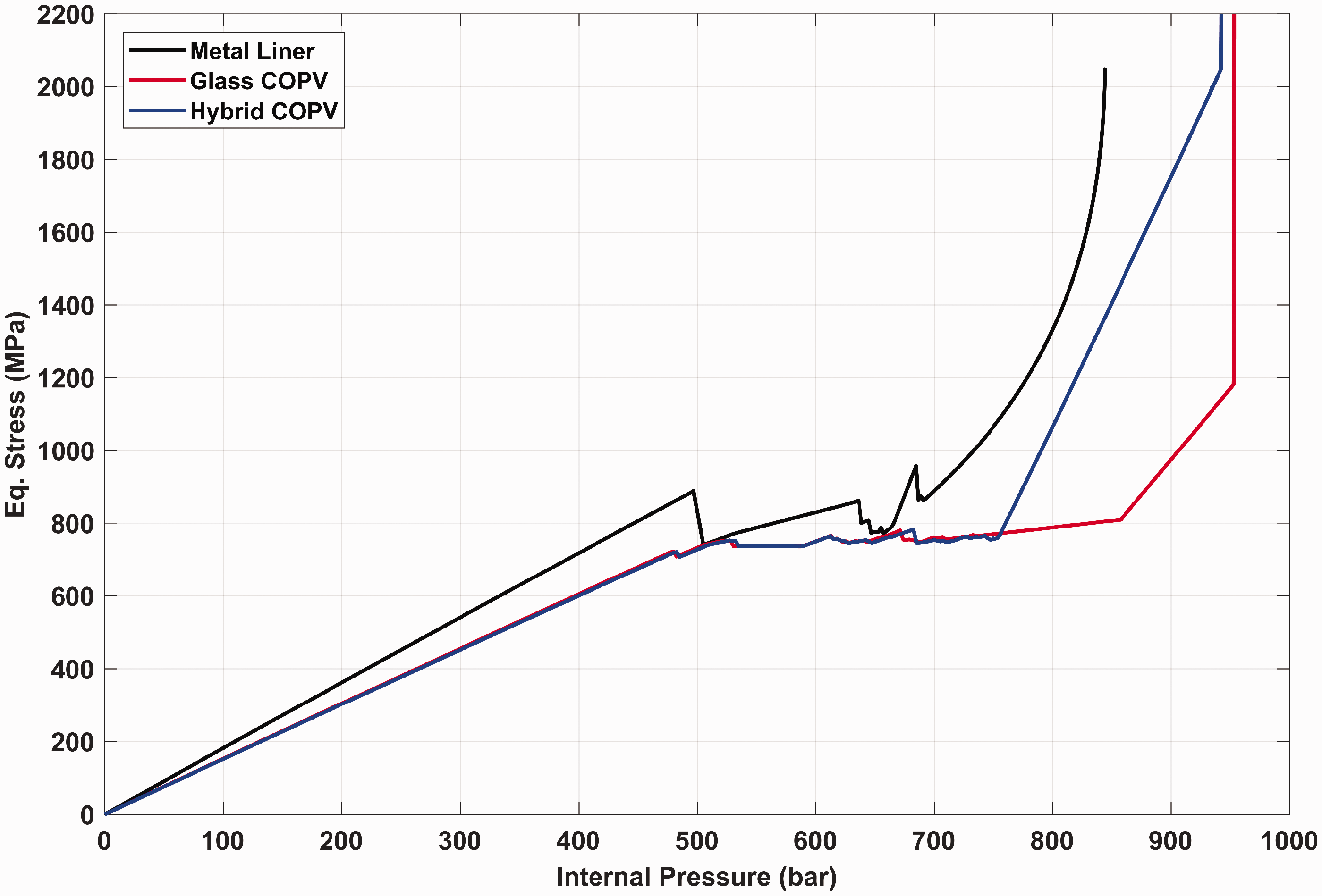
So in order to further investigate the mechanical behavior of the vessels, the equivalent stress through the inner surface of the liner is obtained from FEA at internal pressure levels of 500 and 700 bar and plotted in Figure 14. Before yielding of the liner (Figure 14(a)), the highest stresses occur at halfway through the frontal dome section. The effect of composite reinforcement was apparent on stress concentrations at the frontal and back domes and through the cylindrical region. It was also observed that the hybridization of composite hoop layers further contributes to lowering the stress of the cylindrical section of the vessel.
The equivalent stress vs. axial distance along the inner surface of the liner at (a) 500 bar and (b) 700 bar.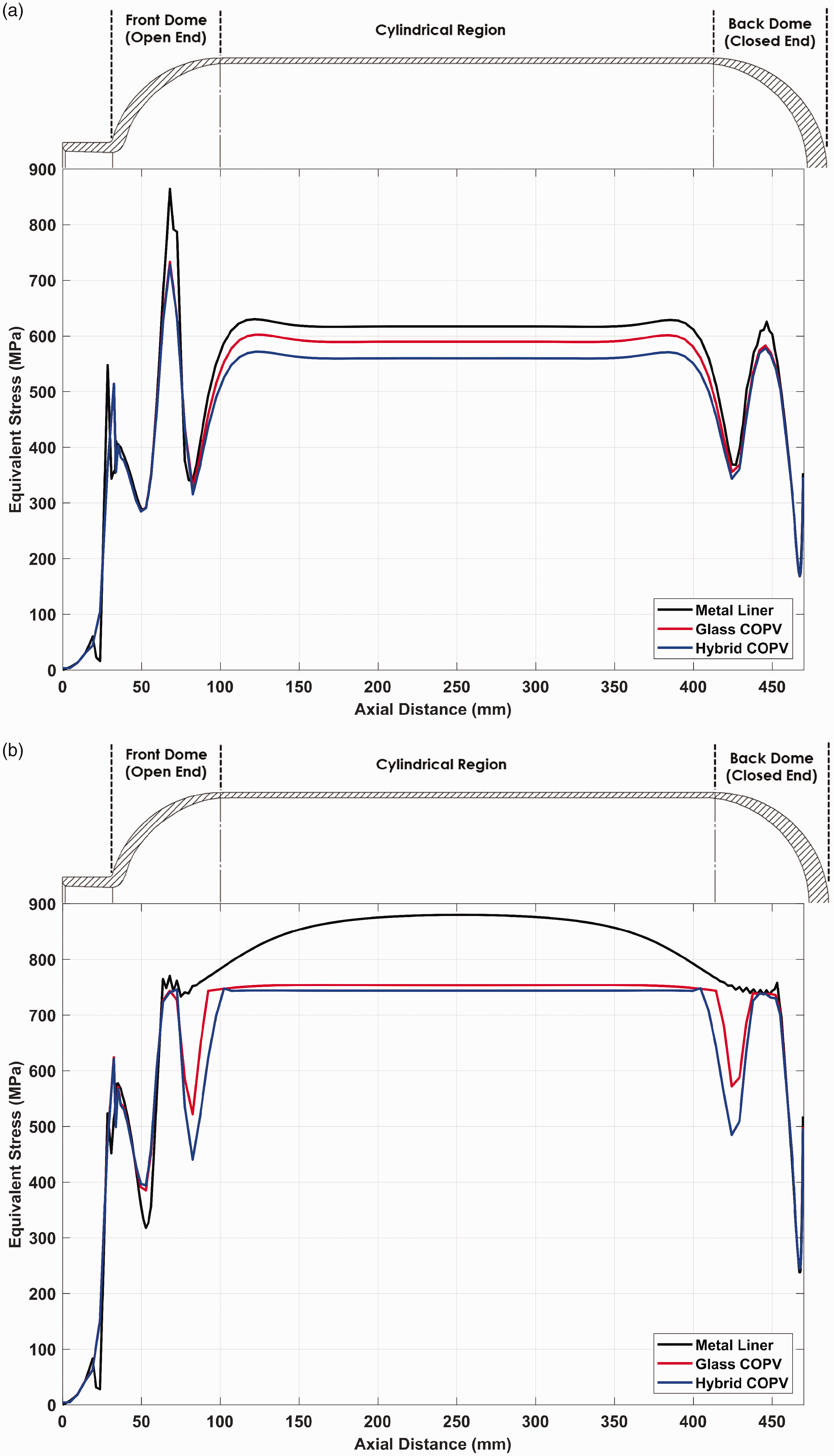
The maximum stress was reached at near burst (Figure 14(b)) cylindrical region, as expected. The bare liner showed the highest stresses at the central section of the cylindrical region owing to the fact that it has no composite reinforcement. COPVs exhibit similar behavior because of the fact that the liner has significantly low load-carrying capability, and that it reached maximum stress plateau through the cylindrical region of the vessel.
The experimental results and numerical predictions with their respective differences of the burst pressure of the produced vessels and the liner are given in Table 4. It is obviously seen that constructed 3D FE model with the Hashin FPF criterion and simple progressive failure predicts in a range within about 8% of the experimental findings. The results of the numerical prediction were slightly higher (except for the bare metal liner prototype 2, which was still in the previously identified upper and lower burst limits) in all cases. This may be associated with material inhomogeneities such as porosity and manufacturing issues that were not considered in the numerical model. Furthermore, the mechanical properties of all the materials involved in COPVs were obtained based on the information present in the literature and the data may not perfectly be representative of the manufactured COPVs. These explain the slight overestimation of the burst pressure of the vessels as compared to those obtained with the numerical model.
Although the hybridization of carbon hoop layers positively influences radial deformations and equivalent stress at the cylindrical section of the liner, both experimental and numerical burst results revealed that hybridization has negligible effect on the final burst pressure. This outcome can be explained by the stiffness difference between the carbon and GFs and the strain compatibility of the whole composite structure. In hybrid COPVs, due to their higher stiffness and lower elongation, the inner CF hoop layers tend to carry load first to ensure the strain compatibility, thus reducing the effective load-carrying capacity of the other plies. Figure 15 shows a comparison of calculated Hashin fiber tensile failure indices of all plies to demonstrate this phenomenon. It was evident that stress buildup in hoop plies was significantly faster than the helical plies in both types of COPVs. It was also noteworthy to observe that two CF hoop layers in hybrid COPV significantly reduced the failure indices in helical plies and the outermost GF layer.
A comparison of the maximum equivalent stress vs. internal pressure at the outermost glass/epoxy layer for both types of COPVs.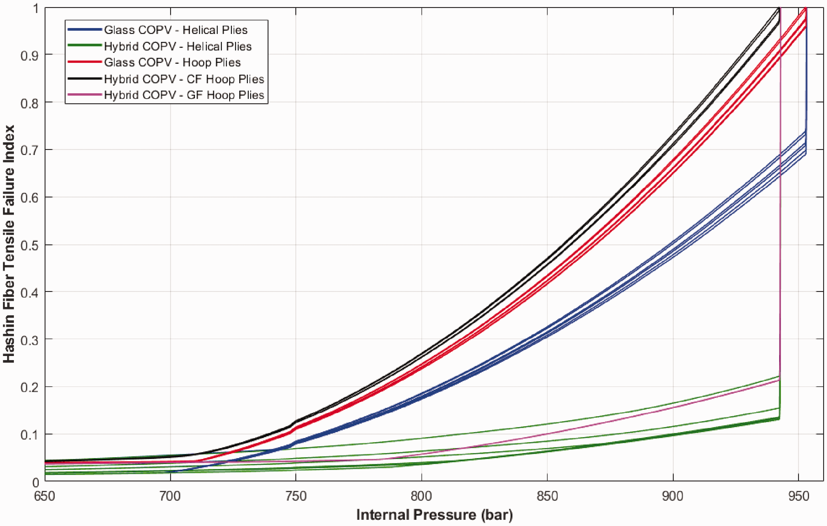
The comparison between the hoop plies of the both COPV types near burst was also made as shown in Figure 16. The progressive failure of the plies initiated when the innermost hoop ply reaches fiber tensile failure index of 1. This was followed by the sequential failures of the hoop plies from the inner to outermost direction. Finally, all helical layers immediately fail after all hoop plies lose their load bearing ability.
The comparison of failure indices of hoop plies of both COPV types near burst.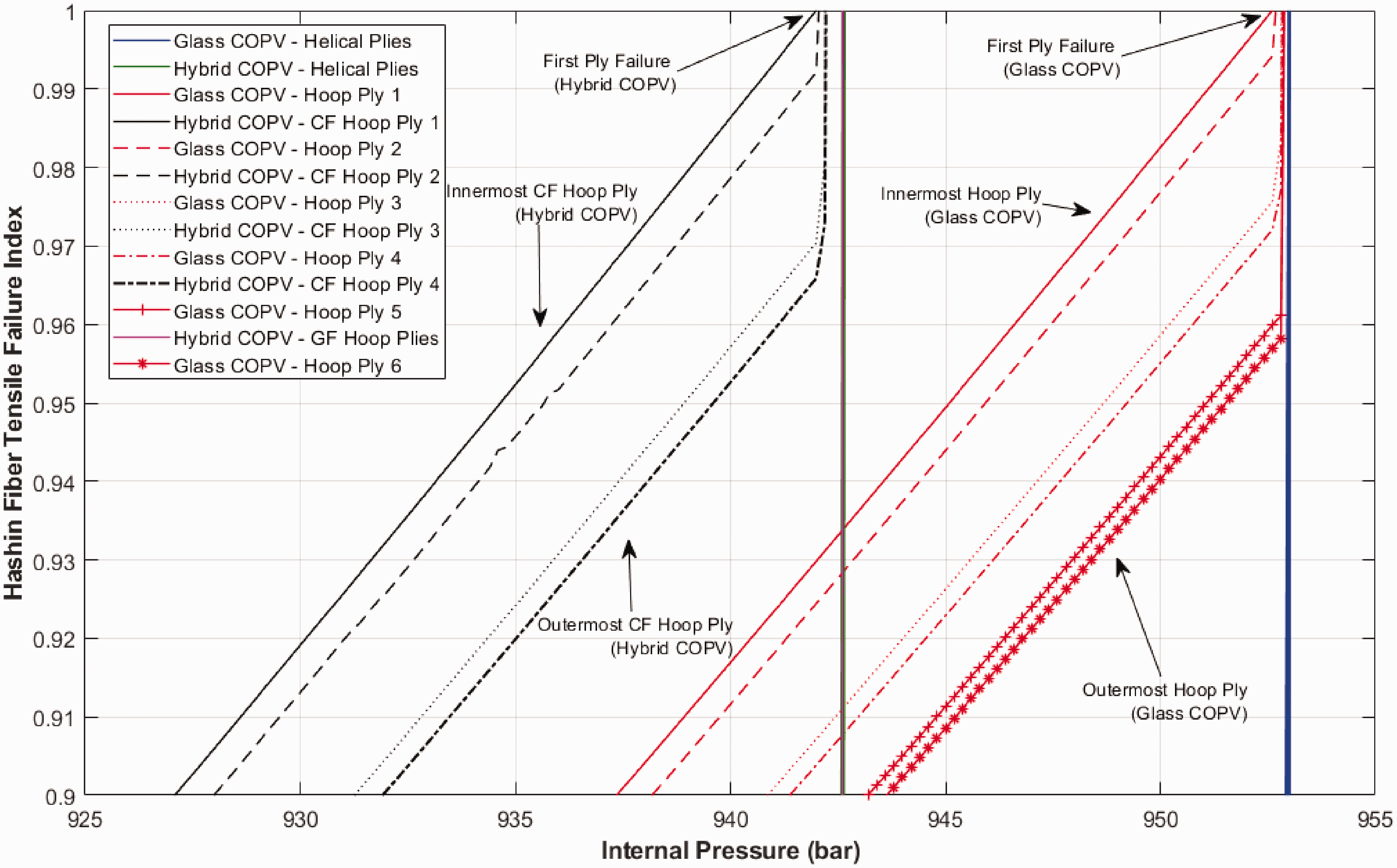
Concludıng remarks
GF and hybrid (glass/carbon) COPVs containing both helical and hoop layers were manufactured with filament winding technique. An FE model which features a non-linear material behavior for isotropic liner material, a simple progressive failure model for composite reinforcement, and thickness and fiber angle variations on the dome sections have been developed to analyze the mechanical behavior and predict the burst pressure of the vessels. The FE model yielded good correlations between experimental and numerical results. In addition to the experimental and numerical agreement of the mechanical behavior of the COPVs, the model was also able to predict the burst pressures of the vessels within 8%. However, the results showed that carbon hoop layers introduced in hybrid COPVs did not have any significant effect on the final burst pressure performance. This result was attributed to the significant increase of the load-sharing capacity of carbon fiber hoop layers due to the stiffness difference between CFs and GFs while maintaining the strain compatibility of the structure. It can be concluded that the interlayer hybridization is straightforward to implement considering both manufacturing and modeling wise with benefits in deformational behavior of the COPVs. On the other hand, it turned out to be ineffective for improving the burst performance. Furthermore, increasing the number of load-sharing carbon hoop layers at the cylindrical section of the structure may result with unsafe burst of the COPVs. As indicated in this study, the experimental validation of the numerical model featuring essential aspects of COPVs is fundamental for future development of high-pressure COPVs, thus enabling widespread adoption of alternative clean energy carriers such as hydrogen.
Footnotes
Declaration of Conflicting Interests
The author(s) declared no potential conflicts of interest with respect to the research, authorship, and/or publication of this article.
Funding
The author(s) disclosed receipt of the following financial support for the research, authorship, and/or publication of this article: This study was supported by TÜBİTAK (Scientific and Technical Research Council of Turkey) under project number 215M182. The authors acknowledge this valuable support.