
Abstract
Composite overwrapped pressure vessels (COPVs) offer significant weight advantages over traditional all-metal vessels particularly in industries like aerospace, automotive and pharmaceutical, but pose unique challenges in mechanical design, fabrication, and testing. Despite their benefits, COPVs are susceptible to stress rupture failure, which can lead to catastrophic consequences during operation. This failure mode is not fully understood, with burst pressure-induced extreme stress concentrations and dynamic loading primarily contributing to rapid deformation and strain. To address these concerns, a comprehensive investigation was conducted, focusing on optimizing and examining the effects of optimum winding angle and lay-up pattern configuration on burst pressure in vessels under internal pressure. Finite element modeling analyzed the burst pressure behavior of COPVs with a 4 mm thick aluminum core cylinder and varying layers of carbon/fiber epoxy, each with a constant thickness. ABAQUS composite modeler generated 18 COPV models with carbon fiber/epoxy plies, ensuring uniform thicknesses while exploring different fiber orientations. The effects of ply stacking sequence were analyzed through finite element analysis for all models, comprising varying layers with uniform thicknesses. Attention was paid to failure criteria, methodically evaluating the burst strength of the Al/CFRPC COPVs This exhaustive analysis yielded an optimal COPV design profile characterized by a precisely calibrated ply stacking sequence of [24.50, −24.50] PP winding pattern and six (6) arranged layers. The stress-strain distribution analysis of the Composite Overwrapped Pressure Vessel (COPV) revealed both a uniform distribution of stress across its surface and extreme stress concentration, particularly peaking towards the polar boss region. This concentration is discernible due to variations in ply thickness induced by the overwrapped fiber orientation. This investigation provides valuable insights for optimizing COPV design and enhancing its performance and reliability in various applications.
Keywords
Introduction
A cutting-edge engineering solution for the storage and transportation of pressurized fluids or gases is the Composite Overwrapped Pressure Vessel (COPV). A Composite Overwrapped Pressure Vessel (COPV) is a structural configuration where the fibers contribute to the tensile strength, while the matrix bears the shear load and a liner, which can be made of either plastic or metal, functions as a protective barrier.
1
Composite materials like Carbon, Kevlar, and glass tend to have reduced burst strength when impacted. The application of COPVs spans various industries, encompassing aerospace, automotive, energy, and defense. They play pivotal roles in spacecraft, rocket propulsion systems, and vehicle fuel storage, particularly in situations where achieving a balance between high strength and low weight is critical.
2
The manufacturing process of COPVs employs precise techniques like filament winding, automated tape layer and automated fiber placement. In filament winding, composite fibers are intricately wound around a mandrel in a specific pattern, while automated fiber placement ensures uniform strength and structural integrity throughout the vessel.
3
The filament-winding technique is the employed manufacturing method for composite pressure vessels such as cylindrical and spherical pressure containers.
4
The winding patterns can be hoop (or circumferential), helical, or polar, depending on the desired characteristics of the final product. After the winding is complete, the composite is cured, and the mandrel is removed, leaving behind a hollow and structurally reinforced composite part.
5
Figure 1, depicts the implementation of the winding procedure, wherein the subsequent curing phase occurs at a specified temperature.
6
This filament winding process facilitates the seamless creation of axially symmetric constructions. Filament winding Manufacturing methods.
The technological evolution of pressure vessels designed to contain liquids and gases under pressure has progressed through five distinct generations. The initial Type I vessels were entirely metallic, characterized by their considerable weight and limited resistance to fatigue when compared to subsequent types. Type II and Type III represent composite overwrapped pressure vessels (COPV) with metallic liners. In Type II, the cylindrical section of the liner is partially overwrapped with composite material in the hoop direction, while in Type III; the liner is fully overwrapped with composite material.
7
The development advanced further with Type IV, recognized as a full composite pressure vessel, where a polymeric liner is entirely encased in composite material.
8
The depicted Figure 2 below illustrates the typical configuration of composite overwrapped pressure vessels featuring aluminum liners and a specified count of composite overwraps. The aluminum liner functions as a protective barrier, preventing any leakage from the cylinder’s contents, participates in load sharing, specifically distributing the internal pressure load in conjunction with the composite overwraps. This type of metallic liner can be referred to as a load-sharing metallic liner.
9
General layout of COPV.
A recent innovation introduced Type V, featuring a liner-less pressure vessel designed for spacecraft applications. This novel approach eliminates the need for a liner, relying on the enhanced properties of Nano-particles within the composite matrix. This development represents a significant leap forward in pressure vessel technology, particularly in the specialized field of spacecraft applications. 10
The burst pressure of a COPV is significantly influenced by material properties such as tensile strength, fracture toughness, stiffness, yield strength, fatigue resistance, chemical compatibility, temperature resistance, density, thermal expansion coefficient, and creep resistance. The investigation by Xia et al. 11 centered on multi-layered composite cylinders experiencing hydrothermal loading, while Sayman 12 scrutinized multi-layered thin composite cylinders exposed to varying hydrothermal conditions. The authors conclude that the highest axial stress (σz) occurs under a uniform temperature distribution. In the case of a parabolic temperature distribution, both tangential and axial stress components are compressive near the inner surface and tensile near the outer surface, with the maximum stress concentrated at the inner surface. Additionally, Xia et al. explored a precise solution for multi-layered filament wound composite cylinders featuring a resin core under the influence of pure bending. Sayman et al. 13 investigated temperature and stacking sequence effects on the E-glass/epoxy composite pressure vessels under internal pressure for the generalized plane strain case. The results indicate that the orientation angle and the temperature have significant effects on the failure pressures of the pressure vessels with plastic liners and the impact of the core material on the pipe’s strength is significant when it comes to sandwich composite pipe constructions with low core strength. Roy and Massard. 14 Studied the design of thick multi-layered composite spherical pressure vessels based on a 3-D linear elastic solution. They found that hybrid spheres made from two different materials represented an opportunity to increase the burst pressure.
Adali et al. 15 investigated the optimization of multi-layered composite pressure vessels using an exact elasticity solution. The three-dimensional interactive Tsai-Wu failure criterion was used to predict the maximum burst pressure. Mirza et al. 16 studied the composite vessels under concentrated moments by using the finite element method. Sun et al. 17 calculated stresses and the burst pressure of filament wound solid-rocket motor cases; maximum stress theory and stiffness-degradation model were introduced in the failure analysis. Glass-reinforced plastic (GRP) pipes with varying orientation angles ([45°/-45°] s, [55°/-55°]s, [60°/-60°]s, [75°/ −75°]s, [88°/-88°]s) were tested, showing close results between analytical and experimental solutions. 18 Brabin, T. Aseer, investigated various predictive equations for burst pressure using test data from diverse steel vessels. They proposed that variations in burst pressure values are linked to differences in the strength properties of the vessel material. 19 In Serkan Kangal’s study, the focus was on investigating the impact of interlayer hybridization on burst pressure in composite overwrapped pressure vessels (COPVs) with a load-sharing metallic liner. Using a 34CrMo4 steel liner and glass/carbon filaments, the vessels underwent pressure testing. Both experimental and numerical analyses were employed, with the numerical model accurately predicting burst pressures within an 8% range. While hybridizing interlayers positively affected radial deformation, the hybridization of hoop layers had limited impact due to stiffness differences between carbon and glass fibers. 20
Xin Zhang utilizes a reliability-based optimal design approach, considering the thickness and angles of composite winding layers. 21 Through this method, the strength of the optimized cylinder has increased by 0.7%, all while prioritizing cost efficiency and weight reduction. Regassa, Y, explores the burst performance of a type III composite overwrapped pressure vessel (COPV) through finite element methods. 22 The author reveals that in a vertical COPV design, the maximum stress occurs along the axial direction. The researcher also utilizes finite element modeling to optimize the design of a Composite Overwrapped Pressure Vessel (COPV) featuring a 4 mm thick aluminum core and incorporating carbon fiber/epoxy plies. 23 The finding indicates [55°, −55°] PP optimum winding pattern 24 MPa burst pressure capacity.
Several researches were performed on the design optimize of composite pressure vessel. To Various research endeavors have delved into optimizing the design of composite pressure vessels. In the pursuit of determining the optimal winding angle for manufacturing such vessels, one study utilized conventional laminated plates and applied Tsai-Wu failure theories.
24
The findings indicated that the optimal inter-ply angles varied depending on the material, with values of
The research concluded that an orientation angle of α ± 45° was the most favorable among the studied fiber orientation angles. Regassa, Y utilizes finite element modeling to optimize the design of a Composite Overwrapped Pressure Vessel (COPV) featuring a 4 mm thick aluminum core. 23 Employing ABAQUS, the study generates 14 models incorporating carbon fiber/epoxy plies. The preferred design is distinguished by a [55°, −55°] PP optimum winding pattern. The ultimate load-bearing capability of a pressure vessel can be calculated by addressing interlaminar and intralaminar failure modes. 27 Tsai-Wu failure theory provides accurate numerical analysis. 28 Designs leveraging fiber tensile strength for resistance against gas-induced loads exhibit superior performance. 29 Burst pressure, like other measured variables, primarily depends on vessel material and stored content.30,31 Increasing fiber volume ratios enhance fiber strength and, consequently, burst pressure. 32 Varying winding thickness and angles as design variables can alter the burst pressure of pressure vessels. 33 Damage propagation and rupture life are highly variable under constant pressure, with significant changes in energy emission during failure. 34 Composite and liner failures are the primary burst failure modes and fiber orientation strongly influences the shape of the damaged zone. 35 The braided reinforcement configuration has the highest damage potential under static pressure. 36 Burst strength varies with changes in winding angle and layer thickness. 37 An extensive study investigated the residual strength of composite overwrapped pressure vessels under impact. Varying mechanical work levels and impact energies were tested, with computed tomography scans revealing damage. The reduction in burst pressure post-damage indicated that shear bands, formed after delamination’s, significantly decreased residual strength. 38 Fowler et al. 39 focused on damage-tolerant design and optimization of toroidal cross-sectional profiles in their review of toroidal composite pressure vessels.
Rafe and Torabi 7 investigated failure pressures, considering manufacturing uncertainties and comparing different failure criteria. Oliveira et al. 40 used a gradient-based method to update stacking orientation and ply thickness, and Daghia et al. 41 proposed a hierarchy for internal and external optimization in composite pressure vessels., considering the wind angle as shape optimization. Lin et al. 42 introduced a progressive failure analysis technique utilizing the Puck failure criterion and effective elastic parameters from Representative Volume Elements (RVEs) to explore failure modes in Type III composite pressure vessels during hydraulic burst tests. Nguyen et al. 43 developed a predictive modeling tool for analyzing damage and designing hydrogen storage composite pressure vessels. Azeem et al. 44 conducted a review on the utility of filament winding techniques for Composite Pressure Vessels (CPVs), discussing its evolution, various optimization techniques, numerical analysis strategies, and challenges. Kothali et al. 45 employed Finite Element Analysis (FEA) methods to determine the bursting pressure of Fiber-Reinforced Polymer (FRP) pressure vessels. Yenugula and Bhukya 46 conducted thermal, fatigue, and static stress analyses on cylindrical pressure vessels with different materials.
Overall, Researchers have extensively explored the burst pressure analysis of composite overwrapped pressure vessels (COPVs) through various methodologies. Despite these efforts, a comprehensive understanding of burst failure in COPVs remains elusive, contributing to frequent and severe catastrophic failures. To date, the composite stress rupture failure mode has not been fully understood, and there have been no reported instances of stress rupture failures of COPVs. Burst pressure analysis and optimization stand as pivotal endeavors in comprehending failures in composite materials, given that stress rupture often stems from the impact of burst pressure. To identify the burst pressure of composite overwrapped pressure vessels, focusing on identifying the stacking orientation that maximizes strength and minimizes ply lay-up thickness, acting loads, as well as the liner metal properties used were important parameter in the COPVs analysis. This study aims to delve deeper into the optimization of burst pressure analysis of composite overwrapped pressure vessels, employing numerical and Analytical methods and aims to recommend suitable materials for diverse applications, such as the pharmaceutical, automotives and aerospace industries, based on the findings of the study.
Materials and methods
Material property of AL6061 Aluminum and (CFRP) (T800S/Epoxy).
Analytical study of COPV based on netting analysis and isotensoid theory
The semi-geodesic route equation for filament-wound structures includes the slippage parameter to address and factor in this phenomenon.

Where,
Slippage occurs when fiber filaments encircle the mandrel in a manner that allows them to move in a direction other than along the extension of the fiber axis. It is advisable to wind the filament in a geodesic route along the mandrel’s surface. A geodesic path or curve represents the shortest distance between two points on a curved surface. Opting for the geodesic path is ideal because it eliminates fiber slippage throughout the component. The geodesic arc profile on a right circular cylinder conforms to an arcsine function, representing a segment of a circular helix. This definition is instrumental in filament winding as it ensures that fibers follow the most direct route between any two points on the mandrel surface. The stability of the geodesic arc’s trajectory is noteworthy, compelling fibers to stretch if they deviate from the prescribed course. However, adhering strictly to the geodesic path when winding the cylinder’s ends is impractical. A change in winding direction becomes necessary to complete a full layer, introducing a departure from the geodesic path to secure fiber placement through friction. Figure 3.3 presents a schematic depiction of the geodesic path on a cylindrical surface and geometric illustration of a pressure vessel dome. 47
The geodesic fiber path can be determined by setting the fiber slippage parameter, Schematic illustration of geodesic path on a cylindrical surface (a) and geometric illustration of a pressure vessel dome (b).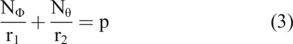
Using the fibers ultimate tensile strength to transform stress from the direction of the fiber route-winding angle to the meridian and circumferential direction, 

The condition of filaments lying along geodesic pathways hold when:
Equation (8) imposes the restriction on the winding pattern, ensuring that fibers across the spherical shape follow paths along the sphere. Consequently, the determination of the winding angle at any given point x along the dome counter can be established using the following procedure.
The geodesic dome contour of the vessel is then established by changing the dome geometry and determining the associated y position of the radius values x. The meridian and circumferential radius are connected in the first place by: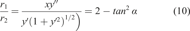
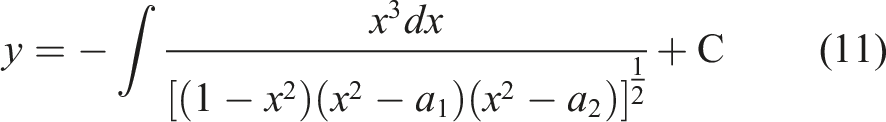
The requirement that y equals zero when x is equal to one is employed in the calculation of the integral variable C. The determination of the geometry of the dome route is achieved by integrating equation (11). The identification of the winding point is elucidated concerning the strands and shell specifications, encompassing both geodesic and non-geodesic winding approaches, as depicted in equation (12). The following part of the text explores the methodology of non-geodesic winding.
8
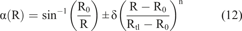
The power n is a deviation from the turnaround points, as n approaches to infinity winding angle approaches the geodesic value.
49
An algebraic function following the geodesic path generates a shell on rotation about the meridian, which is called isotensoidal shell. If any fiber is stretched by equal tension, constant fiber tension can guarantee a production process by avoiding fiber slip off. This condition as shown equation (13) is known as the Clairault condition.
50

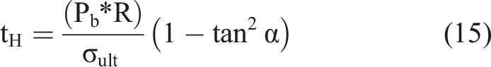
The thickness of the polar (
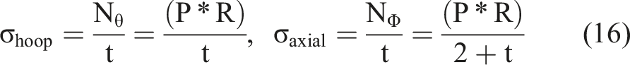
Axial and circumferential stresses can be found in equation (16).
51
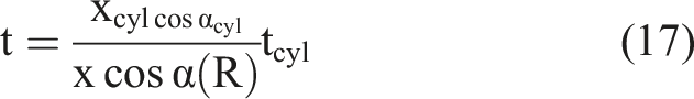
The thickness of the fiber-wound reinforcement at every point along the curvature is obtained through.
51
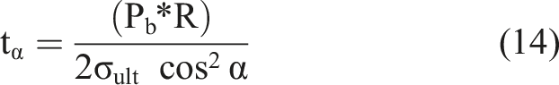
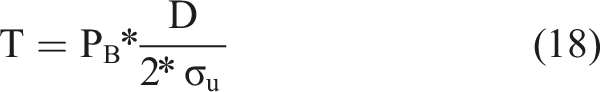
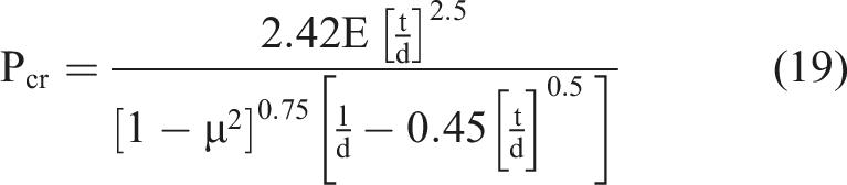
The liner has to be designed for the maximum burst pressure capability near the pole, to meet the requirement Barlow’s equation (18) is used to obtain the thickness of the cylindrical shell.
50
Failure modes with corresponding Hashin’s failure criteria and material property degradation (MPDG) constants. 20
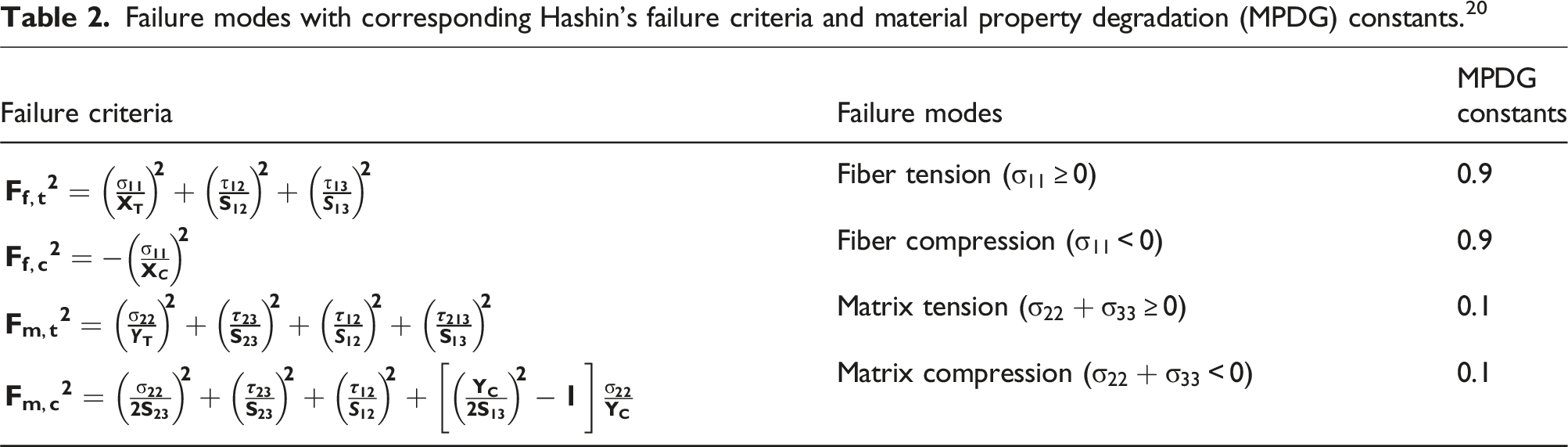
Other Failure criterion used in burst pressure analysis of composite overwrapped pressure vessel was maximum strain, maximum stress, Tsai-Hill and Tsai-Wu failure criterion. Since this failure criterion are well known the detailed failure criterions are not given here. This four-failure criterion with Hashin’s failure criterion are used in burst pressure analysis of COPV and compares the results.
Finite element modeling of the vessel
The finite element analysis model was created using the exterior surface of the liner as the reference for the mandrel surface, establishing the winding geometry. The overall geometric configuration of the inner liner of the studied pressure vessel was established following the ASTM D 2585 Composite overwrapped pressure vessel.
The pressure vessel is constructed with specific dimensions, featuring a length of 241.3 mm and a diameter of 146.05 mm. It incorporates an inner layer made of ASTM (AL6061) Aluminum layer that is 4 mm thick. Employing dome shape estimations, the vessel’s geometry was then visually represented through plotting. However, it is noteworthy that developers have the option to define such geometry post-CAD modeling by importing it as a part drawing using the provided analytical data. Subsequently, a finite element analysis was conducted using the ABAQUS standard/explicit model. The model of the Composite overwrapped pressure vessel was generated utilizing the composite modeler feature within the ABAQUS software, following the steps outlined in Figure 4. Given the y symmetry of the structure, material properties, and internal pressures of the composite pressure vessel, a quarter of the finite element model (swept over 90°) was established employing a cylindrical coordinate system in ABAQUS. Flow chart analysis steps and iteration techniques used in ABAQUS/CAE composite modeler.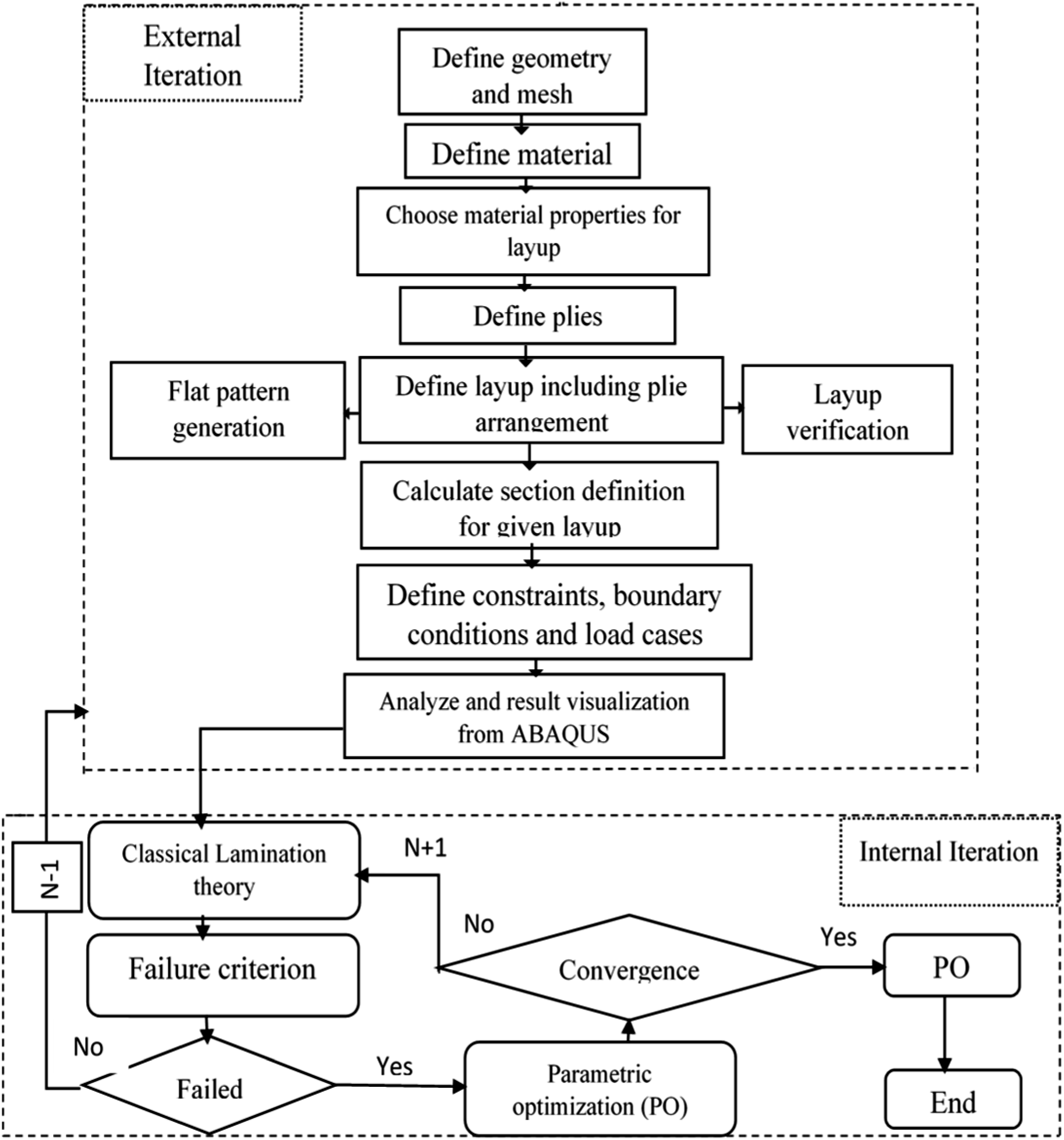
Furthermore, the ABAQUS/CAE package was utilized to create the geometry of the pressure vessel, incorporating the load-sharing metallic liner and the composite overwrap. This method is rational and effective in representing the symmetrical attributes of the pressure vessel while maximizing the efficiency of computational resources. The liner geometry model (creation of an axisymmetric component) is given in Figure 5 which was modeled through the ABAQUS modular. The model of the COPV vessel was generated utilizing the composite modeler feature within the ABAQUS software, following the steps outlined in Figure 4. Once the input parameters are defined, the Finite Element Analysis (FEA) process proceeds as an external iteration. In this step, the model is subjected to internal pressure, and the resulting stresses and strains are calculated. To evaluate the force distribution around the cross-section along the y-coordinate, a symmetric boundary condition is applied to the FE model. The critical membrane forces, including normal and moment forces along the axial coordinate, are extracted and subsequently used in the Classical Lamination Theory (CLT) analysis, which incorporates failure criteria. The internal loop of the optimization process aims to minimize the weight/strain in the laminate by updating the stacking orientation. Once the results converge to the optimal point, a ply is removed, resulting in a stacking sequence with N-1 layers, as illustrated in Figure 4. This loop continues until no new feasible solutions are found, and the final feasible solution with the optimal number of plies and their stacking sequence is obtained. Inner Liner Model of (AL6061) Aluminum layer.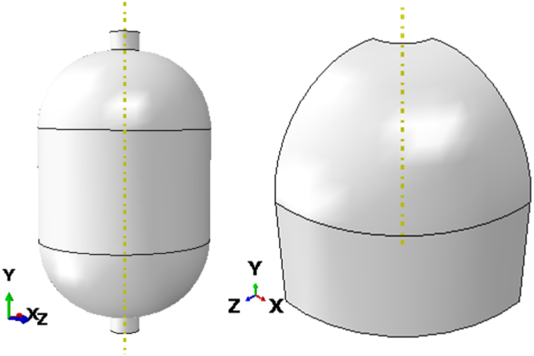
The optimization involves iterating different values for the winding angle θ and number of layers N. After performing these iterations, the optimal configuration was determined to be a winding angle of θ = ±24.5 and N = 6 layers. At this configuration, the vessel achieved a burst pressure of 25 MPa effectively minimizing the number of layers (and thus the weight) while meeting the required performance criteria.
The ABAQUS/CAE software was used to input material properties and manipulate parameters in a finite element model, varying the number of layers, layer sequence, and orientation. Figure 6 illustrates the fiber orientation in the Composite Overwrapped Pressure Vessel (COPV). Arrangement of fiber orientation and stacking sequence.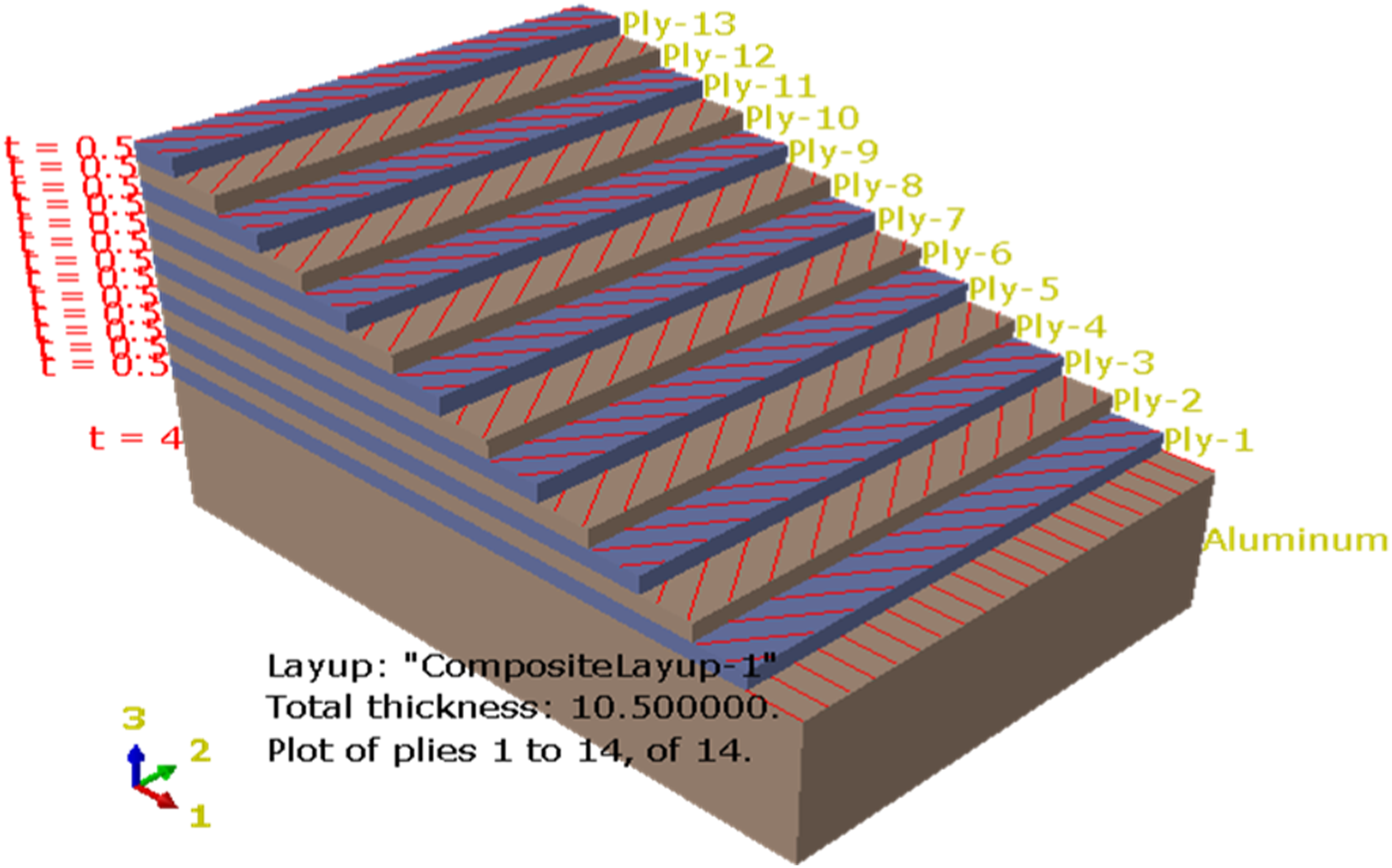
Composite overwrapped pressure vessel was created with the liner and fully overwrapped T800S carbon/epoxy composite using ABAQUS/CAE module. The physical and mechanical properties of the liner and composite layer used in the analysis were presented in Table 1. Static structural model was carried out based on based on the finite element with ABAQUS/CAE software. Non-linear geometry was considered in all cases to handle large and unbalanced deformation. The mesh generation process in ABAQUS/CAE was conducted meticulously, emphasizing both computational efficiency and accuracy through thorough mesh convergence analysis. By systematically adjusting element sizes, an exhaustive study was undertaken to identify the most suitable mesh configuration, complemented by the selection of the S8R element type for added robustness. After meticulous analysis, a finely tuned model comprising 45,968 elements was determined as the optimal choice for further examination. Boundary conditions were meticulously applied to ensure adherence to real-world conditions, including precise fixation of radial and circumferential displacements on the top face using a local cylindrical coordinate system, and strict enforcement of symmetry boundary conditions on the lateral surfaces to maintain structural integrity. Subsequent loading scenarios were methodically introduced to induce stresses and deformations, with analytical models meticulously considering intricate material properties and geometry for precise response predictions.
The procedure of modeling the vessel from equation (1) to equation (11) follows the following procedures: • Start with the geometry of the COPV. This typically involves defining the shape of the vessel. • Use a parametric equation to describe the surface of the vessel, which will serve as the basis for the fiber winding paths. The winding angle (α) is the angle between the fiber path and the axial direction of the vessel. • Use the differential equation (1) to equation (11) to describe how α changes along the length of the vessel. The equation can be integrated numerically to obtain α as a function of z. • Implement the winding path in a simulation or CAD software by generating the fiber paths based on the calculated α values. Tools like SolidWorks or ANSYS Composite PrepPost could be used. • The initial conditions at the start of the dome (where it connects to the cylindrical section) will affect how the winding angle evolves. • Visualize the winding pattern on the dome. The winding should show a gradual change in angle, possibly tighter near the base and more relaxed near the apex. The fibers will be laid down with varying angles as it move from the base of the dome to the apex.
The image shows the fiber winding pattern with varying angles, highlighting how the winding becomes tighter near the base of the dome and more relaxed towards the apex. This helps how the winding angle equation specifically to the dome section of COPV model applied.
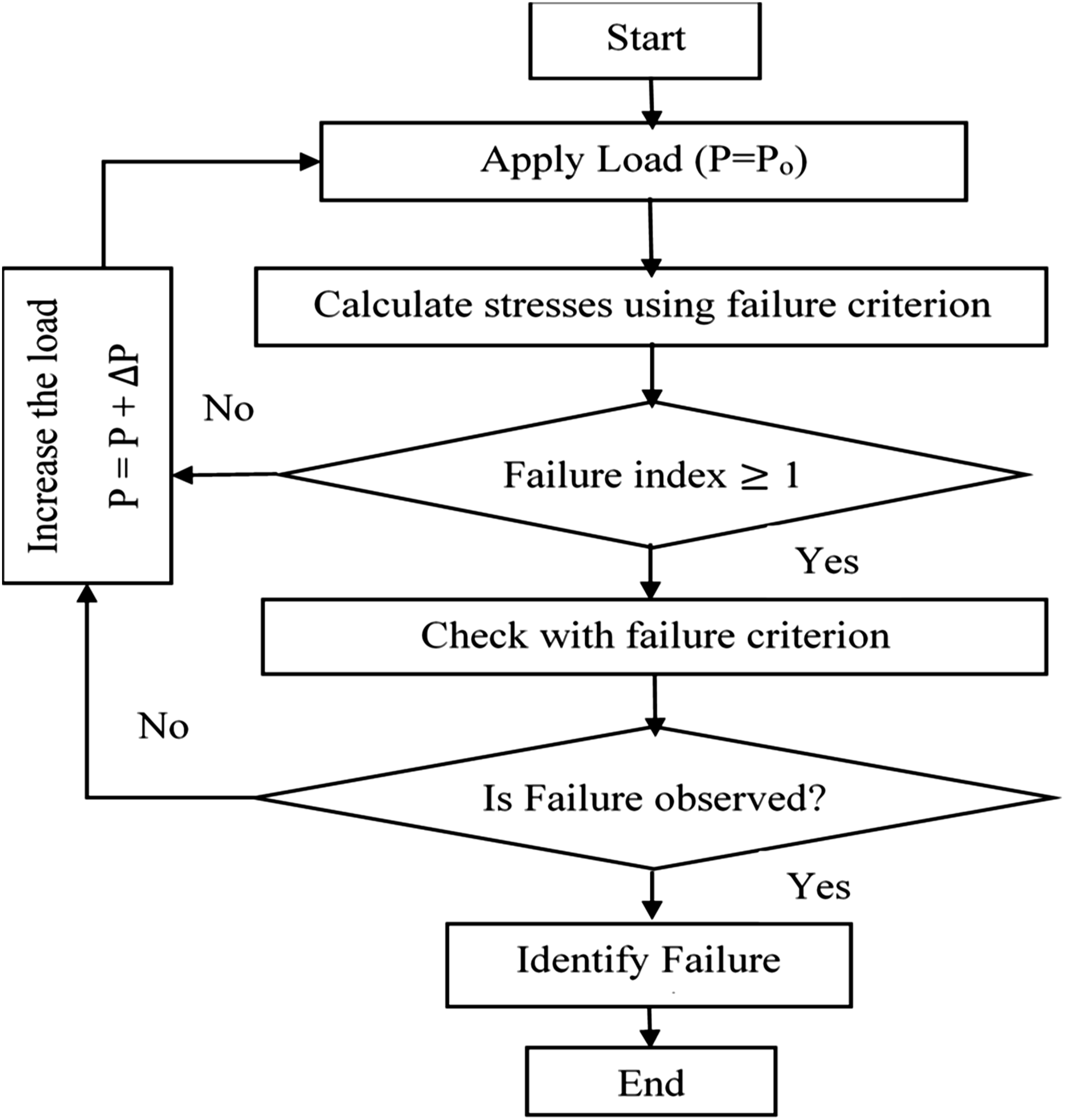
The primary objective of the study was to optimize and comprehensively evaluate the impact of varying winding angles and lay-up patterns on the burst pressure of vessels under significant internal pressure of 30 MPa. The computational examination of the developed model delved into the impact of fiber orientation and laminas quantity across 18 COPV models. Multiple criteria, encompassing maximum stress and strain, Tsai-Hill, Tsai-Wu, and Hashin’s damage criterion, were employed to determine the burst pressure for each COPV. The applied load served as the threshold for failure, identified when the failure index surpassed one. Figure 7 illustrates the rigorous approach adopted to assess prevalent failure criteria in this study (Figure 8). Visualization of the composite overwrapped pressure vessel with the fiber winding pattern. The process flowchart for verifying failure criteria.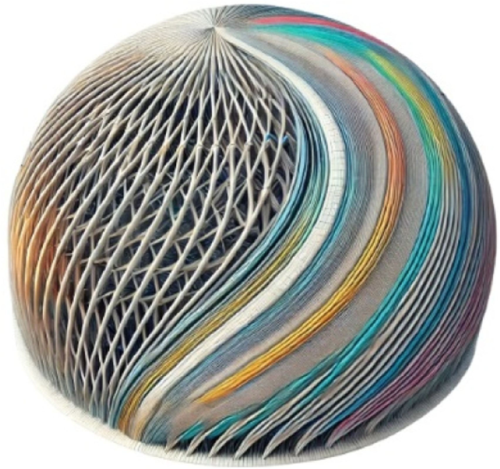
A gradual application of internal pressure, increasing incrementally, up to 30 MPa was employed. The subsequent six models (models 6–11) were scrutinized by altering the number of layers while maintaining a constant orientation angle for Al/CFRPC across all models, the CFRPC composite thickness remained consistent at 6.5 mm found analytically.
Results and discussion
A three-dimensional shell model of the vessel was created using ABAQUS/CAE, adhering to ASTM D2285 specifications. The initial composite shell had a total thickness of 6.5 mm for aluminum/carbon fiber reinforced plastic (Al/CFRP) The S8R element type was used for mesh creation. To determine the optimal burst pressure, the total ply thickness, ply angle, and number of plies were all optimized. The simulation identified the optimal configuration for Al/CFRP as six (6) plies with a ply angle of [24.5°/ −24.5°] s degrees.
Burst pressure analysis
The COPV’s burst pressure, determined through the failure increment step, involved the application of internal pressure in gradual increments. The calculation of the burst pressure relied on the failure pressure step, expressed by the equation: Burst pressure = (maximum target pressure set) multiplied by (failure load step). The discussion on the failure index utilized for each theory in the optimized model is outlined accordingly. The Maximum Strain Failure Indexes (MSTRN) are depicted in Figure 9(a) and (b), corresponding to step times of 0.8125 and 0.8629, respectively. Figure 9(b) reveals that at the 0.8629 step time, there are instances where the maximum strain values exceed one (1) in the large hoop area. Therefore, this specific step time increment is identified as indicative of burst pressure indexes. The burst pressure calculated at this step time is (0.8629 * 30 MPa) = 25.887 MPa. The figures portray Maximum Stress Failure Indexes (MSTRS) at step times of 0.8758 and 0.925 in Figure 9(c) and (d), respectively. In Figure 9(c), the stress failure index consistently remains below one across the entire model, making the failure index inconsequential for this load step. In contrast, Figure 9(d) reveals stress values surpassing one (1) in the large hoop area at the 0.9375step time. As a result, this specific load step increment is considered indicative of burst pressure indexes, with the calculated burst pressure at this time being (0.925 * 30 MPa) = 27.75 MPa. Al/CFRPC failure index values for (MSTRN) and (MSTRS) failure criterions.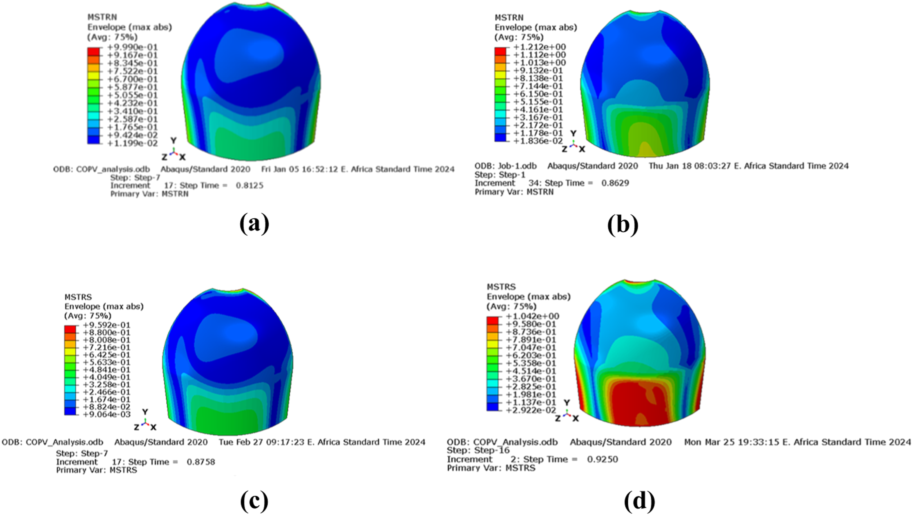
The Tsai-Hill failure indexes (TSAIH) are displayed in Figure 10(a) and (b), corresponding to step times of 0.685 and 0.86, respectively. In Figure 9(a), the maximum Tsai-Hill failure index consistently stays below one throughout the entire model, rendering the failure index insignificant for this particular load step. In contrast, Figure 10(b) reveals that the maximum Tsai-Hill failure index surpasses one (1) at the end of the model and in the large hoop area at the 0.86 step time. Consequently, this specific load step increment is considered indicative of burst pressure indexes, with the calculated burst pressure at this time being (0.86 * 30 MPa) = 25.8 MPa. Al/CFRPC failure index values for (TSAI-Hill) and (TSAI-Wu) failure criterions.
The Tsai-Wu failure indexes (TSAIW) are illustrated in Figure 10(c) and (d), corresponding to step times of 0.78 and 0.8125, respectively. In Figure 10(c), the maximum Tsai-Wu failure index consistently stays below one throughout the entire model, rendering the failure index insignificant for this particular load step. On the other hand, in Figure 10(d), the maximum Tsai-Wu failure index exceeds one (1) at the 0.8125 step time. Consequently, this particular load step increment is regarded as indicative of burst pressure indexes, with the calculated burst pressure at this time being (0.8125* 30 MPa) = 24.375 MPa. The counter plots depicting Hashin’s Fiber Compression Damage Criterion (HSNFCCRT) are showcased in Figure 11(a) and (b), corresponding to step times of 0.5829 and 0.785, respectively. The occurrence of burst pressure is identified when the Hashin’s damage (HSNFCCRT) value for fiber compression exceeds one (1). In Figure 11(b), it is notable that the COPV counter plot displays a maximum Hashin’s Fiber Compression Damage (HSNFCCRT) value surpassing one (1) at the 0.785 load step. Consequently, this particular increment in load step time is deemed indicative of the burst pressure value, with the calculated burst pressure now being (0.785 * 30 MPa) = 23.55 MPa. Figure 11(c) and (d) display the counter plots for Hashin’s Fiber Tension Damage Criterion (HSNFTCRT) at step times 0.7365 and 0.9125, respectively. Burst pressure is recognized when the HSNFTCRT value for fiber tension exceeds one (1). Notably, in Figure 11(d), the COPV counter plot exhibits a maximum HSNFTCRT value surpassing one (1) at the 0.9125 load step. Consequently, this specific increment in load step time is deemed indicative of the burst pressure value, with the calculated burst pressure at this time being (0.9125 * 30 MPa) = 27.375 MPa (Table 3). Al/CFRPC failure index values for (HSNFTCRT) and (HSNFCCRT) failure criterions. Summary of COPV burst pressure FEA result based on ASTM2585.
In Table 4, the 8th model of Al/CFRPC, comprising 13 layers, exhibited exceptional performance, achieving a peak burst pressure of 22.1 MPa at the PP [24.50, −24.50] s stacking sequence. Notably, despite not incorporating time steps, Finite Element Analysis of model-4 demonstrated sustained structural integrity for Al/CFRPC, with a failure index consistently below one. Further analysis of FEA results identified the sixth model as a standout performer, attaining an impressive maximum burst pressure of 25 MPa under specific conditions—namely, the PP [24.50, −24.50] s stacking sequence and utilizing only six layers for CFRPC. What distinguishes these models is that it’s capacity to achieve the highest burst pressure with a reduced number of layers, offering a distinct advantage in weight reduction while enhancing overall performance.
Effect of fiber orientation on burst pressure
The Finite Element Analysis (FEA) results, detailed in Table 4, reveal a significant trend regarding the impact of fiber orientation angles on burst pressure in Carbon Fiber Reinforced Polymer (CFRP) materials. This trend demonstrates that variations in fiber angle significantly affect burst pressure. A closer examination shows that as the winding angle approaches 24.50 degrees, there’s a notable improvement in burst pressure for both CFRP composites. This finding suggests that a specific fiber orientation angle, around 24.50 degrees, optimizes burst pressure performance in both materials. To illustrate this trend, the average pressure, calculated from all burst pressure values based on the chosen failure criteria, exhibits alternating patterns as the orientation angle changes. The accompanying Figure 12 visually represents these fluctuations, showcasing how burst pressure varies with fiber orientation angles. Overall, these findings highlight the intricate relationship between fiber orientation angles and burst pressure performance in composites. Understanding this relationship is crucial for optimizing the design and performance of composite structures, especially in applications where burst pressure is a critical factor. Variation of Average Burst pressure with increasing winding angle.
Effect of stacking sequence of layer
In the finite element analysis of models six to 11, a consistent orientation angle of PP [24.50, −24.50] s was applied for CFRPC. The primary focus of the study was to explore how varying the number of layers, while maintaining a uniform thickness, affected burst pressure. The summarized results in Table 4, reveal a clear relationship between the number of layers and the resulting burst pressure. Notably, case-6 stands out, showcasing the highest recorded burst pressure of 25 MPa with six number of layers. This significant finding is visually depicted in Figure 13. The inverse correlation between fiber orientation and burst pressure suggests that as the quantity of plies or layers of fibers in a composite material increases, the burst pressure decreases. This relationship arises because more plies often lead to increased complexity in the fiber arrangement and potential for misalignment or non-uniformity. As the fiber layers accumulate, the ability of the composite to distribute and withstand internal pressures effectively can diminish. Additionally, increased ply quantity may introduce greater internal stresses or contribute to manufacturing defects that reduce the material’s burst pressure tolerance. Therefore, while adding more plies might initially seem beneficial for strength, it can paradoxically reduce the burst pressure capacity due to those factors. Effect of an increasing number of layers on burst pressure.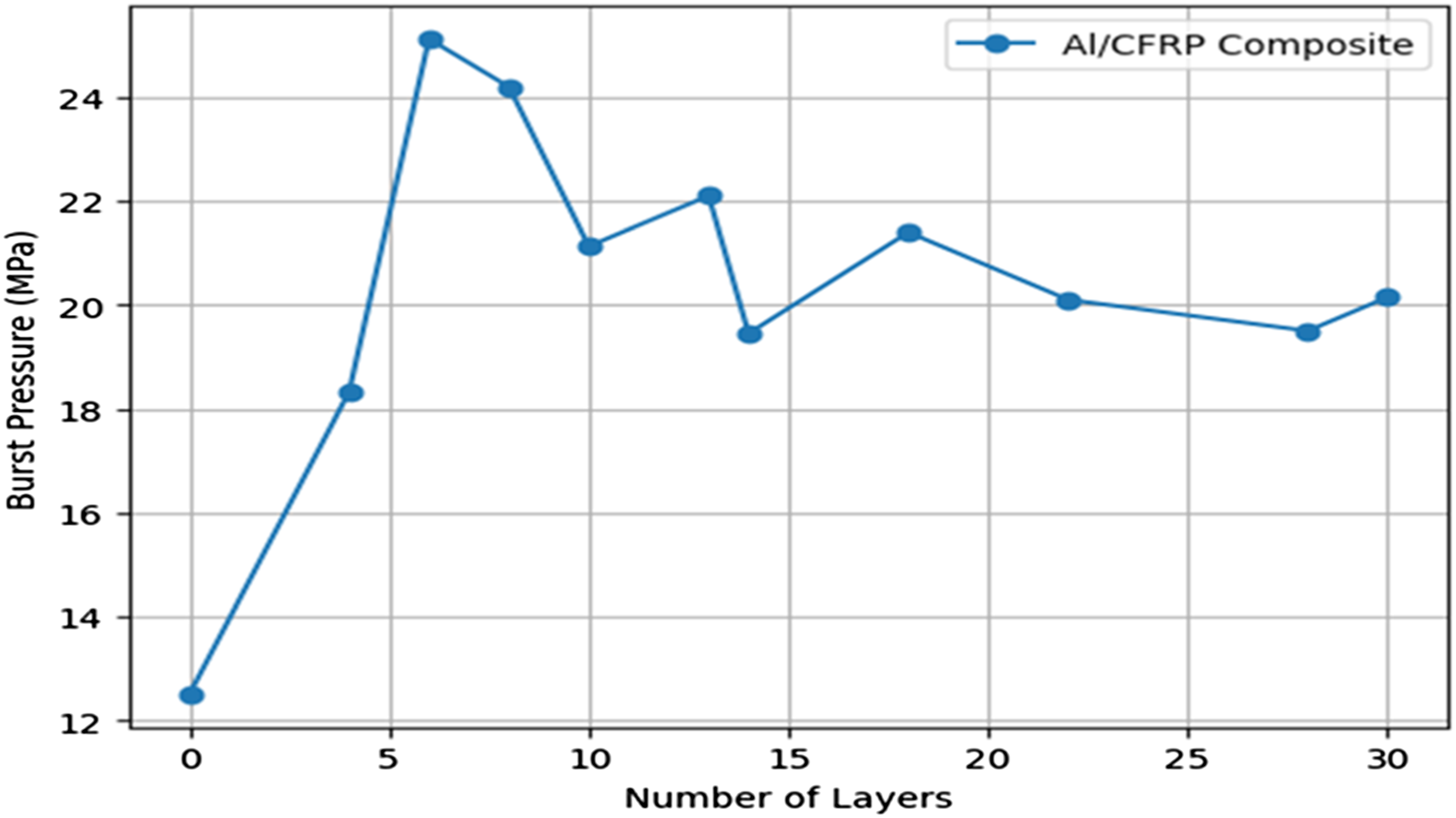
Fiber stress strain distribution in composite overwrapped pressure vessel
The analysis of stress and strain distribution in a composite overwrapped pressure vessel reveals significant stress and strain concentrations, particularly in the polar boss region, where the composite thickness and variations in winding angle have pronounced effects. The study across different models uncovers distinct patterns, with maximum in-plane principal stress and strain showing considerable variation as fiber orientation changes. By optimizing fiber angles, a stress-strain graph demonstrates a general upward trend, indicating that alterations in fiber orientation influence the overall stress and strain behavior. Peak strain levels are notably high when the fiber angle approaches θ ± 24.5°, highlighting the critical role of fiber orientation in determining stress and strain distribution within the vessel. This trend, illustrated in Figure 14, underscores how precise fiber alignment is crucial for optimizing the structural performance of composite pressure vessels. Graphical representation of Strain stress relationship for the Al-CFRPC.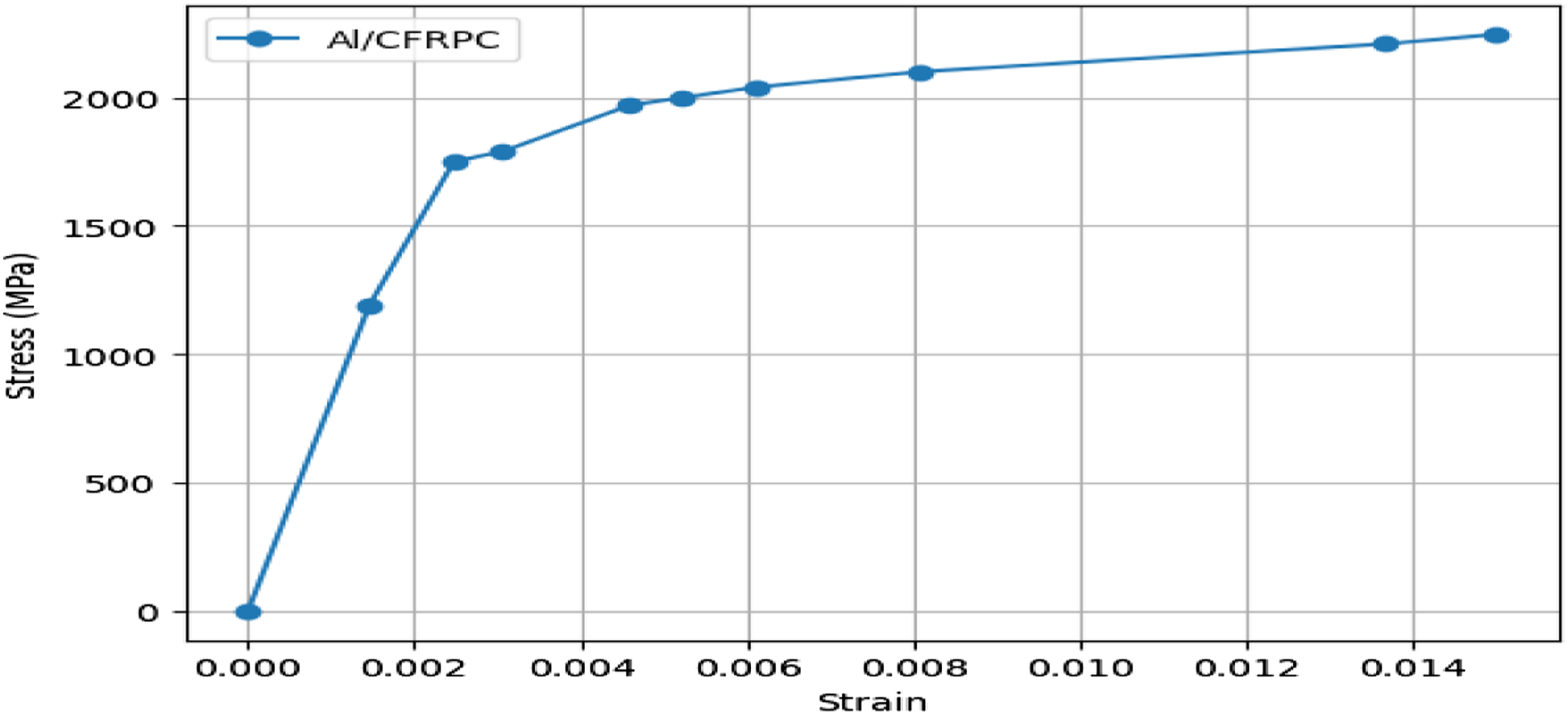
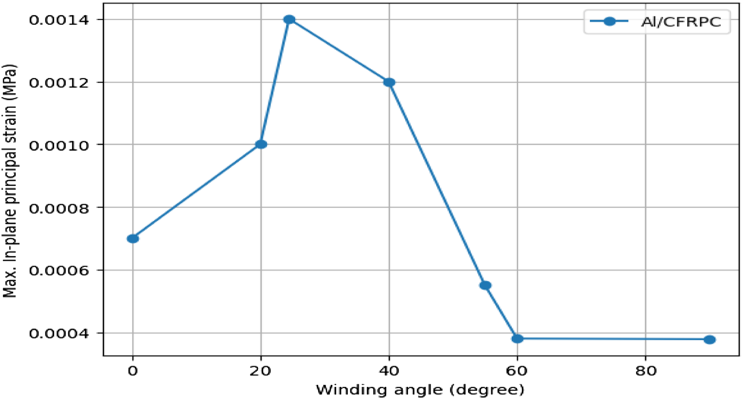
The intricate interplay among in-plane principal stress, strain, and winding angle significantly influences the distribution of stress-strain within the material, thereby shaping its mechanical behavior. Figures 15 and 16 vividly depict the fluctuations in maximum in-plane principal stress and maximum principal in-plane strain, respectively. Superior performance. Remarkably, the maximum in-plane stress and strain occur at peak values when the winding angle approaches θ ± 24.5°, underlining the critical role of fiber orientation in determining mechanical properties of the composites. Verification of maximum principal stress with increasing winding angle. Verification of maximum principal strain with increasing winding angle.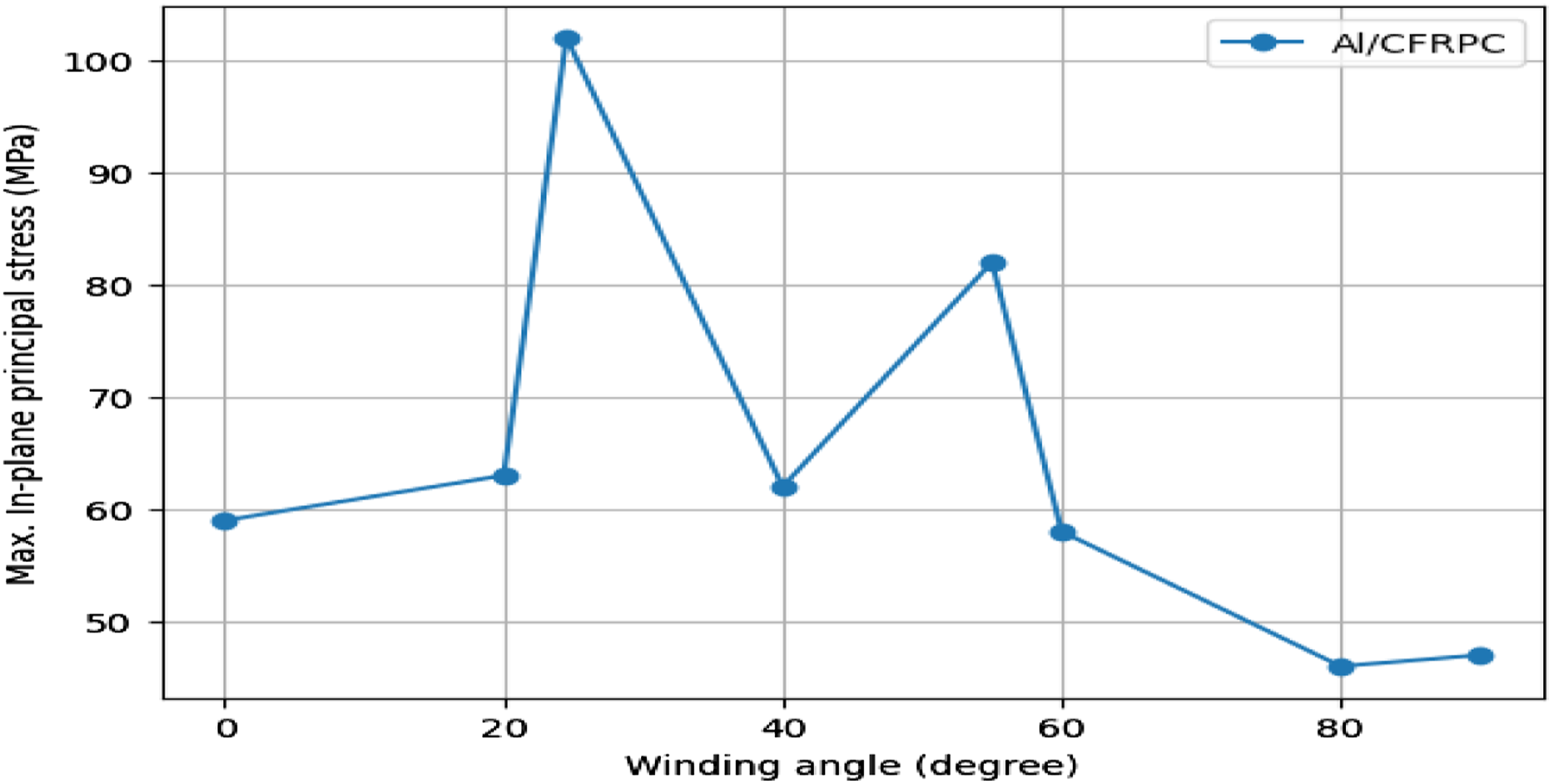
Composite shear strength analysis
Figure 17 of the graph illustrates that the shear strength of CFRP composites decreases as the winding angle increases. The decline in performance observed as the winding angle increases from 0 to 90° can be explained by fundamental principles of composite material behavior and stress distribution. At angles close to 0°, fibers are oriented along the primary load direction, which enhances their ability to bear the applied stress and optimizes the composite’s strength and efficiency. As the winding angle increases, fibers become more oriented perpendicular to the load, reducing their effectiveness in supporting the load. This misalignment leads to less efficient stress transfer, higher localized stress, and a decrease in structural integrity. When the angle reaches 90°, the fibers are nearly parallel to the applied stress, worsening these issues and causing a notable drop in performance. This pattern, illustrated in the graph, highlights the importance of carefully selecting fiber orientation to ensure that composite materials retain their strength and reliability in practical applications. Predicted shear strength of Al-CFRPC using line plots.
Axial and radial deformation of COPV
When a Composite Overwrapped Pressure Vessel (COPV) is subjected to internal pressure, it can deform in two primary ways: axially and radially. Positive axial deformation indicates lengthening of the vessel, while negative deformation signifies shortening. Excessive lengthening can place undue stress on the end fittings and liner material, potentially leading to failure or buckling. Radial deformation is characterized by outward expansion (positive) or inward contraction (negative). Excessive radial expansion can stress the composite layers beyond their limits, leading to potential delamination (separation between layers) and difficulties in fitting the COPV into its intended application. Figure 18 illustrates the relationship between internal pressure and deformation for Al-CFRP composite materials, with (a) showing Internal Pressure versus Axial Deformation and (b) showing Internal Pressure versus Radial Deformation. The graph indicates that Al/CFRP composites experience relatively minimal axial and radial deformation under the same applied pressure. This behavior is attributed to Al/CFRP’s high Young’s modulus (E) and ultimate tensile strength, which confer enhanced stiffness and strength properties, making it an excellent choice for applications where rigidity and dimensional stability are critical. Axial (a) and Radial (b) Deformation under internal pressure.
Ensuring precise representation of the physical system and meticulous mesh refinement are crucial for accurate results, while correctly defining boundary conditions and mesh size is vital for capturing realistic system behavior. Al/CFRPC boasts superior stiffness and strength owing to its composition, thereby offering heightened resistance against bending and bulging when subjected to pressure. This inherent rigidity renders it particularly suitable for applications where structural integrity and shape retention are paramount. Understanding these material characteristics is essential for selecting the most appropriate material for specific engineering applications. The analytical assessment of composite shear strength, particularly employing the Maximum strain, Tsai-Wu and Tsai-Hill criteria, unveiled the most robust predicted shear strength among the array of failure criteria scrutinized. The Tsai–Wu failure theory is noted for its reliability in analyzing the stress–strain characteristics of composite structures, particularly in assessing burst pressure. 23 Designs that rely on the tensile strength of fibers to withstand gas-induced loads are shown to be more effective than other approaches. 52 Burst pressure, like other measurable parameters, is mainly influenced by vessel material and the dynamics or statics of the stored content. As the fiber volume ratio increases, fiber strength also rises, leading to higher burst pressure capacities. Optimal fiber orientation further improves burst pressure resilience. When designing Composite Overwrapped Pressure Vessels (COPVs), it’s essential to consider three key factors: winding angle, ply thickness, and stacking sequence. Proper optimization of these factors is crucial for creating a durable COPV that can mitigate optimum burst pressure concerns. This underscores an important lesson and suggests an area for further investigation by future researchers. A comprehensive analysis of the burst pressure resulting in failure was carried out, considering various scenarios involving different stacking orders, fiber orientations, and ply thicknesses to evaluate the COPV’s response to internal pressure.
Conclusions
Scholarly research highlights the widespread adoption of Composite Overwrapped Pressure Vessels (COPVs) within the aviation sector for crafting solid rocket motor casings, Automotive, and propellant tanks. Moreover, industries involved in steam production and utilization leverage COPV technology to engineer lightweight, high-pressure liquid storage tanks, offering flexibility in selecting inner lining materials. Additionally, COPVs serve as an efficient solution for storing highly compressed hydrogen, crucial for powering environmentally friendly vehicles. The present research highlights the critical significance of Composite Overwrapped Pressure Vessels (COPVs) in improving the efficiency and reliability of pressure vessels. To enhance the sophisticated development and manufacturing of COPVs, greater attention should be directed towards refining netting design and analyzing factors such as fiber winding angles, ply thickness, manufacturing methodologies, and innovative materials for fiber or lamina bonding. This comprehensive approach is essential for achieving optimal structural integrity in COPVs. The study aimed to identify the optimal combination of layer quantity and orientation angle to optimize burst pressure in COPVs, offering essential insights into their performance dynamics. The findings reveal that the 6th model, featuring six (6) layers wound with angles [24.50, −24.50] PP, demonstrates exceptional burst pressure performance of 25 MPa. Importantly, the analysis unveils a dynamic correlation between burst pressure and varying fiber angle orientations, underlining the importance of precise configuration in achieving peak performance.
Based on the study’s model, conclusions such as [24.50, −24.50] orientation were made. If the dimensions of the composite overwrapped pressure vessel are different, the optimal orientation for this design will not function. The extremely targeted orientation optimization for the unique vessel geometry and stress distribution. Different stress distributions are produced by COPVs with varying diameters and lengths. An extended length may result in a rise in axial stress, but a greater diameter raises the hoop stress. In a vessel with variable dimensions, the highest resistance to these stresses might not come from the ideal fiber orientation for one set of dimensions. The stress distribution is also influenced by the size and form of the vessel’s end domes. It is possible that a fiber orientation that was designed with a particular end dome geometry won’t work if the dome’s size or form changes. Using material as effectively as possible to offset the stresses the vessel is subjected to is the goal of fiber orientation optimization. The stress pattern will alter if the dimensions vary, and the previously optimal orientation could result in wasteful material use either too much material in some places, increasing weight, or too little material in other regions, reducing strength. Stress patterns inside the vessel have an impact on COPV failure modes such fatigue life and burst pressure. A fiber orientation that optimizes these factors for one set of dimensions may not achieve the same results for another set, possibly leading to premature failure or reduced safety margins. In summary, an optimized fiber orientation for one COPV design will not necessarily be optimal for other designs with different dimensions. Each design requires its own tailored optimization to ensure maximum performance, safety, and material efficiency.
Furthermore, the examination of failure criteria emphasizes the robustness of Hashin’s damage failure criterion in identifying critical failure modes, particularly in the hoop area of the cylindrical section Al/CFRPC. Specifically, burst pressure values derived from the Tsai-Hill and Tsai-Wu failure criterion consistently exhibited a more conservative trend, with lower values compared to those obtained from other failure criteria. Moreover, the analytical assessment of composite shear strength, particularly employing the Maximum strain, Maximum stress and Tsai-Wu criteria, unveiled the most robust predicted shear strength among the array of failure criteria scrutinized. Overall, the research findings offer valuable guidance for optimizing COPV design parameters, ultimately enhancing pressure vessel efficiency and reliability in various industrial applications. This comprehensive understanding of COPV behavior significantly advances pressure vessel technology, ensuring the development of safer and more robust systems for critical industries such as Aerospace and Automotive industries.
Footnotes
Acknowledgements
I am deeply grateful to Dr Yohannes Regassa for his generous support, guidance, and engaging in insightful discussions.
Declaration of conflicting interests
The author(s) declared no potential conflicts of interest with respect to the research, authorship, and/or publication of this article.
Funding
The author(s) received no financial support for the research, authorship, and/or publication of this article.
Data availability statement
All data analyzed during this study are included in this research article.