
Abstract
Several CFRP laminates with various layups, possessing two distinctive forms of transverse reinforcement either UD 90° or fabric 0°/90°, were tested in both static and fatigue tests. All examined layups were considered to be used in the wingbox design of the multipurpose turboprop aircraft. In-situ microscopic observations were carried out during the tests. Static tensile tests allowed to find the strength of the laminas, stress, and strains at which cracks started to propagate, crack density during the test. The microscopic observations allowed to establish cracks’ growth paths. The first crack in laminates having fabric 0°/90° laminas usually was observed for higher stress and strain than in laminates with UD 90° laminas. Also, the later ones showed a tendency to significantly delaminate along the interface between UD 90° and UD 45° laminas. The fatigue test was carried out in order to find how to distinguish damage growth in both families of laminates that affects their fatigue life. As an outcome, S-N lines were determined. During the test the microscopic observations were made, which allowed to show crack and delamination growth during successive load cycles. The microscopic observations showed that cyclic loading leads to the fast growth of delaminations at the interface of fabric 0°/90°ply or UD 90° laminas.
Introduction
Automated fiber placement (AFP) and automated tape laying (ATL)1–4 processes have become potent methods of fabrication elements of aircraft including safety-critical components. The most important attributes of APF and ATL methods are a high level of automation, high production rate (particularly in case of flat components), low recurring costs, repeatability and high quality of manufactured composites. 5 Usually, AFP lays fiber down in the form of prepregged unidirectional (UD) tape.
Aerospace structures make use of many favorable properties of carbon fiber reinforced polymers (CFRP) such as lightweight, high specific strength, and good corrosion resistance.6–9 However, the application of CFRP opens up yet another great design opportunity-tailoring of mechanical properties to meet the needs of specific component. 10 Anisotropic nature of carbon fibers allows making composite components strong and stiff in direction of anticipated loads, while others less stressed or even unstressed could be significantly weaker. The component, which takes advantage of this CFRPs property, will show optimal design and possess low weight and high strength.
However, some strength in a direction perpendicular to the primary load path is required by certifying agencies such as FAA 11 or EASA. 12 In order to fulfill this need, composite panels have fibers oriented not only in 0° direction (along load direction), but also ±45°and 90°.13,14
The presented data are part of the study resulting in the design of the light multirole aircraft ILX-34. The study shows part of the effort made to design a composite central wingbox fabricated using various composite technologies e.g. thermoforming of thermoplastic materials or AFP. The main purpose of the presented research was to find the form of the reinforcement in the transverse direction (i.e. 90), which would provide high static strength, high fatigue properties, and low crack/delamination growth. Two forms of the transverse reinforcement were tested—layers of UD tapes in 90° direction and layers of plain-weave fabric with warp along 0° and fill along 90° direction. Particularly, incorporation of fabric plies into laminate seems to be promising due to an increase of impact resistance15,16 of such composite, which is a major concern in the certification of composite elements for general aviation and commercial aircraft. 17 The 90° UD layers are known to crack at much lower stress/strain levels than plies oriented at 0°. Although it has a negligible effect on strength of the multidirectional laminate, 18 it can ease moisture absorption19,20 and allow penetration of fluids (jet fuel, hydraulic oil, cleaner, etc.). Cracks formed in the transverse layer may make crack/delamination 21 propagation easier what could be deteriorating fatigue performance. Despite lower stiffness and strength of the fabric plies, they are believed to be more resistant to the formation of cracks and help to inhibit damage growth.18,22,23 Several reports cover various methods of damage growth evaluation in CFRP laminates, including microscopic observations 24 and X-ray imaging.25,26 Yudhanto et al. published work, 26 which presents damage growth during the static tensile test. In unstitched multidirectional composite formation and growth of transverse cracks at a strain of around ɛ = 0.5% followed by the formation of oblique cracks (in ±45° plies) and delaminations. Hosoi et al. 25 investigated fatigue-induced damage growth in quasi-isotropic laminate. Authors reported following sequence of damage growth—(i) transverse crack formation in the 90° plies, (ii) delaminations growth along 45°/90° or 90°/90° interfaces, (iii) cracks formed in the 90° plies propagate into ±45° plies, and (iv) specimen failure due to the 0° plies brake. A similar study was held by Nishikawa et al., 24 who investigated fatigue-induced damage growth in various plain-woven CFRPs using microscope observation. At stress level of 75% tensile strength, after as few as 106 cycles, transverse cracks in weft and local delaminations along warp/weft interface were observed.
The presented results allowed us to understand behavior and select layup of the wingbox skin.
Experiment and materials
Materials
Material identification and lay-ups.
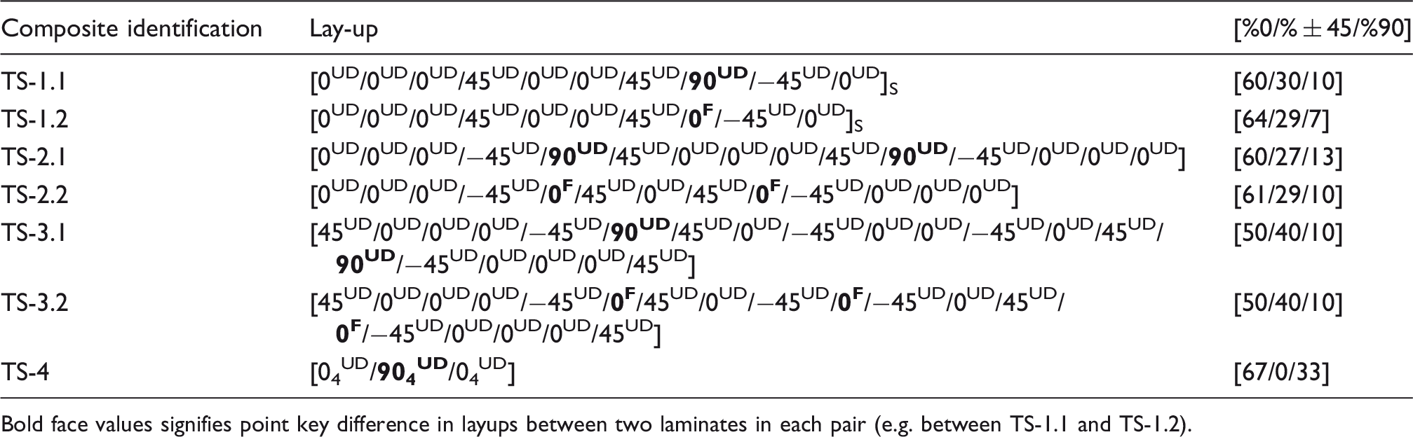
Bold face values signifies point key difference in layups between two laminates in each pair (e.g. between TS-1.1 and TS-1.2).
Mechanical properties of laminas used to manufacture tested laminates.
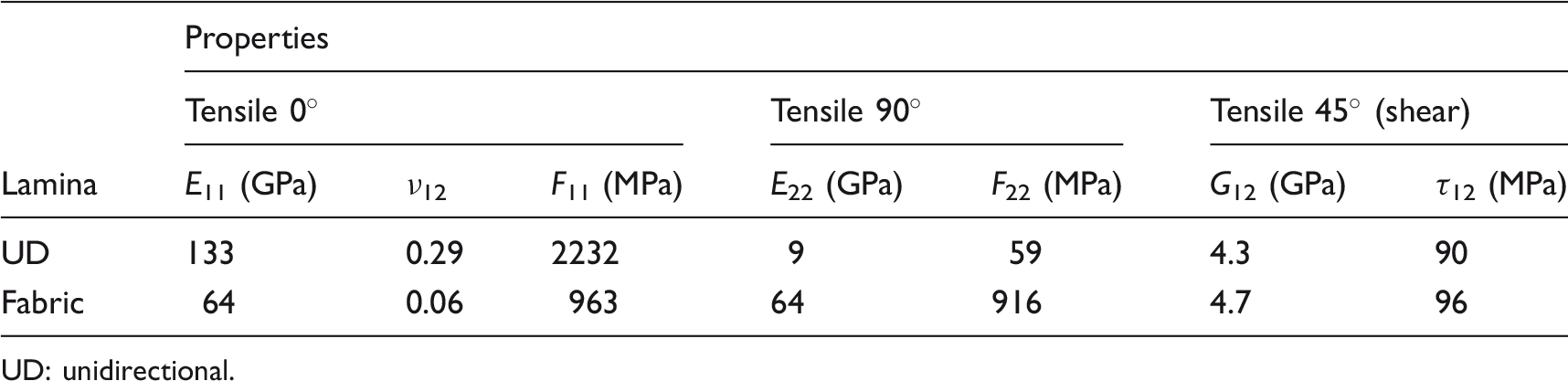
UD: unidirectional.
Experiment
Microstructure examination
Prior to the test, one side surface of each coupon was ground and polished, starting from emery paper with a gradation from #320 to #2500, then 3 µm and 1 µm diamond suspensions were used. The final step was polishing with a water suspension of 0.05 µm alumina. During the test, polished surface of each coupon was observed with a digital microscope (Keyence VHX-6000); 100× magnification was used, it allows monitoring relatively large 2.8 × 3.5 mm
2
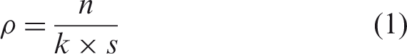
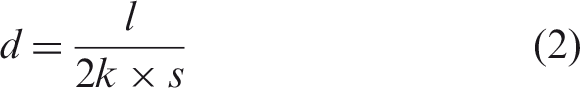
area of the specimen, find crack and delamination nucleation, and propagation. Higher magnification was also tested; however, due to the vibration of the testing machine, images had low quality. The microscopical observations allowed to quantify ongoing degradation of the laminates—transverse crack density or level of delamination. These factors were calculated using the following formulas
Tensile test
The tensile test was conducted in accordance with ASTM D3039 standard. Hydraulic universal testing machine MTS 322 equipped with hydraulic grips was used (Figure 1). Tabbed coupons with a length of 256 mm and a width of 12.7 mm were used. The ASTM standard recommends the use of coupons with a width of 25.4 mm for multidirectional laminates; however, narrower coupons were used due to a large portion of strong 0° UD layers and anticipated high strength. The strain of each coupon was measured with an extensometer with a gauge of 50 mm; additionally, onto some coupons 6.35 mm strain gauges were bonded.
Testing setup (tensile test).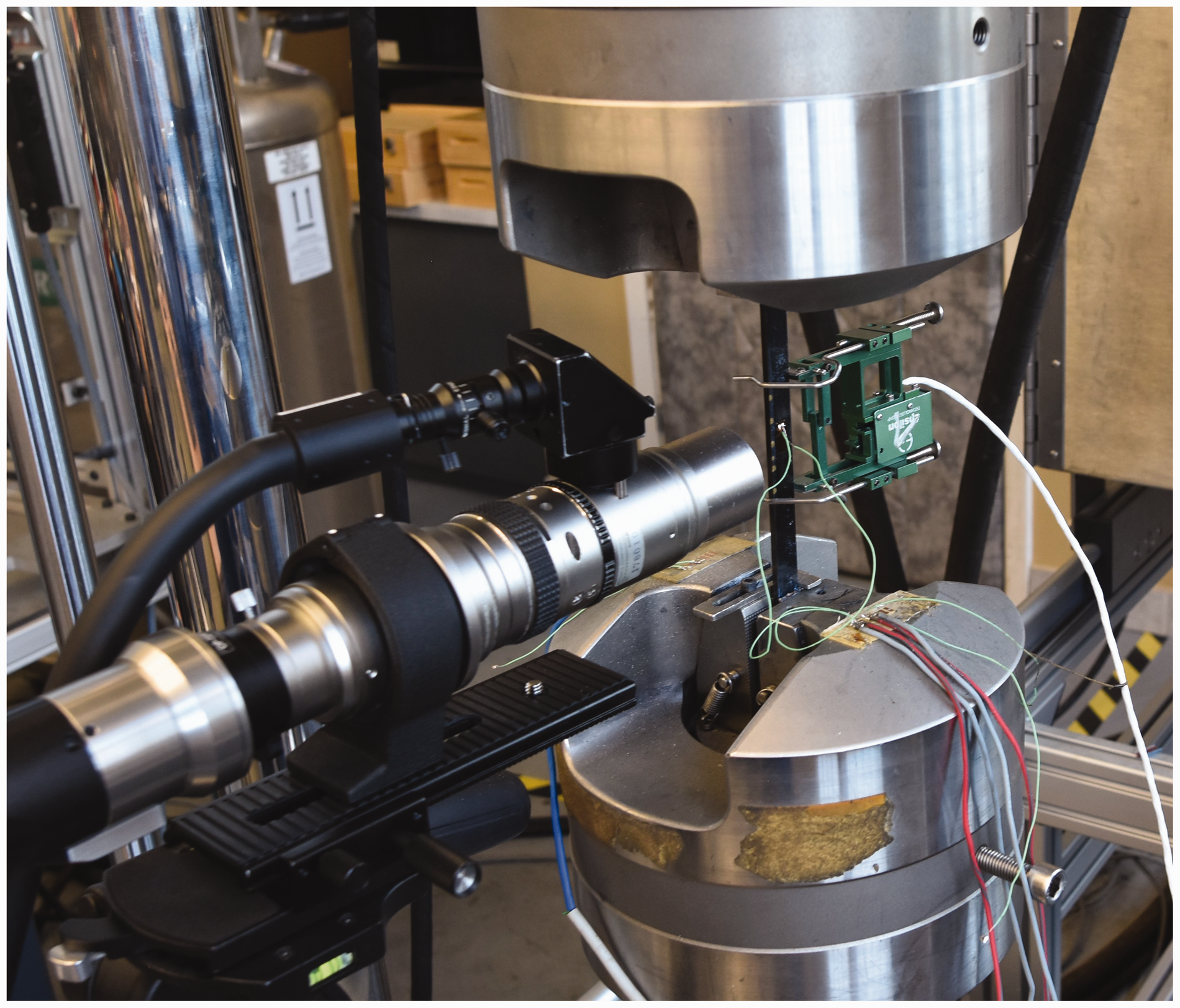
Six coupons of each layup were tested. Four of them were tested by loading with a strain rate of 1.5 × 10⁻² s−1 to failure. During the test, video showing microstructural changes was recorded with the microscope. In order to get more statistically relevant information, two other coupons were tested by stepped tensile—after reaching predefined load level, the test was held for about 2 min, which allowed to take four images, covering about 10 mm of specimen’s length. Then, the coupon was loaded to the next step; the procedure was repeated until final failure.
Fatigue test
For three layups (marked in Table 1), the tensile-tensile fatigue test was carried with stress ratio R = 0.1 and frequency of 3 Hz. The test was carried according to the general recommendations of the ASTM D3479 standard. The same testing setup and coupon geometry were used in both fatigue and tensile tests. The fatigue test was carried until failure of the coupon or reaching 75,000 cycles. It is well known that right gripping is essential in acquiring valid data. Too high gripping pressure may result in stress concentration in the gripping region of specimen and premature failure, on the other hand, too low pressure will cause specimen slipping in grips. To avoid this problem, the minimum pressure needed for a solid grip without slipping for each load level was determined.
Results and discussion
Microstructure
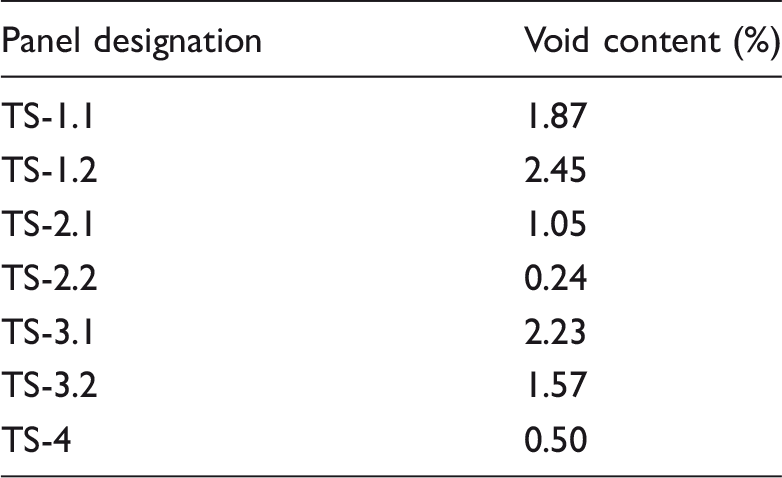
After manufacturing tested panels were examined, using NDT quality check and all of them met the requirement described in Section “Materials.” The NDT examination gives limited information about the inner structure of the laminate thus additional microscopic examination was carried out. Images presented in Figure 2(a) to (g) show cross-sections of the investigated laminates. In general, all tested laminates possess good quality—very small porosity, lack of delaminations, lack of dry fibers, etc. Void content measured by image analysis of laminates’ cross-section is summarized in Table 3. All panels had a porosity level below 2.5%, which well corresponds with the NDT results. Images allow to clearly distinguish UD and fabric plies oriented in 0°, 45°, 90° directions. Several pores with a size of a few hundred micrometers are observed at the interface between two adjacent UD plies (Figure 2(a), (c), and (e)). Such distribution of defects may be caused by a single debulking process done after the complete laminate was prepared, as a result, the air trapped between two plies can not be removed and form voids. Images of layups containing plain weave fabric layers reveal wavy 0° tows of the fabric plies and resin-reach pockets. In the case of layup consisting of both UD and fabric plies low porosity is observed, there were very few pores at the interfaces of fabric plies (Figure 2(b), (d), and (f)). Such a good quality was obtained by the frequent debulking process, taking place after each fabric ply was lain.
The images of microstructure of laminates (a) TS-1.1, (b) TS-1.2, (c) TS-2.1, (d) TS-2.2, (e) TS-3.1, (f) TS-3.2, and (g) TS-4/. Voids content in tested panels.
Tensile test
The results of tensile tests are shown in Table 4. All of the tested coupons showed linear behavior without a notable change of strain-stress line with damage accumulation. Only small “humps” on the line appeared where some 0° oriented tows broke, the appearance of those humps took place together with loud noises. The Young’s modulus values and strength of the laminates are closely correlated with the percentage of 0° fibers.
27
Replacement of two 90° UD plies with two 0° plain weave plies (TS-1.1 and TS-1.2) led to an increase of 0° fibers in laminate, thus increase in both modulus (from 84 to 89 GPa) and strength (from 1365 to 1525 MPa). Microscopic observations revealed the moment of the first crack appearance (Figure 3), which is always in 90°UD ply or 90° tows in fabric ply. The first crack showed up at lower stress in TS-1.1 laminate. Figure 3 shows the details of failure propagation in TS-1.1 and TS-1.2 laminates. In the former case, the first crack shows in 90° UD ply, at a stress level of about 55% of strength. Very often crack nucleation at ±45°/90° interface flaws (marked with “A”) was observed. Along with increasing stress, more transverse cracks were formed. The crack tip located at the ±45°/90° interface was a starting point of growing delamination (“B”). At high-stress levels reaching as much as 90% of coupon’s strength, complete delamination of ±45° and 90° plies was observed, also, delamination and cracking of some outer 0° fibers was recorded (“C”). Very little drop of force during the tensile test suggest that not all plies broke but just some tows located at the edge (inside the studied area). The damage evolution in TS-1.2 laminate is less dramatic at around 65% of strength the first cracks in 90° PW tows appeared, increasing load led to increasing of transverse crack density but very little delaminations were observed. Figures 4(a) and 5(a) show a comparison of crack density and fraction of delaminations. It is clearly seen that both parameters are much lower for laminate containing plain weave reinforcement.
Damage evolution of TS-1.1 and TS-1.2 coupons during the tensile test. The number represents stress level normalized by laminate strength. Transverse crack density in (a) TS-1.1 and TS-1.2, (b) TS-2.1 and TS-2.2, (c) TS-3.1 and TS-3.2, and (d) TS-4 laminates. The fraction of delaminations along ±45°/90° interfaces in (a) TS-1.1 and TS-1.2, (b) TS-2.1 and TS-2.2, (c) TS-3.1 and TS-3.2, and (d) TS-4 laminates. Results of tensile tests.
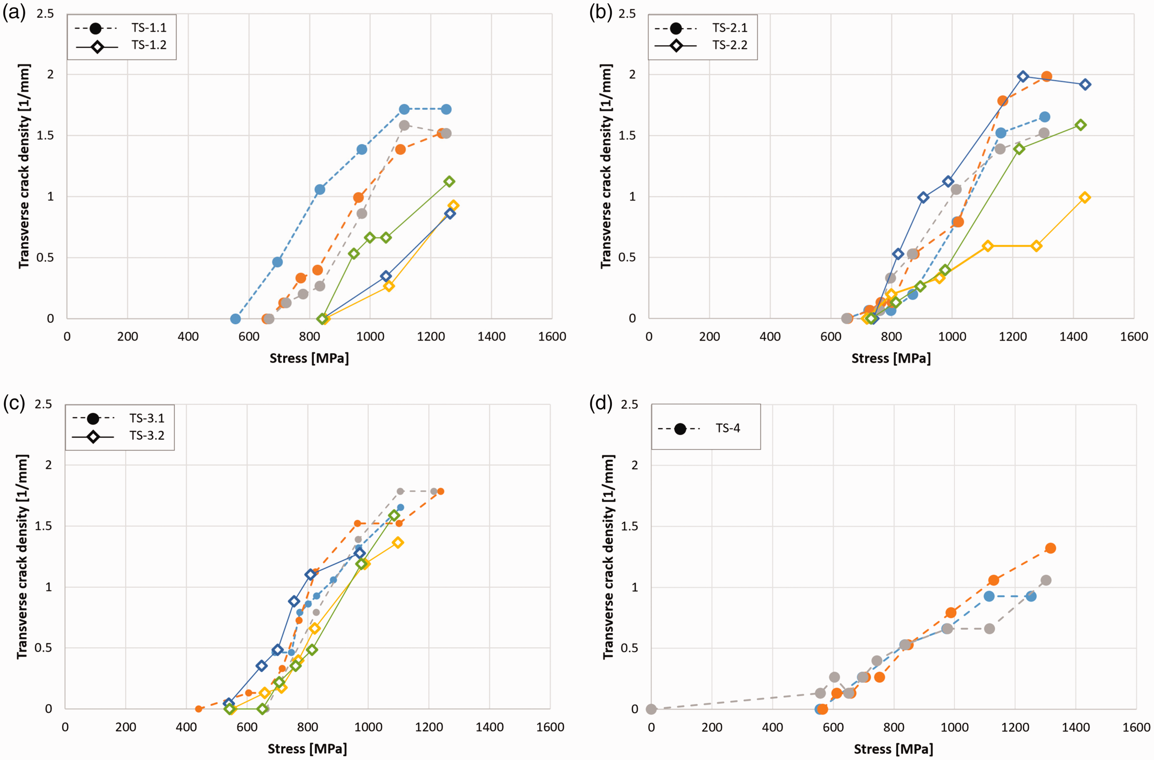

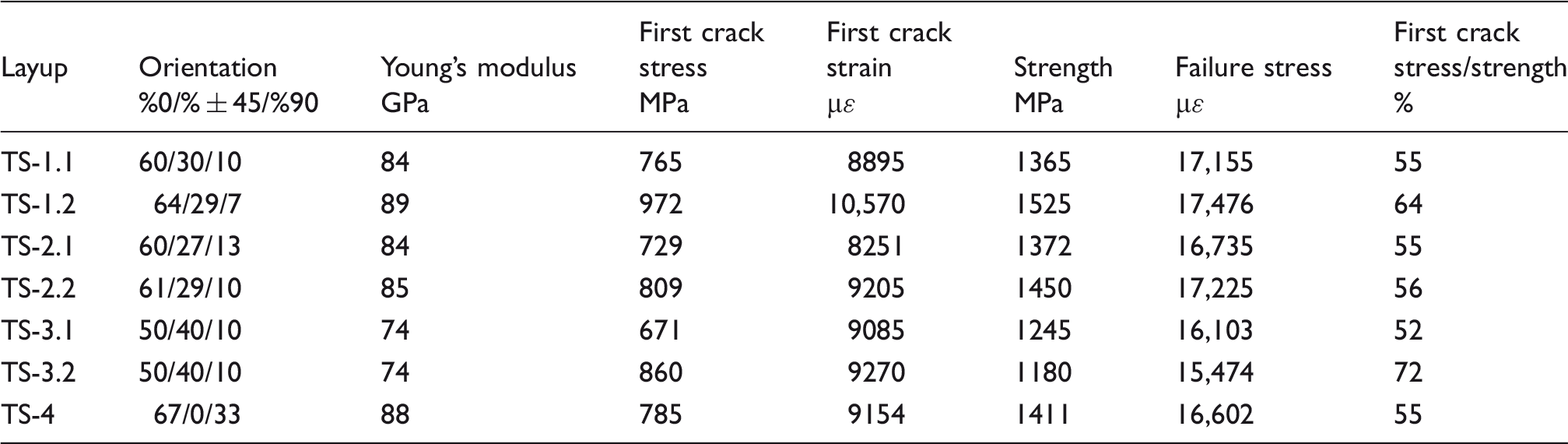
The second pair of laminates (TS-2.1 and TS-2.2) showed a similar portion of fibers in all orientations, however, the strength of laminates varies—TS-2.2 is stronger by 6% than TS-2.1. Also, the first crack showed up at higher stress. However, Figure 4(b) shows that the transverse crack density evolution of both laminates is not as distinctive as in the case of TS-1.1 and TS-1.2 laminates. There is a significant variation of crack density between TS-2.2 coupons—two coupons showed similar crack density evolution to TS-2.1 coupons and one showed lower density. Fabric reinforced laminates showed lower delamination density (Figure 5(b)). The third pair (TS-3.1 and TS-3.2) showed damage accumulation similar to the process previously described. In this case, despite the same fraction of fibers in each direction strength of the 90° UD reinforced laminate is higher than the fabric-reinforced laminate. It may be explained by the fact that fibers in the fabric are undulated and interact with transverse tows 28 what reduces load-carrying capacities of those fibers.
Due to the large fraction of 0° UD plies model laminate TS-4 showed high modulus and high strength. Despite the presence of undesired 0°/90° interfaces 10 both transverse crack (Figure 4(d)) and delamination (Figure 5(d)) densities grew slower than in other 90° UD reinforced laminates.
Tensile tests showed that the application of fabric to provide transverse strength of the laminate is highly promising—such laminates show high strength and have good damage tolerance—first transverse crack tended to appear at higher stress, the density of transverse cracks is generally lower than in UD reinforced laminates. Also, fewer and shorter delaminations were observed in the vicinity of fabric layers, thus there was less likely that laminates containing fabric plies would split into individual layers before failure. Such performance under load could highly beneficial in aerospace design were such events as fuel escape through leaky tank could be safety-critical.
Fatigue test
The fabric-reinforced laminates have a degree of damage tolerance (late appearance of first crack, fewer transverse cracks, and delaminations) which is of crucial importance in fatigue performance.29–31 The fatigue tests on three selected laminates—TS-1.1, TS-3.1, and TS-3.2—were performed. The S-N plots are presented in Figure 6, which show dependence between a number of cycles to failure and (a) absolute maximum stress in a cycle or (b) stress normalized by each laminate’s strength. Figure 6(a) shows results for three tested laminates along with fitting lines, fatigue performance may be sorted in following order TS-1.1, TS-3.1, and TS-3.2, which is not surprising since it corresponds with the strength of each laminate. Figure 6(b) shows laminates’ fatigue performance in reference to their strength. The plot shows that results of UD-reinforced overlap, also limit of 75,000 cycles were reached for both laminates at a stress level of 70% of strength. The plot shows inferior fatigue performance of fabric-reinforced laminate—data point lies below those of TS-1.1 and TS-3.1, also fatigue limit was reached for just 50% of laminates strength.
S-N diagrams showing a number of cycles to failure as a function of (a) maximum applied stress and (b) maximum stress normalized to laminate strength.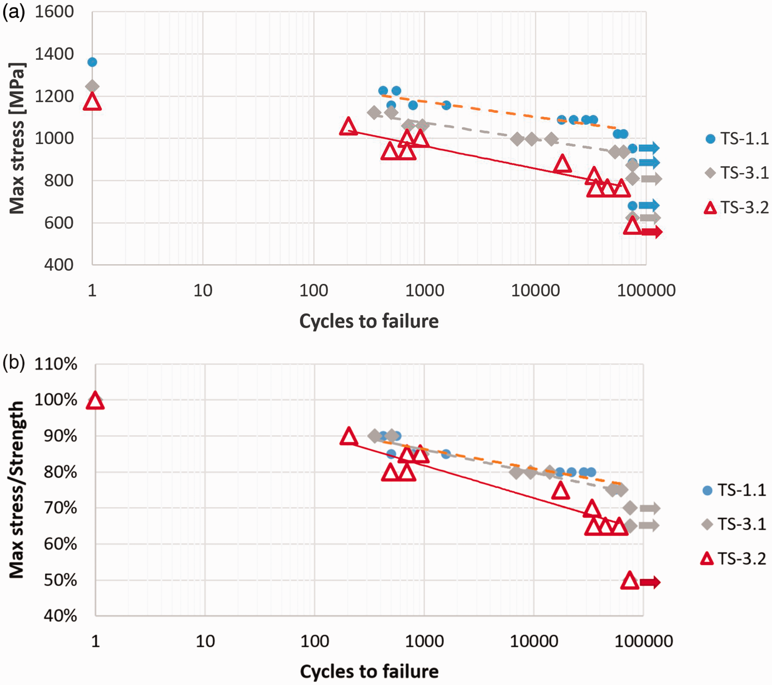
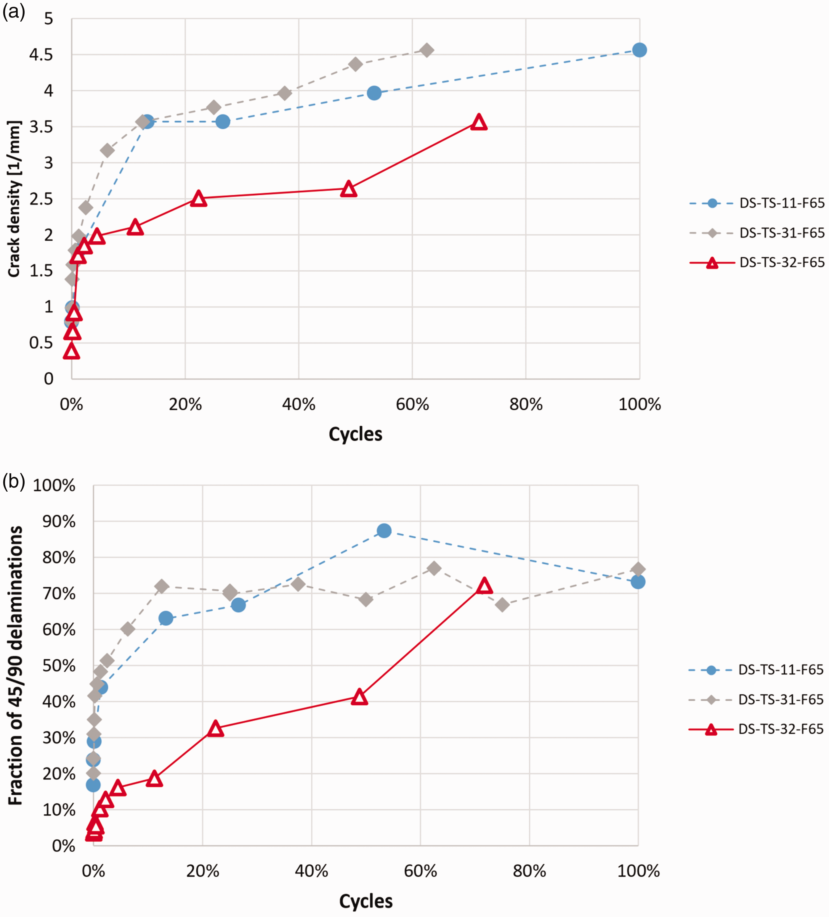
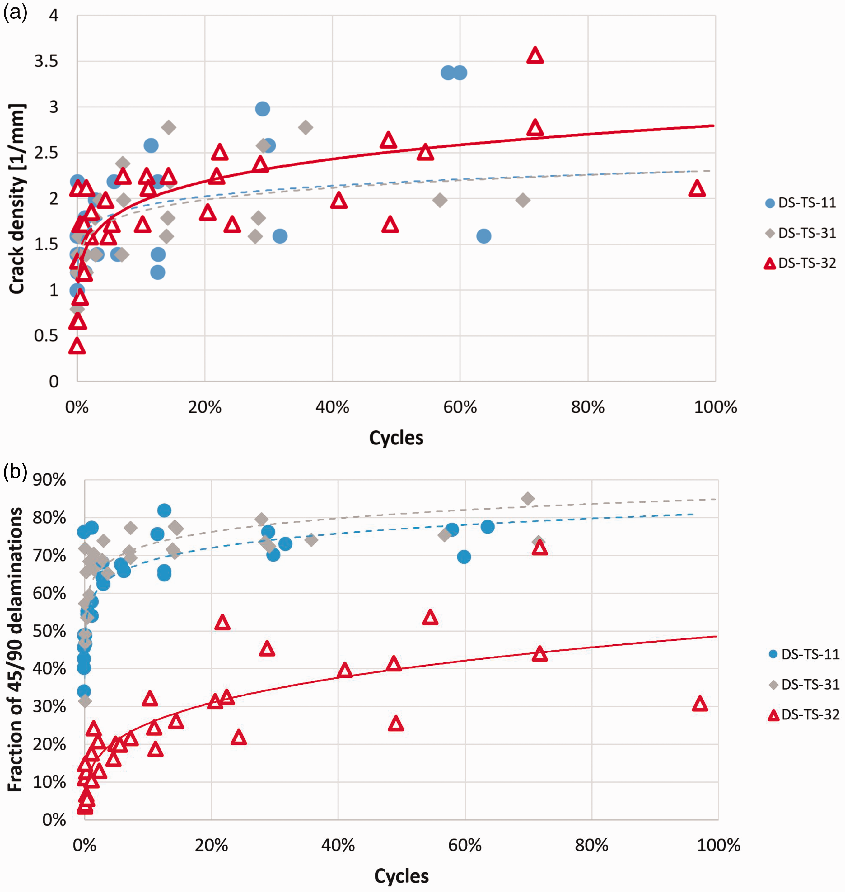
The evolution of damages in cyclically loaded laminates TS-3.1 and TS-3.2 are presented in Figure 7. Both shown coupons were loaded to 65% of their strength. After first loading damages correspond to those visible in the tensile test, cracks in 90 plies showed up in TS-3.1 coupon (labeled by “E”), while TS-3.2 laminate remains undamaged (the first crack threshold is about 72% of strength). After the 1000th cycle degradation process proceeded in both laminates in TS-3.1 new cracks were formed both in 90° (“F”) and 45° (“G”) plies. Nucleation and propagation of transverse cracks in 45° seem to be typical for fatigue loads since it was not observed during monotonic loading. After 1000 cycles growth of delaminations between 90° and 45° plies (“H”) was seen. After 10,000 cycles, no new cracks in 90 plies were observed, however, a high density of cracks within 45° plies (“I”) was revealed. Also, major delaminations (“J”) were found – in observed part of the coupon total disbanding of 45° and 90° plies happened. After reaching the fatigue limit of 75,000 cycles, the coupon was split into 3–4 parts (“K”) with no or little connection between them. Figure 8 presents how crack and delamination densities changed during fatigue loading at 65% of strength, it confirms previous remarks that crack density and delaminations growth very vast during the early stage of fatigue process (up to ∼10%), while further loading does not lead to significant degradation of composite’s structure. The final failure is then determined by the dramatic cracking of load-carrying 0° fibers. Figure 9 shows the evolution of both crack and delamination density during the fatigue process extended to all stress levels. Large data-scatter is obvious; however, the general trend in the early growth of transverse cracks and delamination is seen.
Damage progress during fatigue in TS-3.1 and TS-3.2 laminates. The maximum fatigue cycle is 65% of laminate’s strength. (a) Transverse crack density during the fatigue process at 65% of laminate’s strength and (b) fraction of 45/90 delaminations during the fatigue process at 65% of laminate’s strength. (a) Generalized changes of crack density for all applied stress levels and (b) generalized delamination growth.
Damage evolution of TS-3.2 laminate undergoing a load level of 65% of strength is different from one described previously. After 1000th cycle, cracks in 90 tows of fabric were revealed (“L”), which then propagated into 45 layers (“M”). After 10,000 cycles limited delaminations at fabric/±45 layers were found (“N”), but some major discontinuities between other layers (“O”) were seen. At 44,424 cycles (just 274 cycles to final failure), specimen was split into several layers. Figure 8 shows that at 65% of strength TS-3.2 coupon was more resistant to formation transverse cracks and delaminations around fabric layers. Interestingly, there is no rapid growth of delaminations at the beginning of fatigue, which was observed in TS-1.1 and TS-3.2 laminates.
Figure 9 shows that for other (higher) loads crack density in TS-3.2 during undergoing fatigue is similar to that one in two other tested laminates. The fraction of fabric/45° layer delaminations is significantly smaller than a fraction of 90°/45° delamination in UD-reinforced laminates.
Results of fatigue tests are in clear opposition to predictions based on the quasi-static tensile test. Presented results show that fabric layer does not degrade faster than 90° UD plies, in fact, crack density within 90° tows of fabric is similar to 90° UD, but the growth of delamination at the surface of fabric layer is significantly slower. Nevertheless, images of late-stage TS-3.2 coupons shows severely damaged specimen split into several bands. The poor fatigue performance of fabric reinforced laminate could be explained by the change of stress distribution within the laminate—fabric layer do have lower stiffness, even 0° tows in the fabric should be considered as having lower stiffness due to their undulation. 16 There is a rule of thumb that “stiffness attracts stress,” thus stiff 0° fibers in 0° UD plies carry a higher load than 0° fibers in the fabric layer. This fact has a minor effect in the quasi-static tensile test but leads to premature failure, due to carbon fibers’ sensitivity to variation of cyclic loads.
Conclusions
Three pairs of laminates with various stacking sequences were tested. Each pair consisted of 90° UD and 0° PW transverse reinforced laminates. They were tested in both quasi-static tensile tests and fatigue tests. The tensile test demonstrated that the application of fabric reinforcement instead of 90° UD plies, reduces damage growth in the laminate, transverse crack density is significantly lower, and there are fewer delaminations along fabric layer than along 90° UD. Such an effect may be highly beneficial in terms of preventing aircraft liquids leakages or water and moisture infiltration into aircraft structure. Very good damage accommodation features allow one to expect superior fatigue performance of PW-reinforced laminates. Nevertheless, fatigue tests revealed that PW-reinforced laminate possesses inferior performance under cyclic loading to 90° UD reinforced ones. Despite low crack density in the fabric layer and minor delaminations at interfaces, the PW laminate life span was significantly shorter. It may be explained by the lower longitudinal stiffness of 0° fibers in the PW layer as compared to 0° fibers in 0° UD ply. In such a case, fibers in 0° UD plies carry a larger portion of total load and they become the weakest link in the composite’s structure and their performance determines fatigue resistance of laminate.
As a result of the study, the ILX-34 airplane’s skin layup was selected. A 90° UD plies were chosen due to its good fatigue performance demonstrated in this study. Further structural tests showed that composite skin showed very good fatigue resistance, without detected crack or delamination formation and growth.
Footnotes
Declaration of Conflicting Interests
The author(s) declared no potential conflicts of interest with respect to the research, authorship, and/or publication of this article.
Funding
The author(s) disclosed receipt of the following financial support for the research, authorship, and/or publication of this article: This work is supported by the project “Development of a composite wingbox manufacturing technology for light multipurpose turboprop aircraft” realized in “Lukasiewicz Research Network-The Institute of Aviation.”