






Abstract
In this work, the reinforcement efficiency of concrete composites prestressed with glass and carbon rovings was studied. Prestressed concrete composites samples were prepared at a prestress level one-third the maximum tensile strength of the roving. The flexural properties of the manufactured composites were determined using a four-point bending test. Additionally, changes in the cross-sectional shape of the reinforcing rovings in the initial and prestressed states were analyzed using CT scanning and optical microscopy. The results showed that prestressing significantly affected the flexural properties of the concrete composites. Thus, the limit of proportionality increased by 1.26 and 1.85 for a composite reinforced with glass and carbon roving, respectively. The maximum flexural strength increased by approximately 1.2 times for both reinforcing rovings. The change in the cross-sectional shape of the reinforcing roving during prestressing enhances the efficiency of prestressed concrete composites.
Keywords
Introduction
Prestressed concrete is traditionally used in construction to reduce the negative effect of unsatisfactory tensile properties of simple reinforced concrete because of its limited elastic modulus and ductile properties.1,2 The prestressed steel-reinforced concrete possesses strength characteristics similar to those of simple reinforced concrete but also has less deflection and higher resistance to cracking, which opens much greater opportunities for prestressed concrete than for simple reinforced concrete. Further, the crack resistance and durability of the concrete composites were significantly improved.
Fibrous reinforcement in the form of continuous roving and the textile fabric is prestressed before casting the concrete, and then the composite itself is cast. This principle can be implemented in prestressed composites with organic 3 and inorganic mineral matrices. 4 A distinctive feature of the use of fiber composites in comparison with steel reinforcement is the absence of corrosion, which positively affects the performance of concrete in service and the durability of structures.
Numerous studies have been conducted on the production of prestressed fiber-reinforced concrete,5–15 in which the main aspects of this process are highlighted. Various rebars, tendons, cables, and fibers made of carbon, aramid, glass, and basalt are used for prestressing. 5 Like the pre-tensioning of high-strength steel reinforcement, fibrous reinforcement is tensioned in one or two directions using a special device. Fine-grained concrete mixtures are cast, and usually, after one day, the tension is removed. A laboratory device was presented in,6,7 which allows biaxial tensioning of a reinforcing fabric using 10 hydraulic pistons with a force of 4000 N on each side. The main problem in the prestressing of textile reinforcement is the significant mechanical damage caused when the ends of high-strength roving are clamped. One solution to this problem is the use of additional epoxy blocks at the ends of the prestressed rovings. It has also been noted that non-coated textiles may only have a minimum pre-tension level. 8 Reinhardt et al. 7 also noted that coated textiles are the most suitable for prestressed reinforcement. The level of prestress in this study reached 25% of the maximum tensile strength of the textile. The results showed that the limit of proportionality (LOP) increased by 1.4, and the maximum flexural strength (MFS) increased by 2.3 times. However, the increase in the LOP of the non-coated textiles was not more than 10%. A higher LOP occurred with increasing prestress. The crack opening width for prestressed textiles is negligible and invisible to the naked eye. The main advantage is that after the appearance of the first crack, the deflection and width of the crack opening are minimal. Prestressed textile concrete also improves the mechanical properties of structural elements owing to improved adhesion between the matrix and the reinforcement. Moreover, it provides better durability due to slower crack growth 9 and lower crack opening width. 10
The flexural strength of the reference concrete was lower than that of the reinforcing rovings. The maximum elongation for carbon fiber is 1–2%, glass fiber by 3-5%, and concrete is 0.5% before failure. When fiber-reinforced concrete is loaded in bending, the fibers are stretched and the concrete fails with increasing load, while the fibers are stretched and loaded approximately 1/3 of the maximum tensile strength of the roving. The prestressing of the fibers during the curing of the concrete creates compressive stress inside the concrete composite part. Under a flexural load, the concrete is brought to a stress-relieved situation before the concrete itself changes to a compressive state. At the same time, the fibers themselves are under tension during the entire loading condition so that the bending load is initiated. Without prestressing, the fiber would only enter a stretching state under load, thus carrying less load.
In literature, 11 the interaction between a cement matrix and carbon, glass, and aramid textiles was investigated. It is noted that in comparison with traditional steel reinforcement in which the cross-sectional shape does not change, in textile reinforcement, the cross-sectional shape of reinforcing rovings can significantly change. Pull-out tests of the reference and prestressed samples were performed to characterize the mechanism of the relationship between the fiber and matrix. Impregnation with epoxy resin has been shown to increase the bonding of reinforcing textiles to the matrix. Impregnation is also a clear advantage in the manufacturing of prestressed concrete. For coated rovings, the bonding strength at the maximum prestressed level increased by 6% and 15% for glass and carbon fabrics, respectively. For non-prestressed roving, this effect was even greater. The bonding strength of uncoated rovings was almost two times lower than that of the coated and non-prestressed rovings. A significant change in the shape of the prestressed roving was also noted.
In literature, 12 prestressed knitted and woven reinforcing fabrics made of polypropylene (PP), polyethylene (PE), and aramid yarns were studied. In this study, the influence of the time of removal of the tension on the mechanical characteristics (four-point bending and pull-out tests) of the manufactured concrete composites was analyzed. The results showed that for fabrics made of a low elastic modulus yarn (PP and PE), this effect is insignificant, whereas for an aramid concrete composite, there is a significant increase in flexural strength after seven days. It is noted that the prolonged prestressed state of the textile allows for the establishment of a strong bond between the reinforcement and the matrix in concrete composites, enabling the withstanding compression and friction forces when the tension is removed. With the immediate removal of the tension after casting, the transition zone between the matrix and reinforcement weakened, leading to a decrease in the flexural and bonding characteristics. Further, an increased creep was observed due to the viscoelasticity of PP and PE materials. However, it did not significantly affect the time of stress relief.
Du et al.16,17 investigated the influence of the number of textile layers and the level of pre-tension on the flexural performance of TRC reinforced with basalt and carbon fabrics. When testing basalt composites, the number of layers was varied from one to five, and the prestress levels ranged from 14.1 to 30.8%. The results showed that pre-tensioning had a significant effect on LOP. Depending on the number of layers and the level of prestressing, the effect increases from 20% to 50% of the strength increase. When analyzing the MFS, in some cases, a slight decrease was found, not more than 7–8%. Further, with an increase in the prestress level, the TRC strain capacity was significantly reduced. The reason for this was the initial strain of the textile before the prestress. In some cases, the maximum deflection was reduced by 40-50%. Prestress also reduced the number of cracks and increased the crack spacing in the pure bending zone. Studies on carbon concrete composites were carried out at a prestress level of 15% and showed both an increase in the LOP and MFC. When the number of textile layers increased from one to three, the proportionality limit increased from 36 to 45%, while the MFS was only about 13–18%. It should be noted that composites with carbon reinforcement have a final strength slightly higher than basalt.
In literature, 18 similar studies were performed on the same samples but under uniaxial tension. Similarly, a significant increase in LOP was found. Moreover, with an increase in the number of layers in the composite, the LOP increased. Therefore, for the three layers of basalt fabric, the growth is 31.8%, and for four and five layers, these values reach 60%. Further, the reinforcement efficiency reaches 1.75–1.85 with LOP. However, at the maximum tensile strength, this effect was negligible, approximately 7%. It is also noted that the strain under tension was significantly reduced. As noted, the main mechanism for improving the properties of prestressed concrete includes improving the interaction between the matrix and textiles and increasing friction between the outer and inner filaments in the reinforcing roving. In these works, it is also noted that the warp yarn has certain compressibility owing to the Poisson ratio. In our opinion, the first factor is achieved because of the greater contact length of the prestressed roving compared to regular roving. Therefore, in literature,19,20 it was observed that the flattening of the reinforcing roving leads to a significant increase in the contact length and, as a result, to an increase in the strength of the fabric and the cement-based composite. The second factor is also directly related to the change in the cross-sectional shape of the reinforcing roving. In multifilament roving, the filaments located in the core of the roving work less efficiently than in the outer layer. The main difference between the polymer and concrete matrix is the poor permeability of concrete into the structure of reinforcing roving. Only the outer layer of reinforcing roving 21 is involved, whereas, in a polymer composite, the permeability of the matrix into the fibrous structure is much higher. A longer contact length and a larger distribution radius will help reduce the inner layer and involve more filaments. The results clearly show the benefits of pre-tensioning and its effect on increasing the LOP in bending and tension. However, deformation after LOP is accompanied by an extension of the reinforcing structure itself. Therefore, the differences in maximum strength between the non-prestressed and prestressed composites are not significant. Bernat-Maso et al. 22 also examined the tension of basalt and carbon textiles. At the same time, they investigated the effect of the inorganic matrix, tensile rate, and prestress level (at 12.5, 25, and 35%). On average, the LOP increased by 38 and 54% for the carbon and basalt composites, respectively. It was also noted that the elastic modulus of prestressed samples was higher than that of non-prestressed samples. Analyzing the fracture mode, the authors noted that prestressed concrete fractured with one crack, followed by stretching of the rovings, while non-prestressed concrete has the characteristic of numerous cracks during fracture.
In summary, it can be concluded that the development of prestressed concrete is focused on the use of high-strength rovings with a prestressed level up to one-third of the maximum tensile strength of the roving. There are many unanswered questions regarding the mechanism of interaction between the fiber reinforcement and matrix in the concrete composite. In general, it was noted that coated rovings affected the load more efficiently than non-coated rovings. One of the main factors affecting the implementation of the properties of roving in a composite is the cross-sectional shape of the reinforcing roving. In this work, further to determining the effectiveness of reinforcement, special attention to changes in the cross-sectional shape of the roving in tension is given.
Materials and methods
Materials
Alkali resistant (AR) glass and carbon rovings with different characteristics were used. Table 1 lists the rovings used in this study.
Roving specifications.

Pretension
In Figure 1, a device for prestressing roving and impregnation with the concrete matrix is presented. The tension applied to the roving must be maintained until the end of the concrete hardening process. One challenge is the design of a roving clamping unit. Glass and carbon rovings are anisotropic materials and absorb higher loads in the longitudinal direction than in the transverse direction. The tensioning of rovings made of 8,000 (GR) and 24,000 (CF) individual filaments requires high forces of up to 1.5 GPa on a single roving. This load must be performed by clamping during the sample production process.
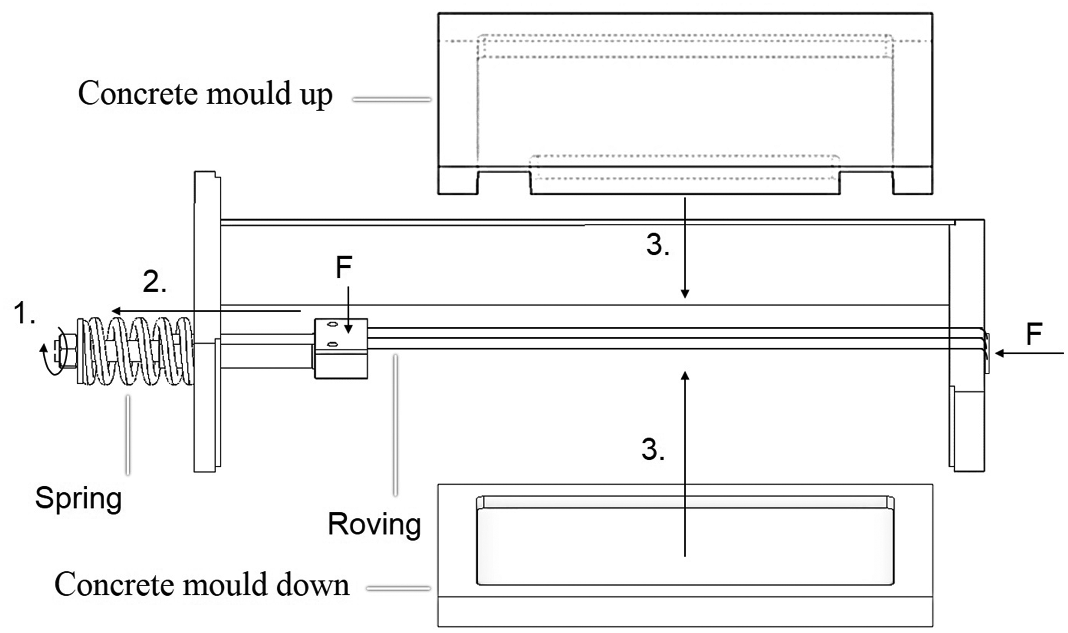
Device for manufacturing of prestressed concrete composite.
The following procedure was applied to overcome the issues. Prestressing was applied using a specially designed frame device. Fixing the units by clamping, epoxy resin, and defection avoided sliding of the rovings over time. The rovings were clamped vertically on the right side between the wall and the steel plate. The coating was applied before loading. Therefore, wetting could be ensured because of good access to the fiber bundle, and curing of the coating occurred on a prestressed yarn. Epoxy resin is applied on both sides of the roving to increase the friction between the roving and clamping plate and to ensure position and avoid sliding of roving over time. On the left side, the rovings were clamped horizontally between dowel pins and steel plates. The rovings are stretched by moving the dowel pins on the left side (2). Therefore, the spring nuts on the left side of the frame are tightened (1). The spring is compressed between the frame and the nut. Force FF was applied to the roving.
Load cells were not used as they contained some disadvantages in fixing the rovings, use over curing time, and curing conditions, as revealed by previous studies. A marker on each roving was used to prove the position over the curing time.
The spring compression (Δx) is measured to define the applied load on the roving, following Hook’s law
FF is determined from the change in spring travel (Δx) and spring characteristic (D). The spring change in length was measured using a caliper gauge. The characteristic of the spring used was 162.45 N/mm, and the number was determined by the manufacturer. A load of 1/3 of the maximum load is applied to the roving, resulting in 1.43 GPa for carbon and 0.57 GPa glass roving. The prestress load was calculated concerning the original roving cross-sectional area.
Thermoset resin is suitable as a bonding agent between individual roving fibers in concrete reinforced composites.23,24 External loads were transferred into all the fibers of the roving by impregnation. The elastic modulus of the epoxy resin used (3 GPa) was one order of magnitude lower than that of the rovings (glass: 72 GPa; carbon: 240 GPa). Therefore, the resin cannot carry the prestressing load, and tensioning must be maintained during the entire hydration process of concrete to introduce a prestressed roving into a concrete part.
The resin was then applied to the roving with a brush. In the following step, two parts of the concrete formwork (3) were attached to the frame, and the formwork was filled with concrete. The concrete formwork dimension was 270x40x20 mm, determined by testing sample standard DIN EN 12390-5 for four-point bending tests of glass and carbon fiber reinforced concrete panels. 25 The reinforcing fibers were positioned at the height of 4 mm.
Fine-grained concrete was used to manufacture composite samples. The mix proportions of fine grain concrete are given in Table 2. The concrete properties are mentioned in numerous publications,26,27 and the concrete specification is called PZ-0899-01. After 28 days of curing the tensile strength is 4.1 MPa, Young’s modulus is 32,200 MPa, and compressive strength is 70.2 MPa. 26
The mass proportion constitutes of fine-grained concrete (kg/m3).

The test samples were kept for 28 d at 23 °C and 95% RH before testing. In Figure 2, an overview of the prestressed fiber-reinforced concrete sample manufacturing process is provided.
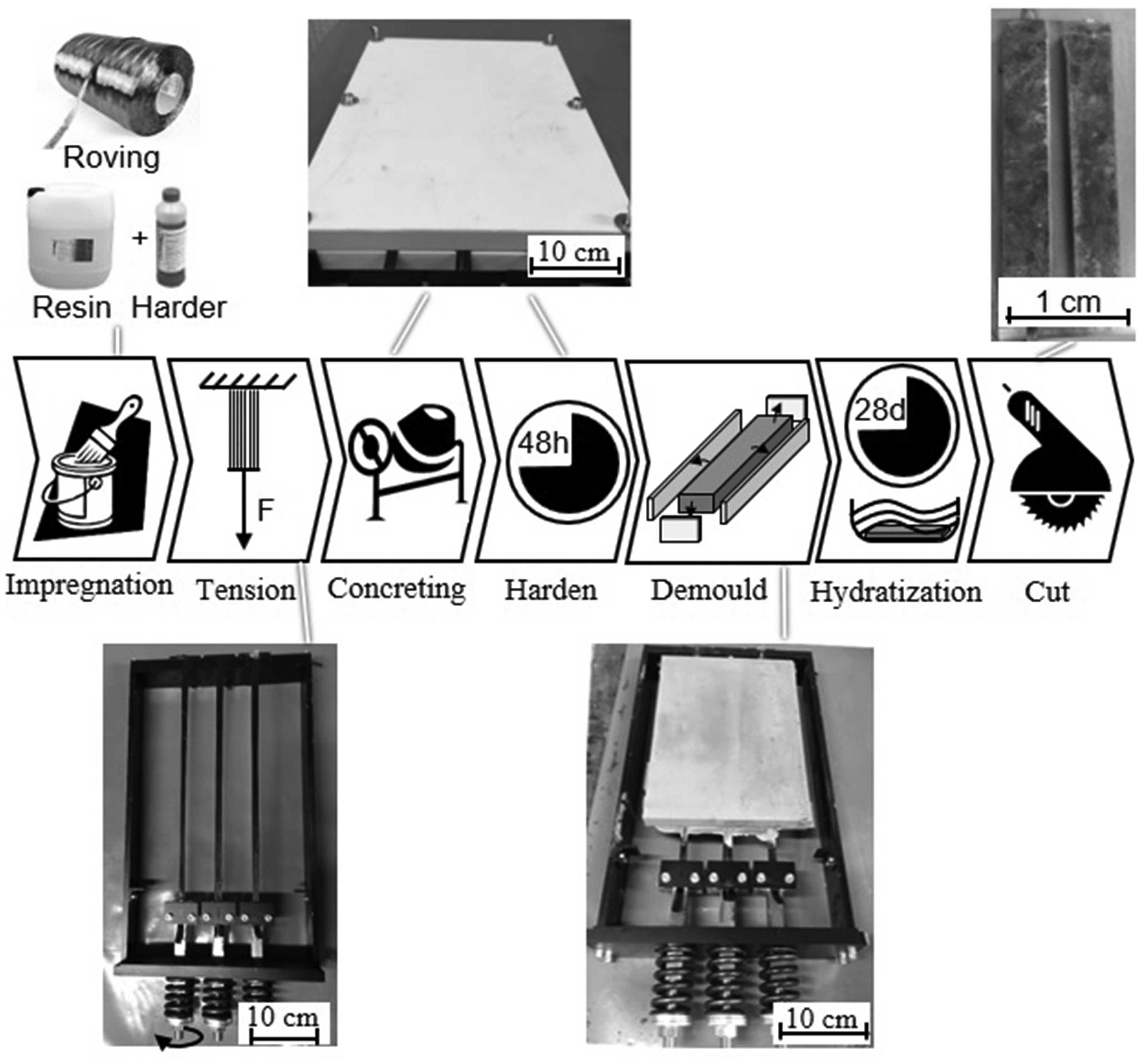
Prestressed fiber-reinforced concrete sample manufacturing process.
Four-point bending tests
Samples of cement composites were tested in a four-point bending test (See Figure 3). The bending tests were carried out following the test methods for fiber reinforced concrete samples according to DIN EN 12390-5 in a Zwick Z100 testing machine at a clear span of 60 mm. The specimens were constantly loaded at a rate of 1 mm/min.
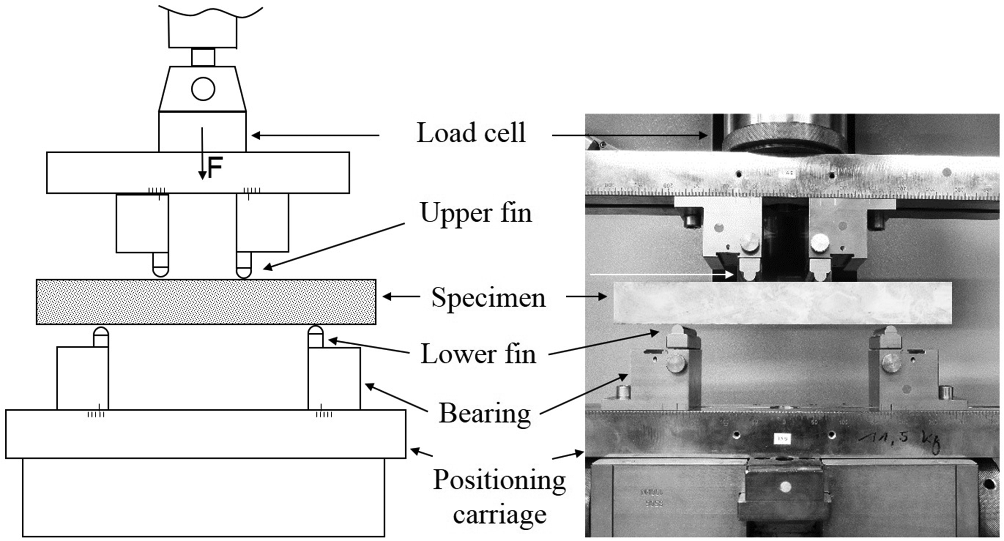
Four-point bending test.
Analysis of roving geometry
The ALPHA ProCon X-Ray computer tomography scanner was used to investigate the roving geometry in the concrete composite. All samples were cut to a size of 2 cm and fixed inside the sample mount. During the scan, the sample rotates while it is scanned by an X-ray. The voxel size in the reconstructed images was 18 µm, and the voltage was 50 kV. The scan was detected using a flat-screen detector. The resulting images were recorded and processed into a 3D image using the software. The scanned image shows the inner structure of the sample. The fiber orientation and distribution of the composite samples were evaluated.
Analysis of the roving cross-section
The roving cross-section samples were examined by optical microscopy to analyze the changes in the roving cross-section shape after prestressing. Glass and carbon roving samples were prepared in the initial (non-prestressed) and prestressed states. Samples for microscopic analysis were prepared using a transparent epoxy resin. The prestress roving samples were prepared directly using the same device used for preparing prestressed concrete composites. After that, the samples were sequentially polished, and microscopic images of cross-sections were obtained using a Leica optical microscope (type DM 4000 M). When processing microphotographs, models of locations of individual filaments inside the cross-section in the coordinate system were obtained. These models allow the determination of the average radius of the filament distribution within the cross-section and the contact length of roving.
The average radius (R) of the filament distribution in the roving cross-section shows the average displacement of the filaments from the center of the roving cross-section, as shown in Figure 4. The average radius was defined by the following equation (19)
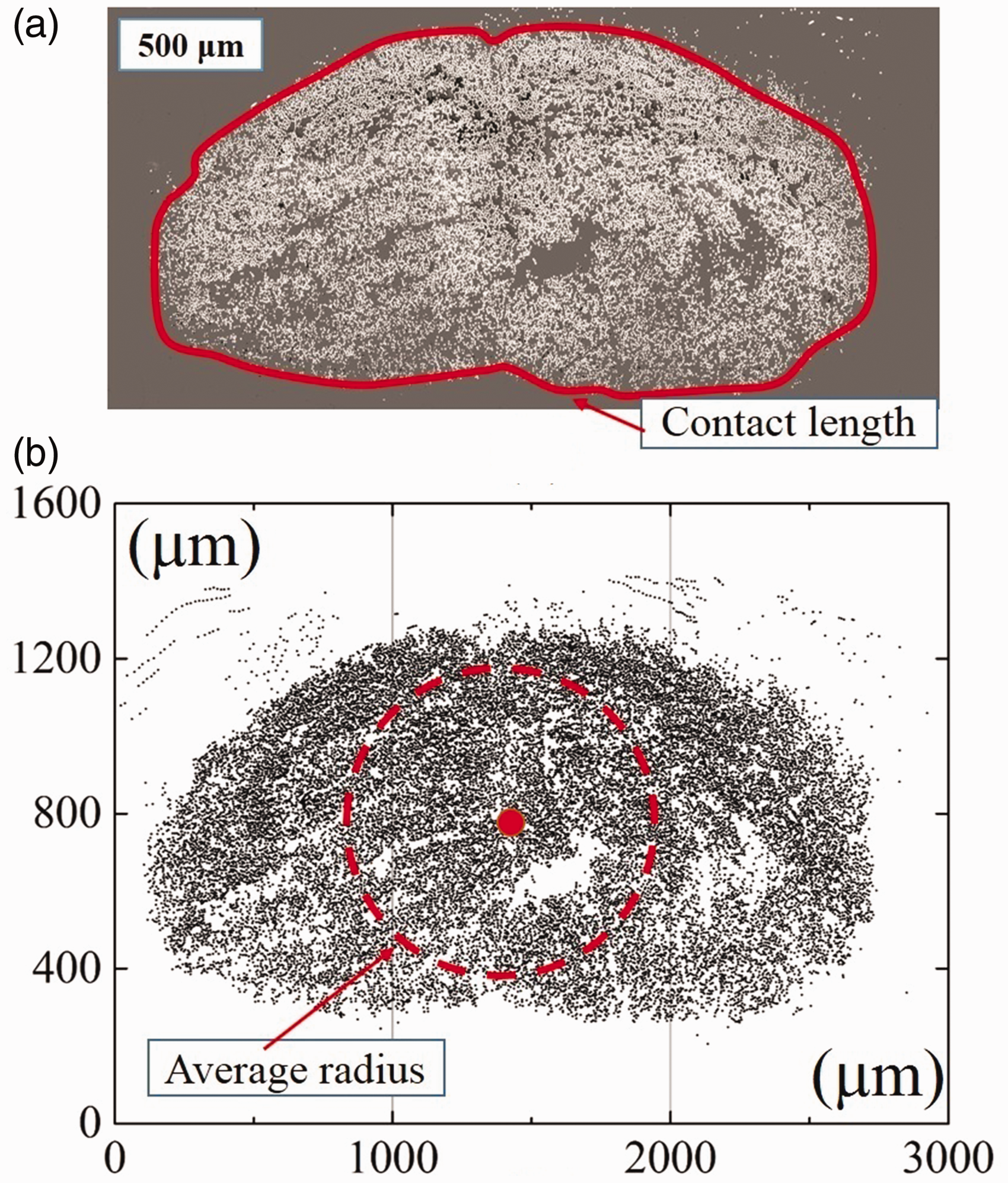
Optical micrograph of a cross-section of carbon roving (a) and its coordinate assignment (b).
The contact length was determined by measuring the perimeter of the roving cross-section. In composite reinforcement, a greater contact length of the roving results in better bonding to the concrete matrix. 19 Figure 4 shows an example of a photomicrograph with a recognized coordinate model and examples of determining the contact length and average radius.
Results and discussion
Reinforcement efficiency of the reinforcement in a concrete composite
The reinforcement efficiency of concrete composites is determined by several factors: (1) their strength at the limit of proportionality corresponding to the limit of linear elasticity and their maximum flexural strength in bending, and (2) the nature of their fracture, including the number of cracks and the width of the crack opening.
Figure 5 shows the flexural stress-deflection curves of four-point bending for samples of prestressed concrete and samples of reinforced concrete without prestressing. The results of the four-point bending test of the composites were taken as a mean curve of six tests for each sample. For the samples reinforced with glass roving (See Figure 5(a)), there is some similarity in the flexural behavior between the reinforced and prestressed concrete. From the curves, it is clear that the behavior of the samples varied. The magnitude of deflection to failure was approximately the same. In this case, the reinforcing roving slips in the concrete until the specimen broke. For the carbon composite, a significant decrease in the achieved deflection was observed (See Figure 5(b)). A prestressed roving specimen exhibits less deflection (approximately 4 mm) at the maximum load compared with a strain deflection of approximately 12 mm for a reinforced composite. After the first crack, the curve of the prestressed sample increased almost linearly till the maximum load. The shape of the curve after the LOP had an uneven shape, which indicated the presence of many other cracks in the sample.
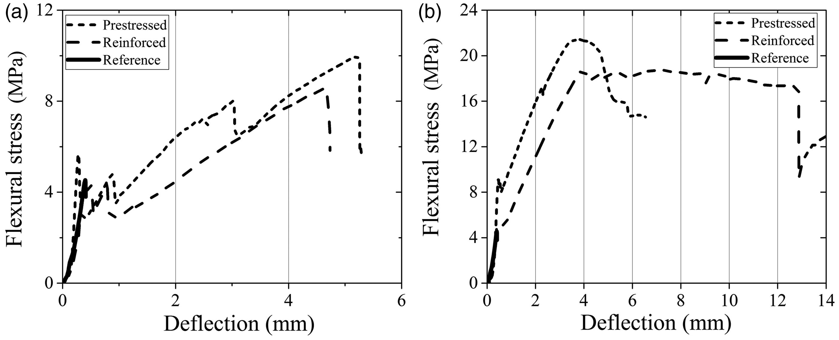
Stress-deflection curve of prestressed concrete composites: (a) glass roving, (b) carbon roving.
The average values and standard deviations of the LOP and MFS are shown in the bar graphs for a series of tests of six samples (See Figure 6). The LOP for a composite reinforced with glass roving is 4.47 and 5.64 MPa for simple reinforced and prestressed samples, respectively. The flexural strength of the prestressed specimen is 10.26 MPa, which is significantly higher than that of the specimen without prestress (8.72 MPa). For samples of carbon roving composites, the proportionality limit is 5.14 and 9.56 for reinforced prestressed, and the flexural strength is 17.55 and 21.6 MPa. Table 3 shows the calculation of the reinforcement efficiency of the prestressed concrete. Thus, the LOP increases by 1.26 and 1.85 times for prestressed concrete samples made of glass and carbon roving, respectively. MFS increases by 1.18 and 1.23 times, respectively. If the reinforcement efficiency is determined with the reference non-reinforced sample, these values will increase significantly. To evaluate the reinforcement efficiency, coefficients that show an increase in composite properties from the original material may be used. The reinforcement efficiency is calculated as follows
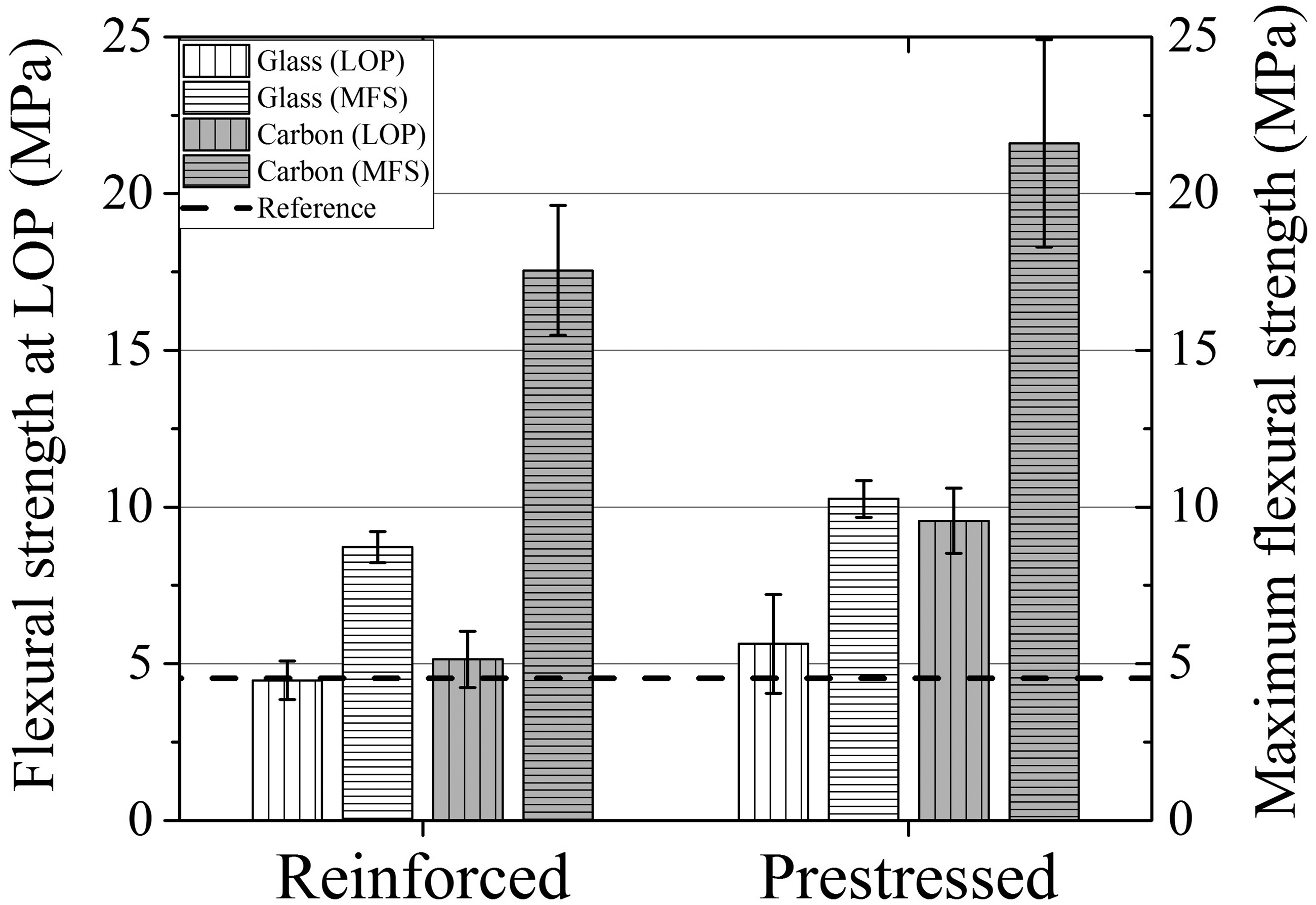
Flexural characteristics of simple reinforced and prestressed concrete.
Reinforcement performance in prestressed concrete related to the non-prestressed concrete (reinforced).

The results are listed in Table 4. For reinforced concrete, the increase for glass roving-based samples concerning LOP and MFS are 1.0 and 1.9 times, respectively, while for samples reinforced with carbon roving, these values are 1.13 and 3.87 times, respectively. Comparing the flexural characteristic samples of prestressed concrete, one can see an increase in LOP and MFS of 1.24 and 2.27 times for glass roving and 2.1 and 4.8 times for carbon roving, respectively.
Reinforcement performance in prestressed concrete related to the reference sample (non-reinforced).

Analysis of the flexural test result
The result of the four-point bending test showed that the strength of the component increased when a prestress was applied to the reinforcement roving. The maximum force that can be applied to the composite and Young’s modulus is significantly higher for the prestressed samples than for the original samples. These results were confirmed for the carbon and glass-reinforced composites. Prestressed carbon specimens have a higher increase in strength than prestressed glass composites. The prestress was released after the concrete was cured. After curing, permanent compressive stress was applied to the composite. In the case of load, this prestress counteracts the applied force, and thus a higher total load is achieved. If the concrete composite was not prestressed, cracks appeared at a lower tensile load. The prestressing of the roving and the resulting stress on the concrete part counteracted the cracking.
The prestressing aligns the filaments into a uniform, parallel, and stretched position. Consequently, the filaments were loaded evenly and simultaneously under a load, which means that the force can be absorbed more quickly. Therefore, the modulus of elasticity of the prestressed specimens is higher than that of the original samples. The force absorption of the glass-reinforced, intentioned rovings is delayed. The flexural strength did not increase immediately. The force absorption of the prestressed specimens is direct. One reason for this is the previously mentioned more uniform and aligned fiber position of the prestressed rovings. The filaments can absorb the forces directly.
Another reason is that the reinforcement in the prestressed composite absorbs the introduced forces before the initial crack. Prestressing puts the component under tension before loading. The fibers already apply a load at this time, and this load is increased when an external force is applied. Consequently, the roving already supports the component before the initial crack in absorbing the external forces and enables the force to be absorbed directly, which is also the reason prestressed samples exhibit a higher flexural tensile stress at the initial crack than unstressed samples. For carbon-reinforced composites, an increase in stress of 85% was observed. For glass-reinforced composites, an increase of 26% in flexural stress was also measured. However, this difference is subject to high fluctuations and must not be considered significant. The force absorption of the reinforcement before the initial crack in the prestressed samples results in less deformation at the initial crack under maximum load and the final failure. Thus, the cracks that occur are smaller or nonessential. Rovings of some glass-reinforced components start to slip at a high deformation (>10 mm) of the component. The angle under which the force was applied decreased and the shear stress increases. The bond forces between the textile and concrete are no longer sufficient to transmit external forces. The components fail not by tearing of the filaments but by the failure of the concrete structure, as shown in Figure 7.
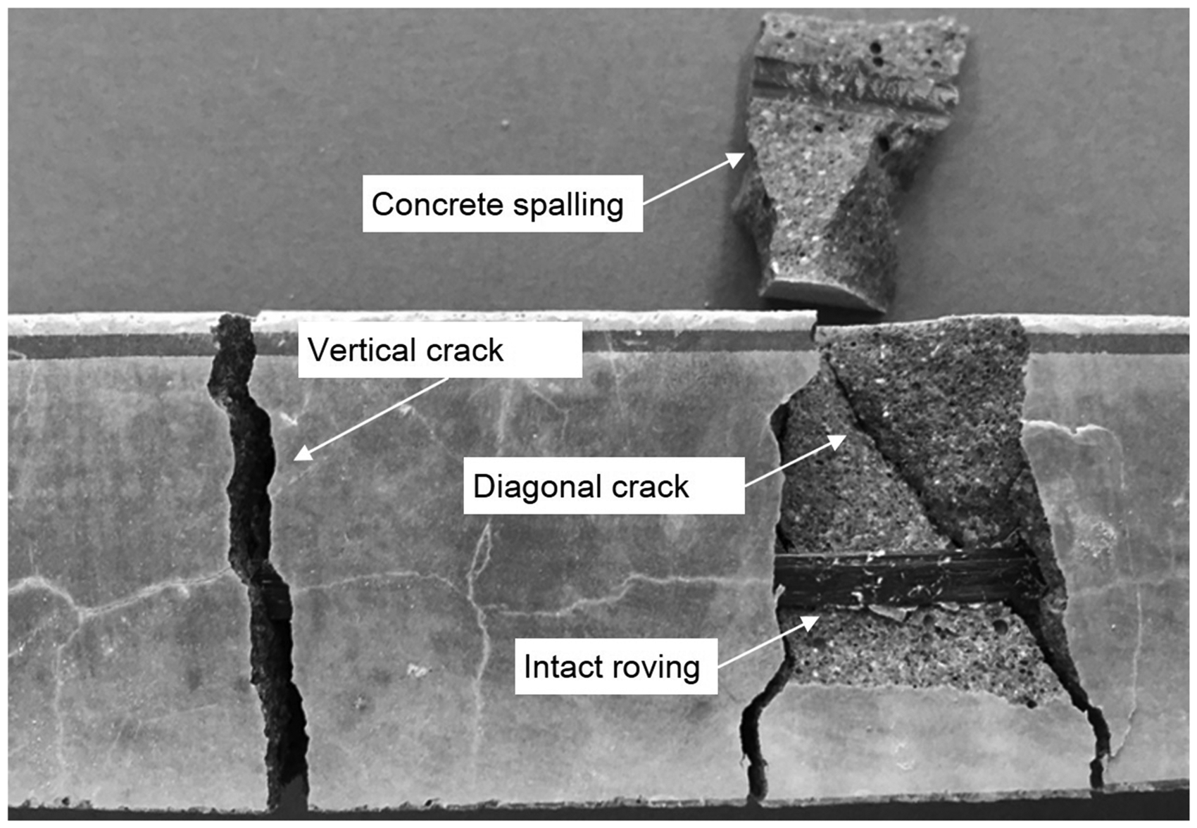
Roving slips unstressed concrete composite.
In Figure 7, a tensionless carbon fiber-reinforced composite can be seen from below after failure. Diagonal cracks develop due to the high compressive stress above the neutral axis of the component and high tensile stress at the bottom of the component. At failure, the component bursts apart, and small pieces of concrete detach. In summary, prestressing increased the component strength by approximately 20% because the fiber layer became uniform, and the reinforcement absorbed forces even before the initial crack.
Results of CT-scanning
The CT scans were applied to samples of prestressed roving, spread roving, and untreated roving. All types were fixed in epoxy resin and introduced into the CT scanner. The CT scans were processed according to the software, resulting in 3D images of the samples. The purpose of these images is to provide a qualitative impression of roving behavior under prestress. The effects of fiber alignment and spreading were visualized. These observations are used to explain the measured results. Figure 8 shows the results of the CT scanning.
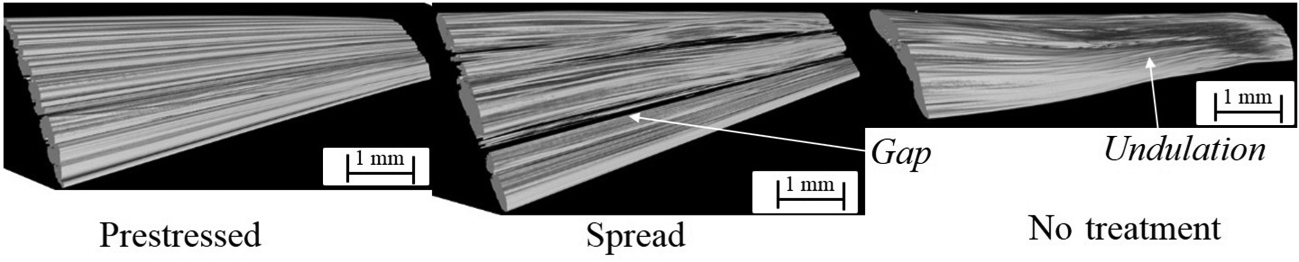
CT-images for all investigated roving samples.
The different pre-treatments caused different alignments of the rovings. Without pre-treatment, the rovings were partly undulated. This undulation is in all dimensions, meaning that the rovings are undulated in the fiber direction as well as in the cross-fiber direction. Spread roving shows partial undulation. However, the degree is much lower than that of the untreated rovings. The spread rovings also showed gaps between filaments. The prestressed rovings show only very little undulation, which is much less than that of the other samples. Further, the filaments were remarkably close to each other. The roving is very compact. It can be correlated that undulations and gaps cause lower mechanical properties because the load is not transmitted into the roving evenly. It also explains the better mechanical properties of the treated rovings.
Effect of pretension on the filament’s distribution in the roving cross-section
The manufacturing of prestressed concrete composites is mainly based on the use of coated rovings. The review showed that non-coated textiles could only have a minimum level of pre-tension, 8 while the coating of roving increases the adhesion of textile reinforcement to the matrix. For the experimental samples, samples of carbon and glass rovings with epoxy impregnation were selected. Figures 9(a) and (b) show the cross-sectional models of the initial and prestressed carbon rovings, respectively. Similarly, Figure 10(a) and (b) show cross-sectional models of the initial and prestressed glass rovings, respectively. The cross-sectional shape of coated roving has an elliptical shape owing to the capillary effect acting on individual fibers upon impregnation. When reeling the supplied roving from the bobbin, it has a flat, flattened shape with a width of several millimeters. Simultaneously, the cross-sectional shape of the prestressed roving changed significantly. Owing to the tensile forces, the roving spreads and becomes flattened because the positioning of the fibers next to each put them into a more energetically favorable condition. Prestressing requires the application of a tensile force. In this case, the fiber was aligned and spread automatically. It is called a “rolling” effect of the individual fibers causes the spreading of the yarn. This cross-sectional shape has a positive effect on the strength efficiency of individual roving filaments owing to a decrease in interfilament friction and an increase in the adhesion surface to the concrete matrix in the composite. The diameter of carbon fibers was in the range of 7 µm while the glass filaments were in the range of 20 µm, which leads to the fact that with a similar cross-section of the roving, carbon fibers contain significantly more filaments compared to glass rovings. The result is a larger contact length, which affects the mechanical response of the concrete composites.
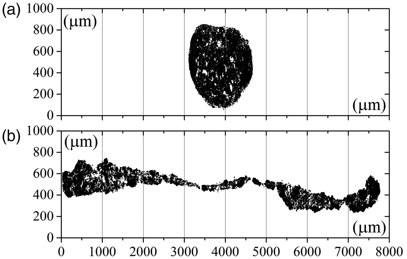
Coordinate assigned models of the cross-section of non-prestressed (a) and prestressed (b) carbon roving.
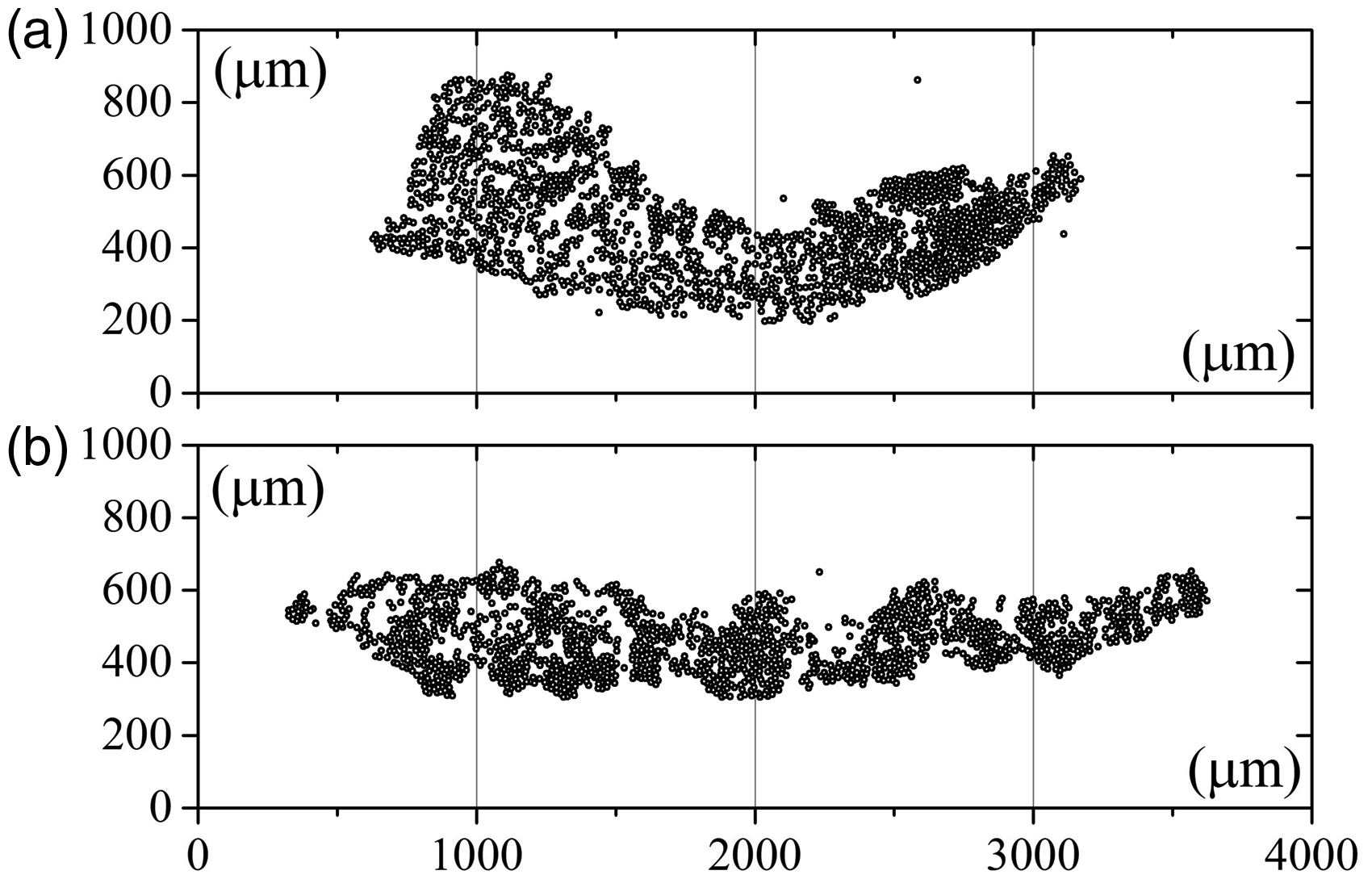
Coordinate assigned models of the cross-section of non-prestressed (a) and prestressed (b) glass roving.
As shown in literature,19,20 the cross-sectional shape of the roving significantly affects both the mechanical properties of the reinforcing textiles 19 and the properties of the composite itself. 20 Two parameters, namely, the contact length and the average radius of the filament distribution, can be used to characterize the properties. Table 5 lists the results of the calculations for the average radius and contact length. The characteristics of prestressed roving are significantly higher than those of non-prestressed roving, which is particularly evident for carbon rovings. If, in the case of glass rovings, an increase in the average radius and a contact length is about 1.3–1.5 times, for carbon roving, the values increase five times on average. Here, the decisive factor is a large number of filaments in the carbon roving, making it possible to move freely. It should be noted here that the increased contact length makes it possible to realize the mechanical properties of reinforcing roving in tension.
The results of the roving cross-section measurements.

The ± terms are standard deviations.
The change in the cross-sectional structure affects carbon roving most of all because of the smaller diameter of filaments and their larger number (tens of thousands) compared to glass strands (about a thousand), which allows a large migration of individual roving filaments, leading to a significant increase in the cross-sectional dimensions of the roving. A large contact length is the main factor affecting the flexural properties of concrete composites.
Analyzing the results of structural changes in the cross-sectional shape of the reinforcing roving and the mechanical characteristics of concrete composites, it can be concluded that the cross-sectional shape of the reinforcing roving is a fundamental factor that affects the realization of the mechanical properties of concrete composites. The relationship between the increase in the average distribution radius and contact length and the mechanical characteristics of the composites for glass and carbon rovings is visible. Therefore, in the case of glass roving, the increase in these characteristics was not as significant as in the case of carbon roving. The proportionality limit of a prestressed glass composite increased by 26% compared to that of non-prestressed glass. In the carbon composite, a significant increase in these characteristics affected the mechanical characteristics. In the concrete composites, they increased by 85%. Thus, an increase in contact length and average radius significantly increases the strength of the prestressed composite.
Influence of the cross-sectional shape of roving on the flexural strength of a concrete composite
Increasing the contact length of the cross-section improved the bonding of the roving to the concrete matrix. In our previous works,19,20 it was shown that the shape of the roving cross-section in the reinforcing fabric depends on the stitch type. For example, in warp-knitted fabrics with inlay rovings, the tricot and cord stitches give a flattened cross-section of the roving, while the pillar stitch leads to the formation of an elliptical, almost circular cross-section. Accordingly, samples of fabrics and concrete composites made with flattened rovings have higher strength compared to reinforcing rovings with elliptical cross-sections. Thus, it was found20,28 that an increase in contact length significantly increases the strength of the concrete composite. A similar conclusion can be made by comparing the cross-sectional shape of the prestressed roving with the cross-sectional shape of the roving in the warp-knitted reinforcing fabrics, as shown for carbon roving in Figure 11. It can be seen that the cross-sectional shape of the prestressed roving is significantly extended compared to the flattened and elliptical roving in the fabric. Therefore, the contact length is more than doubled in the case of carbon roving. For glass roving, this difference was not statistically significant.
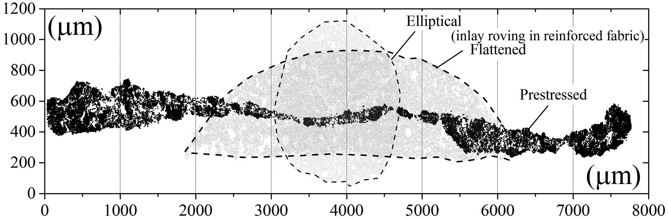
Comparison of the cross-sectional shape of reinforcing rovings in fabric and prestressed roving.
The effects of the contact length and average radius on the flexural properties were quantified. For this purpose, in Figure 12(a) and (b), the dependence of the contact length and average radius on the maximum flexural strength for rovings in the reinforcing fabric 19 and the investigated prestressed rovings are plotted. From the presented dependences, it can be seen that with an increase in both the contact length and the average radius, the flexural strength increases. However, the difference between the flattened and circular sections is not as evident, whereas in a prestressed section, the strength increases sharply. In this case, the greatest growth was observed in the case of carbon roving.
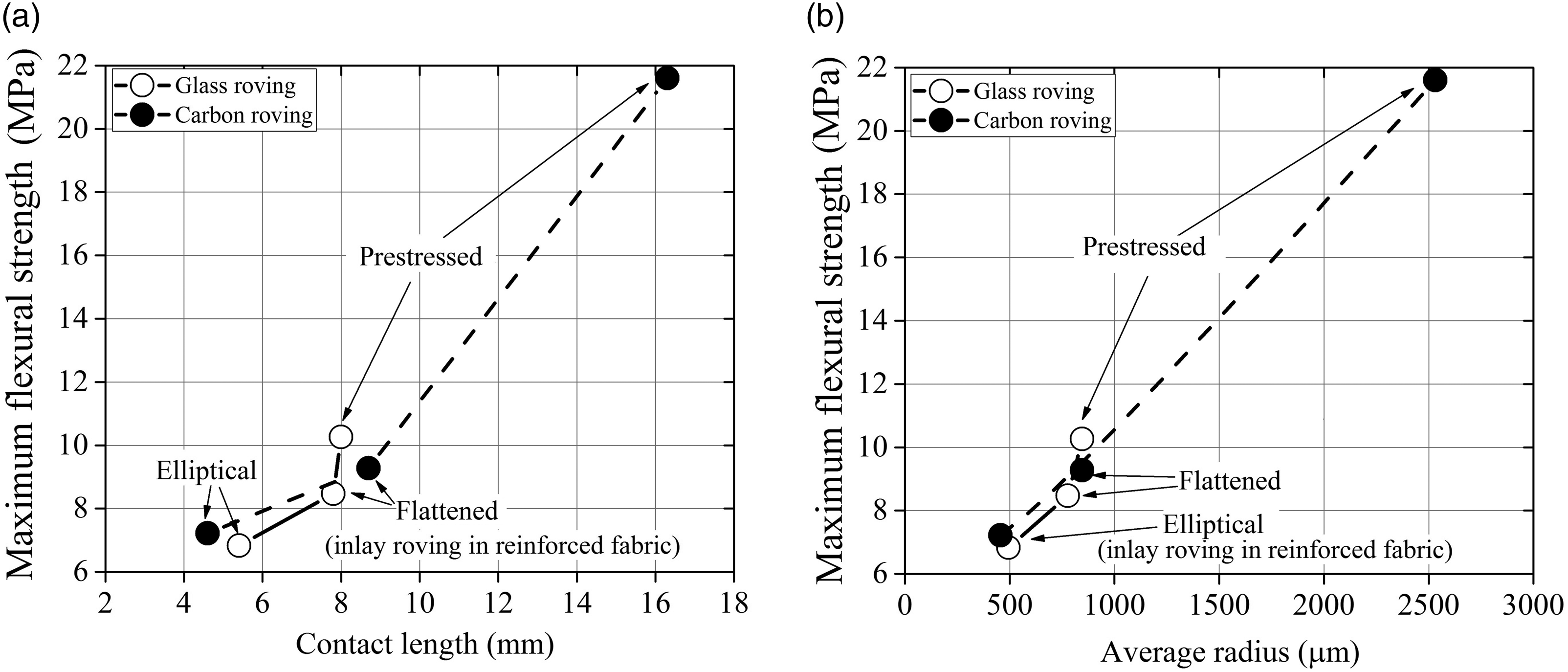
Effect of roving cross-section on the maximum flexural strength.
Conclusions
Samples of concrete composites reinforced with prestressed glass and carbon rovings were manufactured. The prestress level was one-third the maximum tensile stress of the rovings. The flexural characteristics of concrete composites in a four-point bending test were investigated. The results showed a significant increase in the limit of proportionality and maximum flexural strength. The deflection of prestressed carbon-fiber-reinforced concrete is lower than that of non-prestressed composites. For glass-fiber-reinforced concrete composites, the effect is 30% lower because of the higher maximum elongation and lower tensile strength and modulus.
The efficiency of reinforcing prestressed concrete at LOP was 1.26 and 1.85 times higher for the glass and carbon composite, respectively. The flexural strength increased by 1.18 and 1.23 times, for the glass and carbon composite, respectively. The performance of the properties of a carbon composite is higher than that of glass-reinforced concrete.
The change in the cross-sectional shape of the reinforcing rovings in the initial and prestressed states was analyzed. The characteristics of the cross-section, including the average radius of the filament distribution and the contact length of the cross-section, were calculated. Based on these analyses, an explanation is provided for changes in the properties of prestressed concrete.
A quantitative analysis of the shape of the roving cross-section in the traditionally used reinforcing fabrics and prestressed roving was performed. It has been shown that the contact length in prestressed carbon roving is more than doubled. The dependences of the contact length and average radius on the maximum flexural strength showed a sharp increase in carbon roving. However, for glass roving, this increase was not as pronounced.
The change in the cross-sectional structure affects carbon roving most of all because of the smaller diameter of filaments and their larger number (tens of thousands) compared to glass roving (approximately a thousand), which allows a large migration of individual roving filaments, leading to a significant increase in the cross-sectional dimensions of the roving. A large contact length is the main factor affecting the flexural properties of concrete composites.
Supplemental Material
sj-pdf-1-jcm-10.1177_00219983211013382 - Supplemental material for Analysis of reinforcement efficiency and microscopic characterization of glass and carbon roving geometry in prestressed concrete composites
Supplemental material, sj-pdf-1-jcm-10.1177_00219983211013382 for Analysis of reinforcement efficiency and microscopic characterization of glass and carbon roving geometry in prestressed concrete composites by Richard Haas, Till Quadflieg and Oleg Stolyarov in Journal of Composite Materials
Footnotes
Declaration of Conflicting Interests
The author(s) declared no potential conflicts of interest with respect to the research, authorship, and/or publication of this article.
Funding
The author(s) received no financial support for the research, authorship, and/or publication of this article.

References
Supplementary Material
Please find the following supplemental material available below.
For Open Access articles published under a Creative Commons License, all supplemental material carries the same license as the article it is associated with.
For non-Open Access articles published, all supplemental material carries a non-exclusive license, and permission requests for re-use of supplemental material or any part of supplemental material shall be sent directly to the copyright owner as specified in the copyright notice associated with the article.
