






Abstract
Carbon fiber fabrics have been largely used in composite structures as they provide high mechanical strength and potential weigh reduction, allowing more efficiency in product design. However, the production of the parts generates scraps that is discarded as a waste, becoming a challenge to recycle the carbon fiber with predictable mechanical strength. Within this context, this research analyzed strategies of laying up carbon woven fabrics based scraps, in order to reach a desirable mechanical properties in bending loading. Three types of laminates were manufactured using varied fabric size and number of discontinuities in the layup combined with polyethylene terephthalate (PET) film as a matrix. The obtained composites were tested under four-point-bending test and an energy-strength based analysis was conducted. This analysis explained a strategic position of fabric scrap to maximize the bending strength: providing a value of 106.33 MPa for a composite with high number of discontinuities against 83.11 MPa for another with less discontinuity.
Introduction
Fiber reinforced polymer composites have been adopted as a lightweight material for several industrial fields that usually demands high specific mechanical properties and chemical resistance to corrosion.1,2 These attractive properties have led to a mass production of composites which have required high demands for carbon fiber laminates in the past few years. The carbon-based materials have specific properties that are attractive and meet the requirements of the aeronautical sector. Besides, the glass fiber laminates also have been largely used in several fields such as in renewable energy devices for fabrication of blades and nacelles of wind turbines. 3 However, the development and production of composites concurrently implicate in waste generation during the manufacturing process and end-of-life products, that have several restrictions for landfill disposal. 4 In addition, the waste material is mostly derived from polymers that may end up affecting the environment as, for example, contaminating fresh water and soil. 5
Due to the restrictions to dispose polymer composites, several researchers from technological institutes and industries have been focused in obtaining transformed or reprocessed material with new attractive features with minimum loss of properties, and use the minimum energy intensity.6–8 In such a way, carbon fiber scraps from cutting operations have been attracting researchers attention for reprocessing purposes, aiming at reaching attractive mechanical properties, that are inevitably reduced as they depend on the integrity of the fiber such as fiber length. 8
The reduction of composite property mostly relates to the fiber length reduction as a consequence of reclaimed end-of-life composites, or ply cutting operations (scraps), where the use of short fiber with random distribution has led to laminates which exhibit interesting mechanical properties.1,9–11 Kouparitsas et al., 12 for example, compared three different recycled fiber with virgin fiber, and verified almost the same mechanical behavior in tensile tests with values for ionomer/carbon fiber of 20 MPa in tensile strength and 400 MPa of axial modulus. Turner et al. 13 worked with short fiber within the critical length range (1-10 mm), and emphasized the importance of the fiber length in the mechanical properties. Feraboli et al. 14 reused carbon fiber as extracted from a thermoset composites in a form of continuous reinforcement, but randomly distributed. For this type of composite with fiber length well above the critical length, the flexural strength reduction was about 47.57%. Composites with randomly distributed fibers have their mechanical properties reduced by 91.40% using a fiber length of 3 mm. 15 Liu et al. 16 mentioned the difficult task of homogeneously disperse chopped fiber to obtain high mechanical properties. In this case, the authors achieved a bending strength between 55.6% to 65.8% of a continuous laminate composites, working with chopped fiber length between 15 to 45 mm. The decreasing fiber length impacts in flexural properties such as reported by Pietroluongo et al., 17 providing a bending strength of 187.7 MPa and a bending modulus of 6.83 GPa using an average fiber length of 253 µm from a recycled glass fiber dispersed in a PA66 matrix. This work has the advantage of using an injection molding machine that improves the homogeneity, and consequently, it reduced the scatter of the mechanical properties.
The literature has reported a natural reduction in mechanical properties of discontinuous recycled fibers used in composites, reaching reasonable mechanical properties nevertheless. However, most of the works have not reported the effect of the layup and scrap size of the recycled/reused carbon fiber on the mechanical properties. In order to understand this effect, and provide some guidelines on how to improve the mechanical performance of fabric scraps, this research evaluated three types of laminate with several scrap size and fabric architecture by conducting four-point-bending tests, as this test setup provides maximum constant moment along the discontinuities. The analysis of the tested specimen behavior was based on the classical beam theory.
Materials and methods
Materials and process
The waste material consisted in a dry woven fabric in the form of harness satin (5HS), which has HTA carbon fiber with 6 K filaments provided by TENAX, resulting in a final areal weight of 375 g/m2.
The stacking sequence comprised 10 plies resulting in two types of laminates with 58% of fiber volume fraction: without ply discontinuities (reference material); and with a controlled number of ply discontinuities (defined as recycled laminate). The stacking sequence of (0,90) fabric plies was alternated with polymeric matrix film, always keeping the warp in the outer side of the ply and the 0° fiber aligned to the principal load direction (maximizing the flexural strength). The polymeric matrix film consists of a saturated polyethylene terephthalate (PET) film provided by Toray with nominal thickness of 125 μm, and a melting temperature onset of 239.63 °C. Differential scanning calorimetry analysis (DSC) was carried out to find the thermal transitions, as shown in Figure 1.
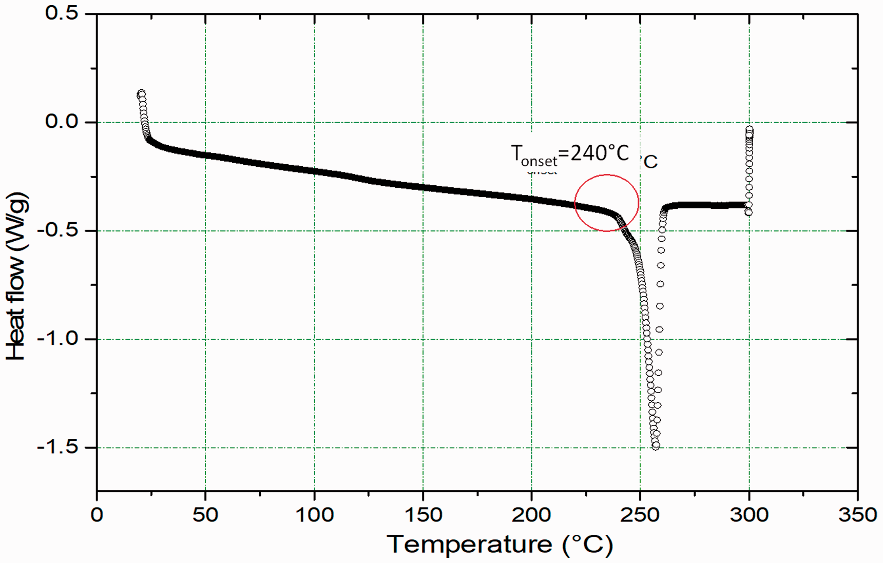
DSC profile of PET – S10 material provided by Toray.
The employed thermoplastic film is commercially available and it has high reprocessability which meets some of the sustainable requirements for design purposes. An excess of 20% (m/m) of thermoplastic film was adopted to overcome eventual losses of resin during the process, which was around 4% (m/m). In order to certify the homogeneity of the resin throughout the fiber preform, thermography and ultrasonic test (pulse-echo) were conducted. The whole plate did not present any hot spot that may represent a defect or dry spot.
The laminate composite was processed with compression molding technique with a processing cycle depicted in Figure 2(a), and in Figure 2(b) shows the fabric preform in the mold.
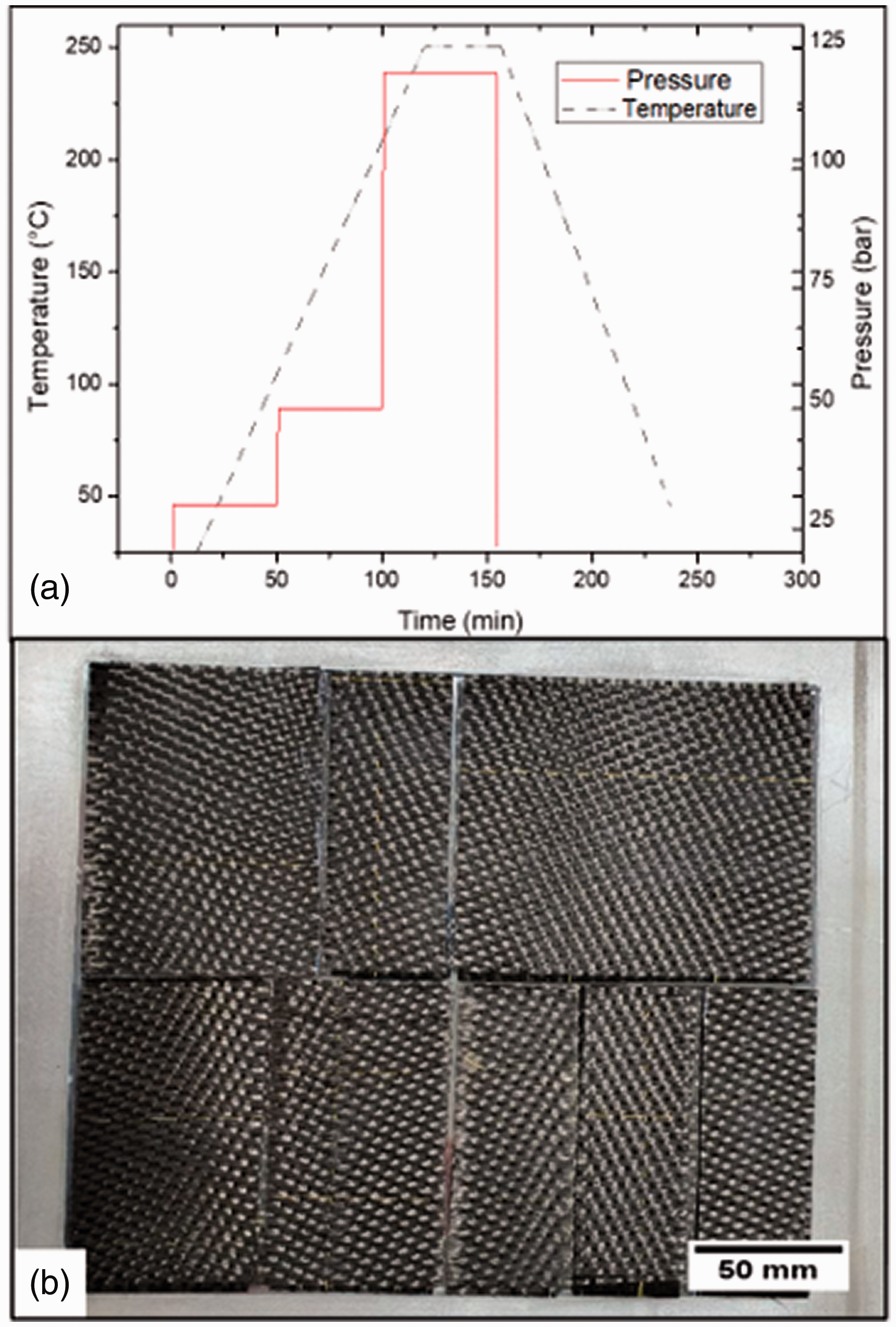
Compression molding: (a) temperature and pressure cycle; (b) molding cavity with discontinuous fabric scraps.
Fabric layup and disposition
The layup sequence and position within the laminate were defined according to the waste size available. A discontinuous ply was always positioned in between two continuous section of fabric, thus avoiding two consecutive plies with discontinuity in the same position. This strategy was adopted in order to optimize the interlaminar loading transfer, as shown in Figure 3.
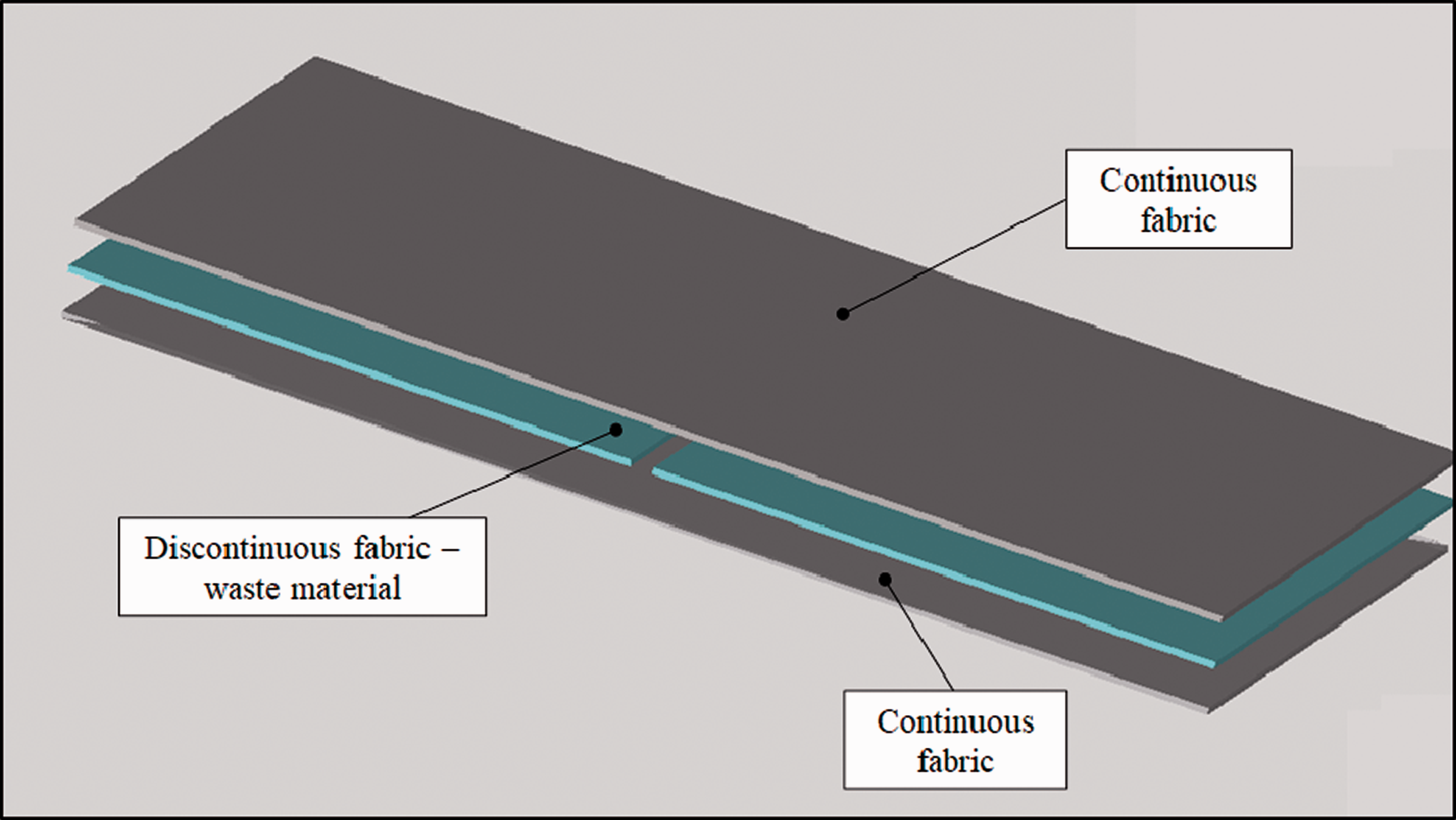
Fabric superposition strategy.
Figure 4(a) shows the distance between interrupted ply and loading span (four-point-bending), and Figure 4(b) to (d) indicates the distance between loading span and the discontinuities. The discontinuities are positioned in a region of maximum bending moment that is equal to

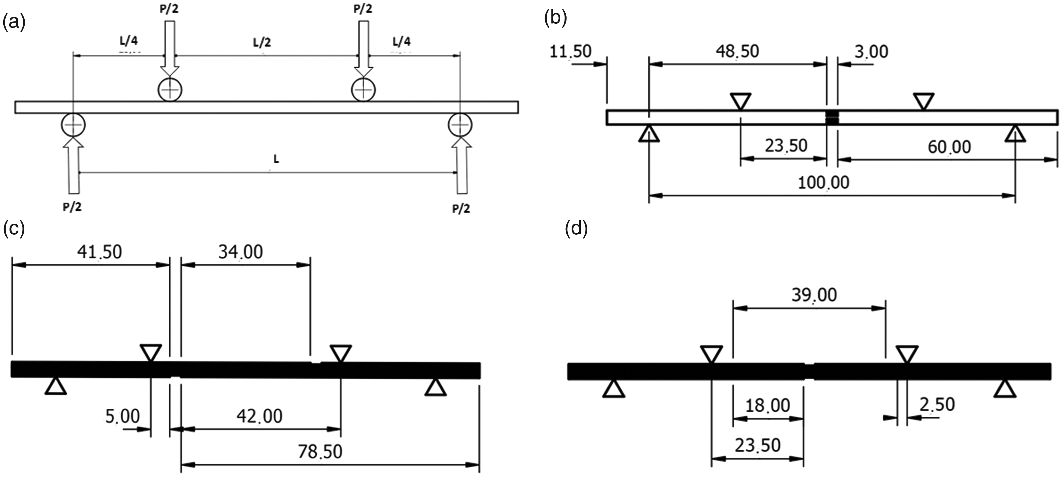
Interrupted ply position and dimensions in relation to loading span: (a) test set up; (b) 4 interruptions; (c) 10 interruption; and (d) 14 interruptions.
Detailed quantity and size for the laminates.
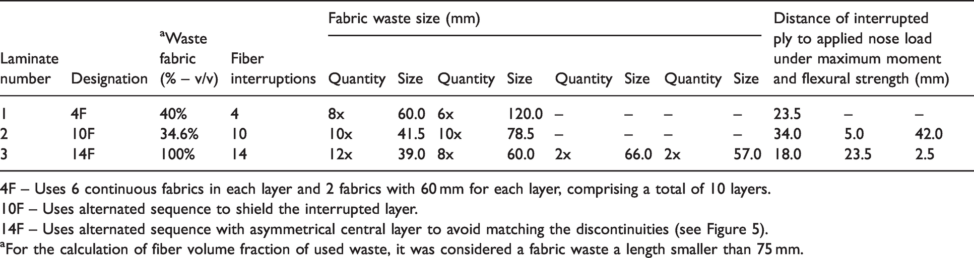
4F – Uses 6 continuous fabrics in each layer and 2 fabrics with 60 mm for each layer, comprising a total of 10 layers.
10F – Uses alternated sequence to shield the interrupted layer.
14F – Uses alternated sequence with asymmetrical central layer to avoid matching the discontinuities (see Figure 5).
aFor the calculation of fiber volume fraction of used waste, it was considered a fabric waste a length smaller than 75 mm.
where σf is the flexural stress, M the applied moment, w is the specimen width, t is the thickness, y is the distance from the neutral line, and I the moment of inertia. For the maximum flexural strength, it is considered y = t/2.
The strategy to keep the discontinuity always shielded by a continuous ply yields to varied fabric scrap lengths and quantities, as shown in Table 1. For example, laminate 10 F has one discontinuity in each layer, and for this ply there are two fabric scrap with different sizes, resulting in 20 pieces of fabric scrap. This particular laminate has this difference in size to avoid matching two consecutive interruption by shielding it, in this respect, it was necessary to have asymmetric interruptions. The other two laminates have symmetry in the montage, thus avoiding any type of coupling.
Each laminate was cut in the form of retangular shape with dimensions of (13x110x4) mm as shown in Figure 5, keeping the discontinuities between loading spans for correct evaluation of flexural properties. The four-point bending tests were carried out following standard test method ASTM D7264/D7264M-15, 18 with displacement rate of 1 mm/min and testing five specimens in each condition. A servo-mechanical testing machine was employed with a 5 kN load cell and a strain-gage was bonded at the outer face of the beam to monitor the strain. The force and strain data were acquired and post-processed to calculate the stress-strain curves using equation (1).
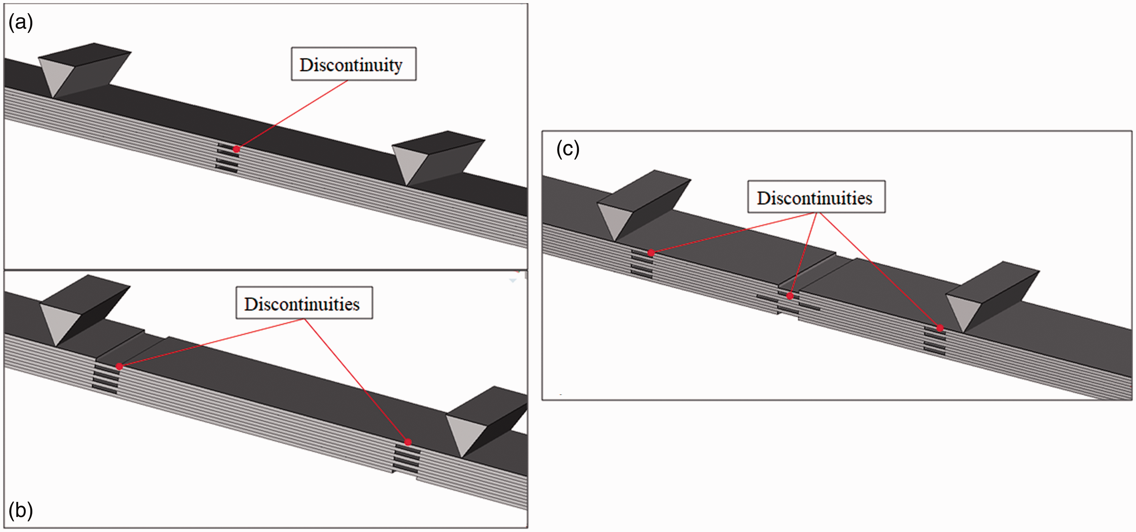
Detailed view of the stacked sequence: (a) 4 interruptions; (b) 10 interruption; and (c) 14 interruptions.
Results and discussion
Flexural strength approach
The maximum flexural strength (σmax) of the laminates progressively decreased according to the increase in number of fiber discontinuities from 0 to 10. The flexural strength of the reprocessed waste composites have a reduction of 33.34% for 4 F, 55.58% for 10 F, and 43.17% for 14 F in comparison to the continuous composites. Nevertheless, a good strategy of layup design is evidenced by using laminate 14 F with more discontinuities, which in turn exhibited a better mechanical performance than laminate 10 F. For example, the maximum flexural strength of laminate 14 F is higher than the one obtained for laminate 10 F, despite the reduced size of scrap length and the high number of discontinuities, as seen in Table 2. In addition, as depicted in Table 1, laminate 14 F uses 100% of fabric waste with reduced size, while laminate 4 F uses 60% of virgin carbon fiber in its layup. Regarding the associated total elongation of the discontinuous laminates, no significant differences were observed in the elastic region, as a result of the induced failure by the interrupted ply, as shown in Figure 6(a). The induced failure at the discontinuity is a result of a local increase in interfacial shear stress adjacent to the continuous fibers, 19 that consequently limits the deformation. Figure 6(a) shows a representative behavior of each laminate design, in which the specimens did not separate due to the ductile nature of the thermoplastic matrix.
Flexural Strength of the laminate types.

CV – coefficient of variation.
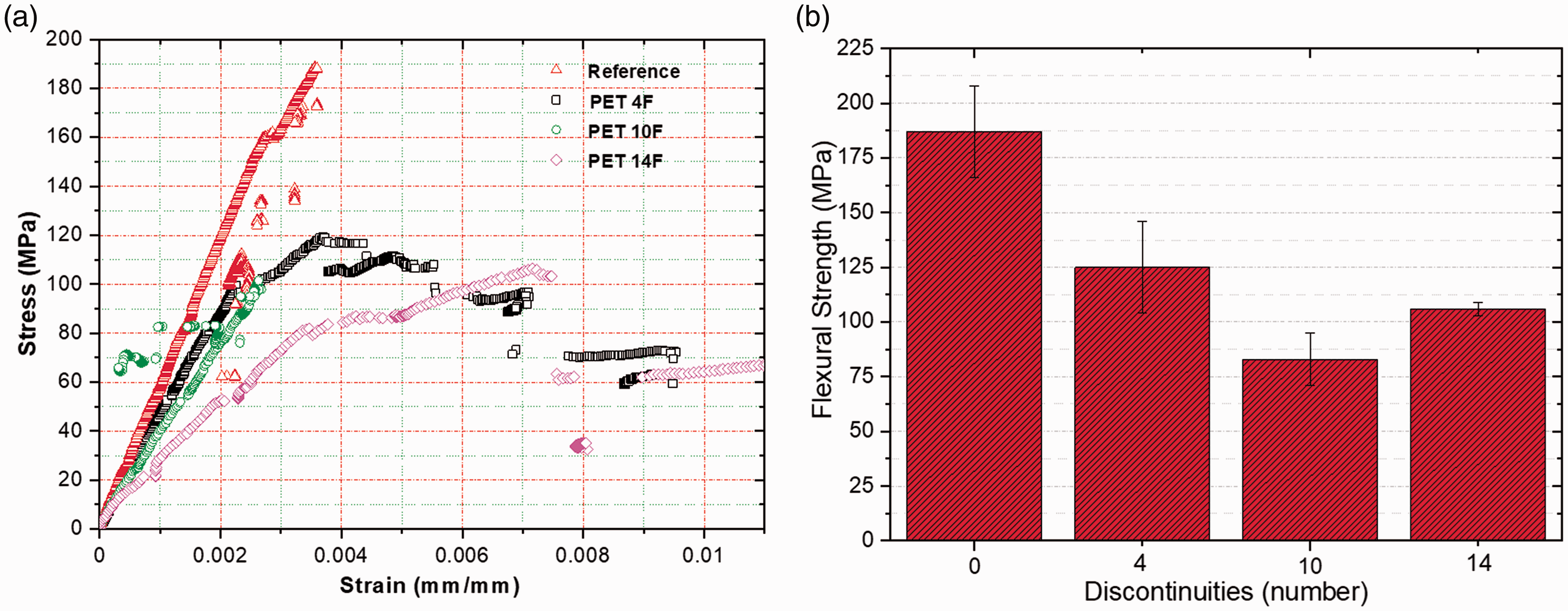
Flexural strength: (a) stress-strain curve; and (b) stress as a function of number of discontinuity.
The correlation between maximum flexural strength and number of discontinuities is shown in Figure 6(b). Results of laminate 14 F showed a low standard deviation in which is attributed to a well-defined failure location due to the nonuniform stress state adjacent to the discontinuity. 19 This well-defined failure relates to the discontinuity position of the Laminate 14 F, at the middle of the specimen, where a maximum bending stress is at the outer fibers, according to equation (1), thus enhanced the flexural strength. On the other hand, higher standard deviation results were observed for laminate 10 F showing that a failure can be either at the last ply or at the neighboring ply, in which did not reach the maximum flexural strength. The variation in standard deviation due to the quality of the laminate is discarded as they were processed in the same batch.
Figure 7 presents the dependence of maximum flexural strength as a function of the discontinuity position in relation to the first and second layers (i.e. the distance between the position of the support span and the middle of the beam). For example, Laminate 14 F presents the discontinuity of the first ply at the middle of the beam (outer fiber at tensile – empty circle), while the discontinuity of the second ply is near to the loading nose (crossed circle). This representation reveals the influence of the outermost plies (first and second plies) on the failure process, as they are under maximum flexural stress, considering also that two variables are under evaluation regarding the mechanical properties: total number of discontinuities and their position.
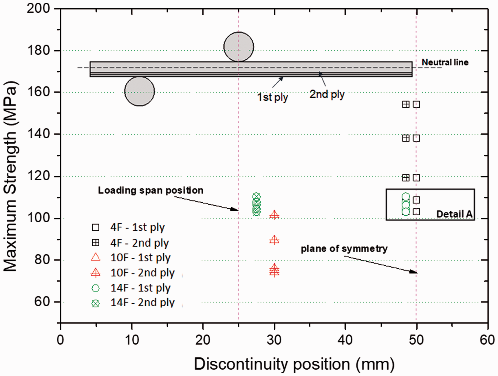
Dependence of flexural strength on the applied bending moment.
For Laminate 4 F, half of the maximum flexural strength values lies close to the strength values obtained for laminate 14 F, see Detail A in Figure 7. This similarity in flexural strength behavior can be attributed to the location of the discontinuity at the center of the beam, where failure took place: laminate 4 F has a discontinuity at the second ply; and laminate 14 F has a discontinuity at the first ply. The flexural strength in laminate 4 F is related to the second ply failure process due to the discontinuity effect, in which shear stress becomes high at the vicinities of discontinuity and axial stress decreases (responsible for the flexural strength), 19 thus decreasing the loading carrying capacity. For this particular laminate design, the loss of flexural strength was minimum (33.34%) as the first ply is continuous (virgin material). This analysis was supported by failure (fractography) analysis, as depicted in Figure 8(a), where specimens failed by buckling in the first ply in Laminate 4 F, with values above 124.73 MPa, in which a continuous ply hold the maximum compression stress.

Failure modes in discontinuous composites: (a) 4 F; (b) 10 F; and (c) 14 F.
Laminate 10 F exhibited the lowest flexural strength among the three laminates as the failure was driven by the first ply, where the discontinuity was positioned closer to the loading span, which modifies the loading transfer, as will be discussed in the next paragraph. This laminate exhibited a generalized failure in all plies as shown in Figure 8(b). The reason for superior performance of Laminate 14 F is also related to the process of loading transfer, that allows to withstand higher stress than Laminate 10 F due to the proximity of the discontinuity to the middle point of the beam. Thus, the elastic energy is even distributed throughout the beam. Besides tensile failure, the fiber architecture (woven) also induces failure by buckling in the compressive section of the beam, limiting the maximum strength, as seen in Figure 8(c).
The combination of uneven elastic energy in Laminate 10 F and the maximum load in the last ply yielded to a low flexural strength. The reduced scrap dimension required to overlap a discontinuous ply leaded to an uneven energy distribution in between first and second ply, where maximum bending moment and maximum stress are located, which overloads the discontinuous section yielding to matrix failure. The demonstration in terms of energy can be carried out by integrating equation (2)20 along the beam that leads to the total elastic energy

Where in equation (3), dV can be replaced for Bdydx, in which Bdy is the cross-section area of the ply. Equation (3) represents the total energy of the beam, and to consider the energy of the single ply for evidencing the difference in energy distribution of laminates 10 F and 14 F, y is taken from the outer surface of the beam to the next ply (measured from the neutral line). Then equation (3) can be integrated and an energy associated to the last ply is obtained in the form of
The region under maximum applied moment, where the discontinuities are located, concentrates 75% of the total elastic strain energy of the beam. It was calculated by taking the second term of equation (4) and dividing by the total elastic strain energy of the beam. This elastic energy stretches the fibers and the matrix at the interface. At the fiber discontinuity, it causes a decrease in the interlaminar load transfer capacity assuming failure at the interruption, this event yields to an energy concentration at the scrap section followed by failure. It can be estimated by using the energy per unit length (Uply/ls), calculated as the ratio between elastic energy hold by the ply (Uply) and the distance between loading nose and first discontinuity (ls). The high energy ratio (Uply/ls) indicates an overload at the scrap section due to interrupted shear stress in the last ply, as shown in Table 3. Table 3 includes the total energy of the beam, determined from a plot of force versus displacement curve, obtained in the experimental tests. The calculations take into account the elastic strain energy up to 100 N within linear region of force versus displacement curve, where all the equations are still valid.
Results of elastic strain energy of the beam.

The energy ratio (Uply/lc)) in Laminate 4 F was considered for the second ply as the last ply was continuous, but it did affect the failure as previously showed in Figure 7. In addition, due to the higher flexural modulus, the deflection was reduced, consequently it presented the lowest strain energy. Despite the increasing value of elastic strain energy (laminates 10 F and 14 F) associated to a more flexible beam, this was not necessarily associated to maximum flexural strength, as also shown in the third column of Table 3 as compared to results of flexural stress presented in Table 2.
The variation of flexural stress along the y axis is shown in Figure 9 for laminates 10 F and 14 F. The difference in stress distribution has a negative influence on the flexural strength for Laminate 14 F. Besides the stress peak at the discontinuity, higher shear stresses are expected due to the plies stiffness mismatching induced in regions with different number of discontinuities. This difference in flexural stress in the transition from outer ply to neighboring ply is explained by different flexural modulus for those laminates, as seen in Figure 9(a). In order to accounted for these differences, the stress 
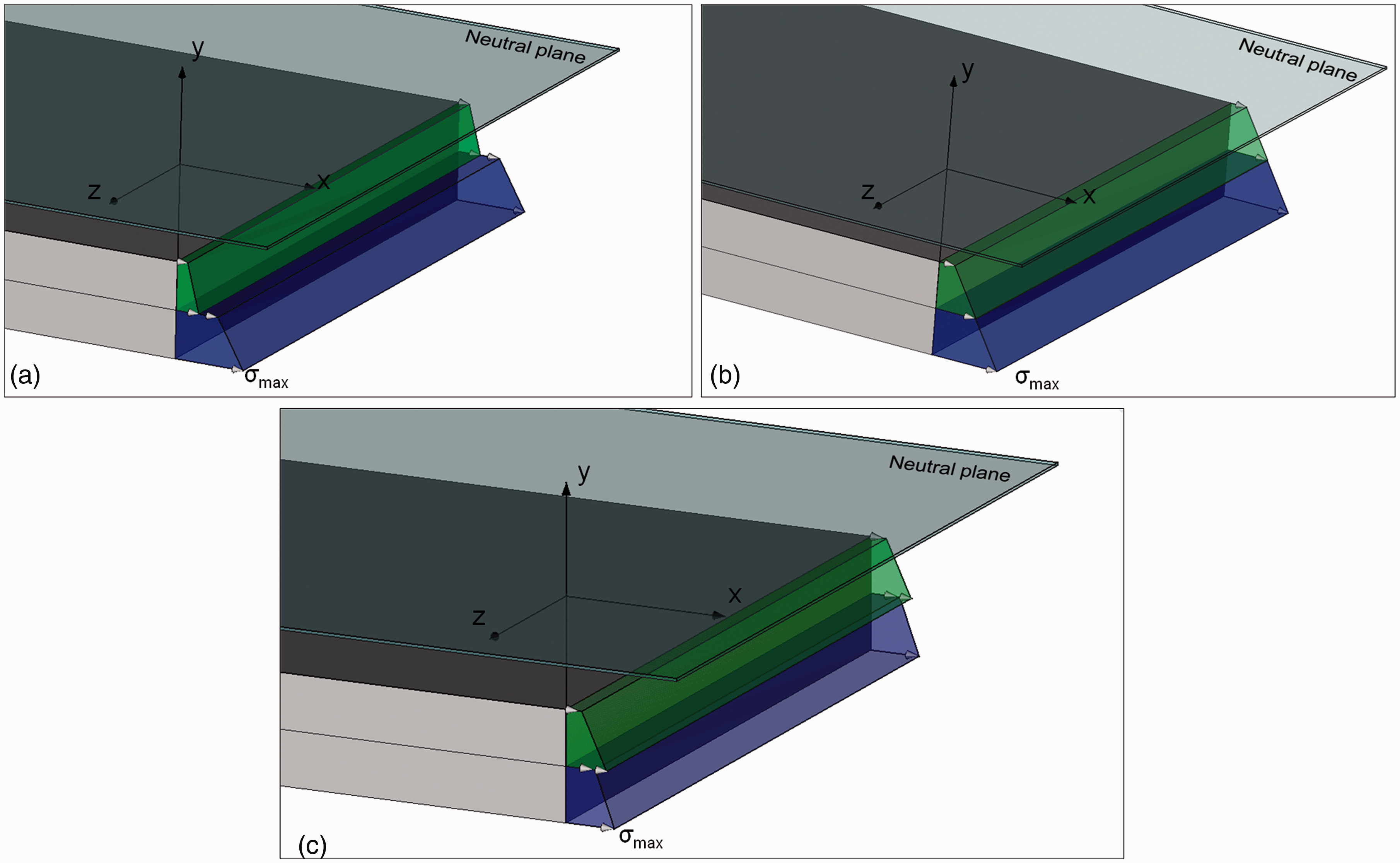
Flexural stress along the y axis: (a) laminate 14 F; (b) ideal distribution for laminate 10 F; and (c) real distribution due to asymmetry in laminate 10 F.
where E is flexural modulus, 
The reduced modulus of the second ply (E2F) in Laminate 14 F allows the outer fiber to deform at the limit of matrix strain at the joint section of the first ply, reaching maximum stress, by taking into account the analysis of the zy plane of symmetry at the cross section in the middle of the beam. Laminate 10 F, for instance, has 10 plies with equal modulus (E1F) leading to
Flexural modulus behavior
From Table 4 it can be seen how flexural modulus decrease with an increase in the number of discontinuities. The increase compliance of the plies results in a maximum reduction of 56.36% of flexural modulus which is related to laminate 14 F, explained by the increase number of fabric discontinuities: total of 14. The reduced modulus does not indicate an increased deformation, instead laminate 14 F has reduced deformation as compared to laminate 10 F. As verified in the discussion of flexural strength, the deformation in discontinuous laminate is related to the failure location.
Results of flexural modulus of the laminates.

The flexural modulus (E), reported in Table 4, was obtained by taking the slope of the stress-strain curves as shown in Figure 10(a). A plot of the E values versus the discontinuity numbers (n), it can be seen that the flexural modulus decreases linearly with n, depicted in Figure 10(b).
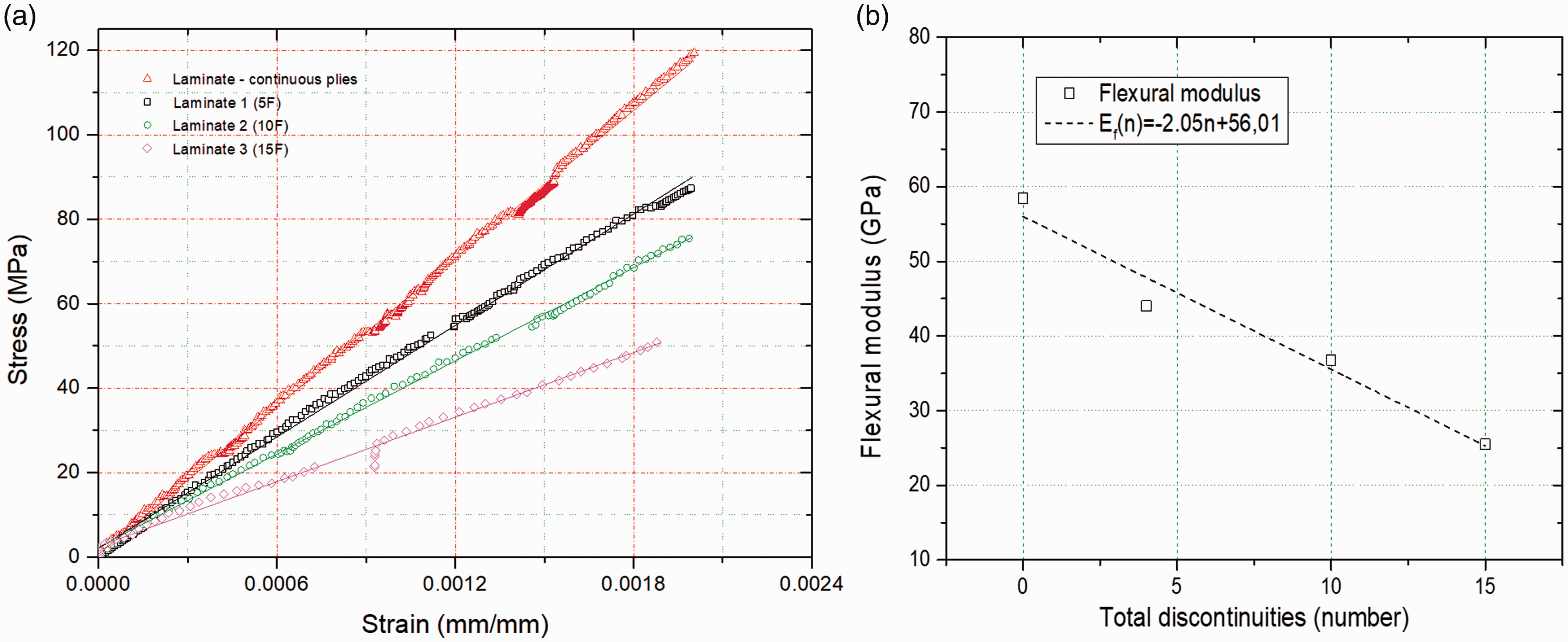
Experimental data: (a) stress (maximum at outermost fiber) versus strain; and (b) flexural modulus of the laminates.
The flexural modulus is less sensitive to the discontinuity position, when compared to the maximum flexural strength values. The decreasing angular coefficient relates to increasing flexibility of matrix within plies due to the fabric discontinuities, which allow additional deformation along the beam in the limits of elastic region. This deformation can be constrained by an adjacent stiffer ply. Considering the ply superposition strategy to shield the fabric interrupted section, the laminate has a more predictable behaviour in terms of flexural modulus.
Conclusions
Experimental results obtained for laminate composites manufactured with carbon fiber fabric scraps indicated that the maximum flexural strength depends on discontinuity position, and partially depends on the number of discontinuity. Such dependence was demonstrated by analyzing the discontinuity position away from the neutral line, that is, at the outer surface of the beam. By considering the elastic strain energy and strength analyses, the product design with scraps can strategically met the strength and stiffness requirements by selecting the available scrap dimensions. Thus, in this research, fundamental equation of strength of materials enabled to elucidate failure causes in heterogeneous materials, within the limits of linear elastic behavior. The stress distribution also played a fundamental role in obtaining maximum flexural strength in discontinuous laminates.
In addition, compression molding with thermoplastic polymer, like PET, can also provide high-rate production, for example, in automotive industry evidencing the importance of taking advantage of high amount of waste with efficient manufacturing process.
Footnotes
Declaration of Conflicting Interests
The author(s) declared no potential conflicts of interest with respect to the research, authorship, and/or publication of this article.
Funding
The author(s) disclosed receipt of the following financial support for the research, authorship, and/or publication of this article: The authors received the financial through grants #2017/16160-8 and #2019/26312-5 of São Paulo Research Foundation (FAPESP) and CNPq grant No. 301069/2019-0.
