
Abstract
The stress-strain responses and damage initiation/propagation mechanisms of T700G/LM-PAEK, an open-hole carbon-fiber-reinforced thermoplastic were investigated experimentally and numerically. To obtain the mechanical properties necessary for numerical simulations, uniaxial tensile/compressive, double cantilever beam, and end notched flexure tests were conducted. T700G/LM-PAEK was found to have comparable or higher Young’s modulus, strength, and interlaminar fracture toughness relative to thermoset CFRPs with carbon fiber of a similar grade. These superior mechanical properties are mainly attributable to the higher toughness and ductility of the thermoplastic resin. The interfacial fracture toughnesses were evaluated by finite element analysis with the cohesive zone model to determine the interlaminar fracture toughnesses for crack initiation and propagation. Based on the above experimental and numerical results, the stress strain response and damage evolution of open-hole specimens were analyzed by a quasi-3D extended finite element method (XFEM) and compared with the experimental results. The computational model with the elastoplastic constitutive law provided an accurate prediction of the stress-strain response in both open-hole tension and compression (OHT and OHC, respectively), suggesting that the elastoplastic constitutive law should be considered in XFEM to guarantee the accuracy of strength prediction for both OHT and OHC. The OHT model showed that the Weibull criterion was satisfied without any delamination at the failure strain, corresponding to the brittle failure mode due to fiber breakage. For the OHC simulation, the damage initiation of 0°-ply kinking was observed at 88% of the peak stress. These predicted damage mechanisms agreed reasonably well with the experimental observations.
Keywords
Introduction
In the last 20 years, carbon-fiber-reinforced plastics (CFRPs) with a thermoset polymer matrix have been widely used in aerospace and automotive applications and in renewable energy structures. This is because thermoset polymers like epoxies and polyimides offer high strength and stiffness; excellent adhesion; and excellent resistance to solvents, corrosives, and heat,1–4 thus enabling design engineers to create lightweight structural components. However, thermoset polymers suffer from disadvantages such as extended processing times and complex repair procedures; further, they are difficult to recycle, and their processing generates considerable scrap. Recently, carbon-fiber-reinforced thermoplastics (CFRTPs) have emerged as an alternative to thermoset CFRPs. CFRTPs offer higher fracture toughness and superior chemical and damage tolerance, and they enable rapid mass production with a shorter manufacturing cycle time compared with thermoset CFRPs.5,6 In this light, they are considered promising for future aerospace and automotive applications. In addition, the fusibility of thermoplastic composites enables their reprocessing, making them fully recyclable in compliance with current environmental requirements 7 and highly suitable for joining and repairing processes via local melting and reconsolidation using fusion bonding techniques. Thermoplastic composites have many advantages over traditional thermoset composites and are therefore considered an important composite material for the future. 8
CFRPs generally have very complex failure mechanisms, and their material properties are uncertain owing to their manufacturing process.9,10 Numerous certification tests have been established in light of such uncertainties, resulting in high development costs and long development times for composite structures. To address these issues, virtual testing and structural design for evaluation and model design by computer-aided engineering are being actively implemented. Brunton et al. 11 noted that the use of such technologies that can bridge the gap between the physical world (i.e., experiments and manufacturing) and the virtual world (i.e., virtual testing and design simulations) and provide a proxy environment to simulate, test, and evaluate model designs at a fraction of the cost of real-world implementation promises to revolutionize manufacturing and engineering design processes. Researchers have developed many computational models to predict damage in CFRPs with a center hole12–19 because composite aircraft structures contain numerous holes for riveting and fastening structural assemblies. Several researchers have conducted experimental, analytical, and numerical studies on the progressive damage and failure of thermoset CFRPs during open-hole tension and compression (OHT and OHC, respectively) tests.12,13,15–19 However, studies have mainly focused on understanding the nonhole tension/compression (NHT and NHC, respectively), flexural, and interlaminar fracture toughness and impact damage behavior of CFRTPs.5,20–23 To the best of our knowledge, detailed experimental or numerical studies of the open-hole tensile/compressive properties and the fracture behavior of CFRTPs remain lacking. Liu et al. 14 conducted experimental and numerical studies of the compressive failure of open-hole CFRTPs with a woven fabric through combined loading compression (CLC) tests and finite element analysis (FEA) with the continuum damage mechanics (CDM) model and demonstrated that the numerical simulation results agree reasonably well with the experimental results. However, the fracture behavior in CFRTP laminates conforming to OHT and OHC test standards (e.g., SACMA SRM3R and 5R and ASTM D5766 and D6484) remains unclear. A fundamental understanding of the fracture mechanics of open-hole CFRTP specimens under tension and compression through both experimental and numerical approaches is crucial for designing and manufacturing next-generation aerospace and automotive structures with CFRTPs.
In this study, both experimental and numerical studies of OHT and OHC tests of CFRTP laminates were conducted. In the experiments, OHT and OHC tests were conducted on quasi-isotropic laminates to obtain the parameters for tensile, compressive, in-plane shear (IPS), interlaminar shear, and interfacial fracture toughness required for the virtual testing of OHT and OHC. Based on the experimental results, numerical models were prepared and progressive damage analyses were conducted to predict the OHT and OHC strength and to clarify the damage mechanism in both tests.
Experimental procedure
Material and specimen
Testing procedure, stacking sequence, and specimen dimensions.
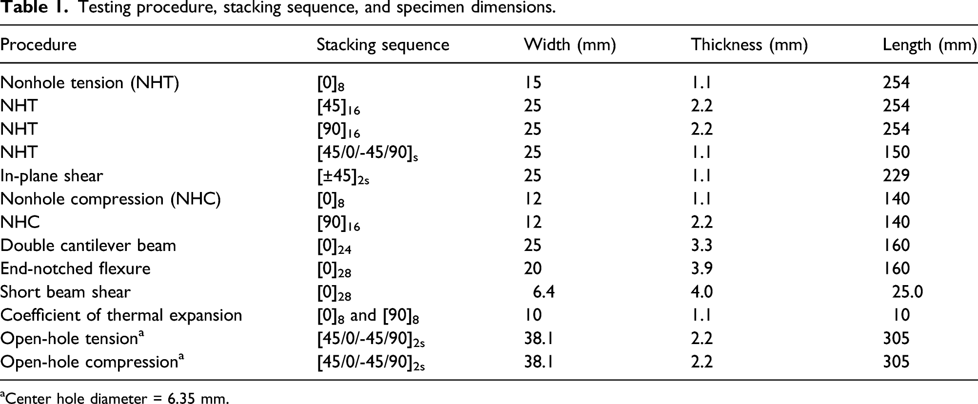
aCenter hole diameter = 6.35 mm.
Tensile/compressive tests
Because unidirectional composite laminates are transversely isotropic, they are described by five independent elastic constants, specifically, three Young’s moduli (E11, E22, and G12) and two Poisson’s ratios (ν12 and ν23). Specimens with longitudinal fiber orientations (i.e., 0°) were prepared to obtain the longitudinal tensile and compressive moduli E11+ and E11–, respectively; in-plane Poisson’s ratio ν12 (=ν13); and longitudinal tensile and compressive strengths XT and XC, respectively. Further, specimens with transverse fiber orientations (i.e., 90°) were prepared to obtain the transversal modulus E22 (=E33) and transversal tensile and compressive strengths YT and YC, respectively. Finally, IPS specimens with fibers at a ±45° angle were used to obtain the in-plane shear modulus G12 (=G13) and shear strength S12. The out-of-plane Poisson’s ratio was assumed to be ν23 = 0.4, and the out-of-plane shear modulus G23 was calculated from E22/2(1 + ν23).
The tensile and compressive stress-strain measurements were performed using an Instron 5985 testing machine with a loading cell of 250 kN. Strain gauges (Kyowa Electronic Instruments Co., Ltd., Japan) were attached to the specimen. To avoid premature failure during the tensile and compressive tests for 0°, 45° and 90° specimens, glass-fiber-reinforced polymer tabs were adhered to both ends of the test specimens using an adhesive film. A displacement rate of 1 mm/min was set, and the specimens were tested until ultimate failure. Both tensile and compressive tests were conducted at least five times for each specimen, including hot-pressed and autoclaved specimens. Young’s modulus was calculated from the slope of the stress-strain diagram with a strain of 0.1–0.3% for NHT, NHC, OHT, and OHC tests and 0.05–0.3% for IPS tests.
DCB/ENF tests
For DCB and ENF specimens, a mold-release-treated polyimide film with a thickness of 12.5 μm was inserted in each composite plate to create the initial precrack (=51.5 and 45.0 mm for DCB and ENF tests, respectively). Then, the specimens were cut from each composite plate by using a diamond saw. For DCB tests, loading blocks were attached to the substrates using an epoxy adhesive (Bond E Set; Konishi Co., Ltd, Japan). The adhesive was cured at room temperature for 24 h.
The DCB and ENF tests were performed at room temperature using an Instron 5967 testing machine with a load cell of 5 kN. In the DCB and ENF tests, a loading displacement rate of 0.1–0.5 and 0.5 mm/min, respectively, was applied, and the load–displacement (P–δ) curve was obtained in each test. Both tests were repeated on at least three samples to obtain the statistical distribution of the measured properties. In the DCB tests, a digital microscope was set up to observe the crack propagation; when the crack tip propagated to the position marked in advance, the corresponding load and elongation were read out. The fracture toughnesses GIc for delamination initiation and GIR for crack propagation were determined by the modified beam theory 24 according to ASTM D5528. The ENF tests consist of applying a three-point bending load to a specimen with a precrack located at its end. Shear loading developed at the crack tip, allowing fracture characterization under mode II loading.
SBS tests
To obtain the Mode II traction (tIIC), the interfacial shear strength was measured by the three-point bending method under ambient conditions, in which the stacking sequence and size of test specimens were [0]28 and 6.4 mm (width) × 4.0 mm (thickness) × 25.0 mm (length), respectively. The span length and crosshead speed for the strength tests were 16.0 mm and 0.05 mm/min, respectively.
OHT/OHC tests
The open-hole samples were tested in an Instron 5985 tensile testing machine with a 250 kN loading cell in accordance with SACMA standard (SRM 3R-94 and 5R-94). The stacking sequence was [45/0/‐45/90]2s (quasi-isotropic laminate), and the dimensions were 305 mm (length), 38.1 mm (width), and 6.35 mm (center hole diameter). The crosshead speed was 1 mm/min, and the stress in the loading direction was obtained by dividing the applied load by the initial cross-sectional area of the specimen. The strain was measured using strain gauges attached at a distance of 25.4 mm from the center of the hole. During the OHT and OHC tests, in situ high-speed digital microscopy (VHX-5000, VH-Z35, KEYENCE Corp.) observations on the transverse hole surface were performed.
Numerical simulation
DCB and ENF analysis
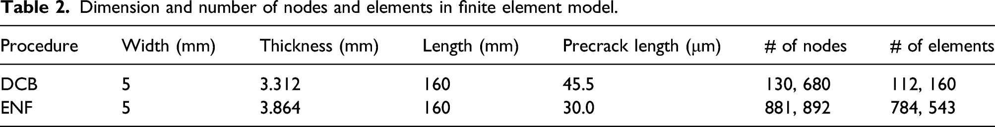
Dimension and number of nodes and elements in finite element model.
OHT and OHC analysis
The quasi-3D XFEM was used to simulate the OHT and OHC strength of CFRTPs. The simulation scheme used in this study was based on a previous study on OHT and OHC simulations of CFRP with CF/epoxy.12,13 Based on the experimental observation, the models for plastic deformation, delamination, multiple intralaminar cracks, fiber breakage, and kink-band failure were taken into consideration. The geometrical nonlinearity was neglected because the observed out-of-plane deformations before the peak load were small in the layup.
The half-thickness of the laminate was modelled assuming a symmetric layup. First, the 3D model with six-node pentahedral elements was made by extruding the two-dimensional triangle mesh data and the potential crack paths for each ply into the thickness direction. Note that all crack paths are preinserted where cracks are expected to occur in each ply based on the knowledge of thermoset CFRP.13,25 The dimensions of the specimen are length L = 205.0 and 101.8 mm for OHT and OHC, respectively, thickness h = 2.21 mm, and width w = 38.1 mm in the numerical models. For both OHT and OHC, a center hole of diameter d = 6.35 mm is modelled. The stacking sequence of the simulation model is [45/0/-45/90]2S. Figure 1 shows the simulation models with preinserted crack paths for both OHT and OHC. Thermal analysis was performed to take into account the thermal residual stress and run the loading analysis. The loading simulation employs an implicit/static solver because the crosshead speed is sufficiently low to be treated as quasistatic. Top view of XFEM simulation models with preinserted crack paths for (a) Open-hole tension and (b) Open-hole compression simulation.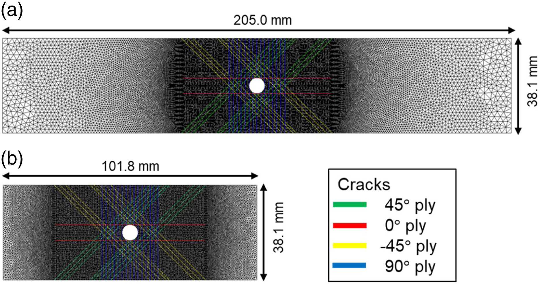
In general, the hydrostatic pressure increases the yield stress and delays crack (delamination) initiation in CFRPs. This study separately models the pressure dependence of the elastoplastic behavior and cracking in CFRTPs. The former is modeled by the pressure-dependent plasticity model proposed by Yokozeki et al. 30 based on the one-parameter plasticity model proposed by Sun and Chen. 31 This elastoplastic behavior model always holds even after the crack initiates because the region around the crack can be elastic or plastic depending on the opening and closing of the crack. The parameters for the plasticity model were determined based on NHT data for 45° and 90° specimens. More details are presented in Elastoplastic behavior.
The pressure dependence of cracking was modeled using the CZM with an enhancement approach proposed by Li et al. 32 The model is based on the Mohr-Coulomb model, and it takes into account the increase in shear strength under out-of-plane compressive stress. The CZM for delamination was introduced by interface elements, 26 and that for intralaminar cracks was introduced by quasi-3D XFEM. 33 In the elements containing crack lines, discontinuity functions were enriched at the nodes to reproduce the discontinuity in the displacement field. Furthermore, these crack elements were divided into several subdomains and one interface element for numerical integration. A plasticity and kink-band models were introduced at integration points in the subdomain, and CZM was implemented at the interface between them. This method allows mesh-independent modeling for multiple cracks in each ply by considering the interaction between each damage mode.
A global fiber tensile failure criterion based on a Weibull statistical model proposed by Hallett et al. 25 was used to predict the OHT strength. Carbon fibers are typically brittle, and their strength decreases with increasing fiber length as explained by the weakest-link theory. Thus, the longitudinal strength of a unidirectional ply consisting of brittle fibers can likely also be characterized by a Weibull statistical model. In this study, the fracture propagation law was not introduced because the tensile fracture in the fiber direction in a certain region will cause the fracture to propagate to the whole region immediately, and the critical fracture was assumed to occur when the Weibull fracture criterion was satisfied.
For kinking initiation in OHC, the LaRC03 fracture criterion 34 with simplifications proposed by Maimí et al. 35 was used. Here, kinking is assumed to be caused by the initiation of damage in the supporting matrix. After damage to the support matrix, the fibers lose their lateral support and fracture under longitudinal compressive stress, corresponding to the beginning of kinking. After kinking initiation, the kink-band propagation was modeled by the smeared crack model (SCM) 36 to capture the energy dissipation during kink-band formation. In the softening region, the zig-zag softening law 37 was introduced because of its superior convergence in iterative calculations. The OHC analysis was terminated when the compressive stress decreased by 5% relative to the maximum value. The detailed formulations of the quasi-3D XFEM12,33 and the descriptions of the CZM for delamination, 38 Weibull criterion, 25 and LaRC03 failure criterion 34 can be referred elsewhere.
Results and discussion
Uniaxial tensile/compressive tests and SBS tests
Comparison of material properties of T700G/LM-PAEK obtained in this study with those of thermoset carbon-fiber-reinforced plastics.
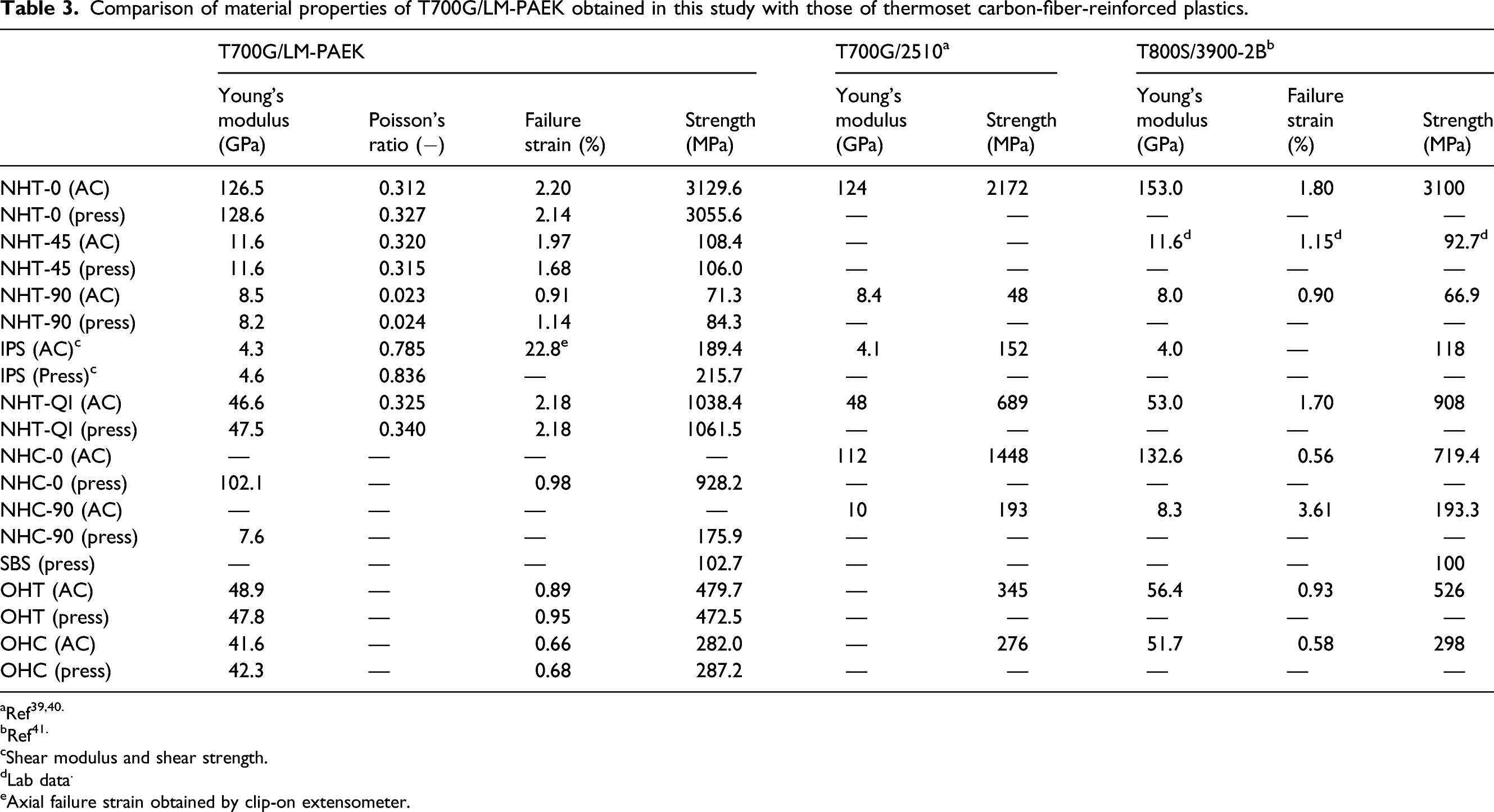
bRef41.
cShear modulus and shear strength.
dLab data.
eAxial failure strain obtained by clip-on extensometer.
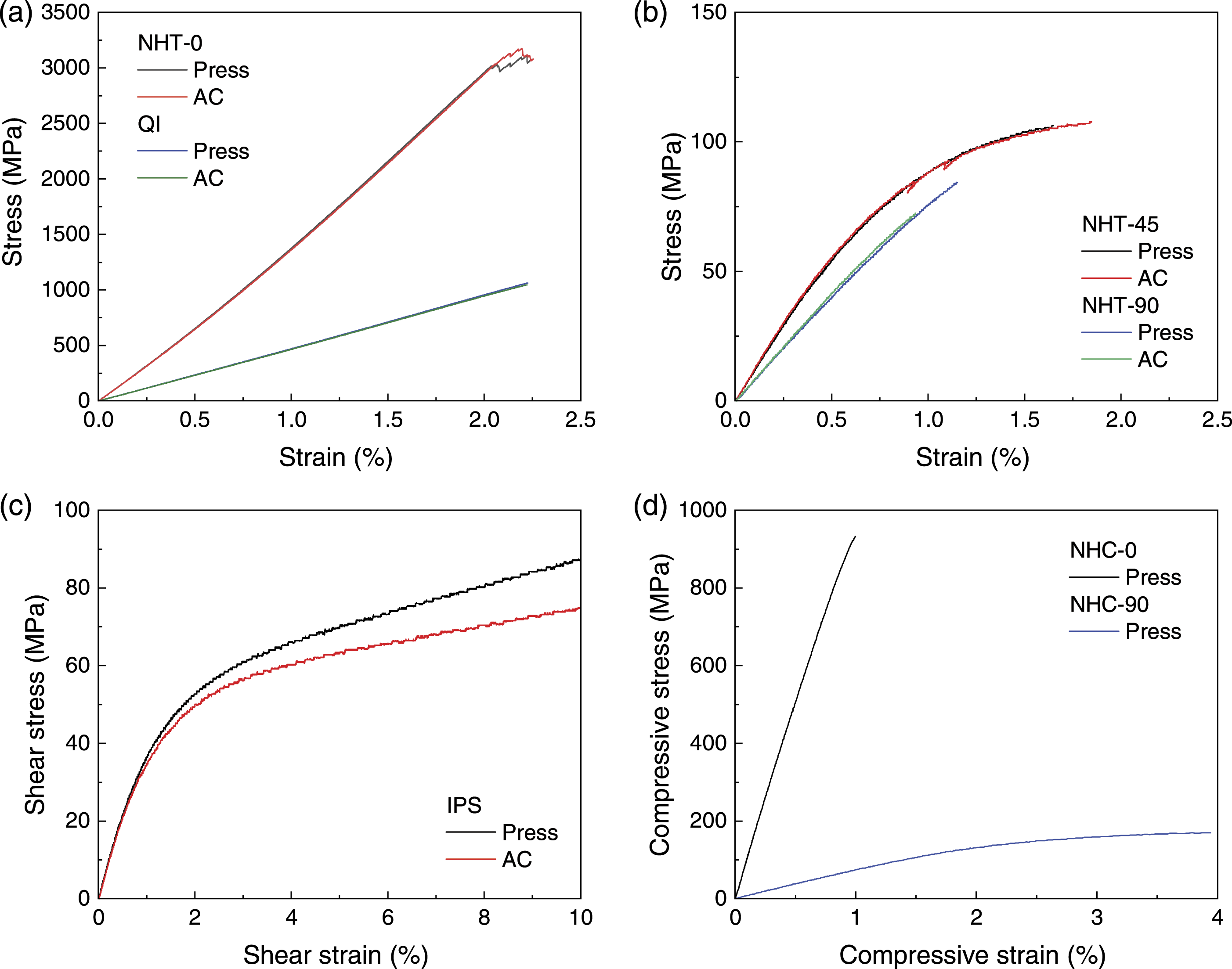
Stress-strain curves for uniaxial tensile and compressive tests: (a) NHT-0 and quasi-isotropic (NHT-QI) specimens, (b) NHT-45 and NHT-90 specimens, (c) IPS specimens, and (d) NHC-0 and NHC-90 specimens.
Elastoplastic behavior
CFRPs exhibit very complex nonlinear behavior, including plastic deformation of the matrix, microcracks, fiber rotation, and geometric nonlinearity. In particular, as mentioned above, nonlinear material behaviors occurring before crack onset cannot be ignored in CFRTP. Yokozeki et al.
30
proposed an anisotropic pressure-dependent elastoplastic constitutive law based on the one-parameter plasticity model proposed by Sun and Chen
31
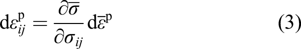
to take into account the unique nature of CFRP, in that it exhibits different nonlinear responses under tensile and compressive conditions. We used this model to predict the nonlinearity of CFRTPs. The simulation procedure is explained only briefly below; the detailed theoretical model can be referred elsewhere.12,30 First, the following decomposition of the total strain increment 
Note that the local system of a single lamina is represented with i = 1, 2, 3 and j = 1, 2, 3, where 1, 2, and 3 respectively denote the fiber direction, in-plane transverse to the fiber direction, and out-of-plane transverse to the fiber direction. The incremental form of the elastic constitutive law is written as
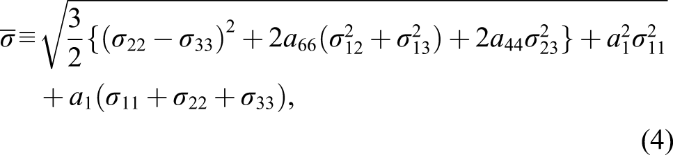
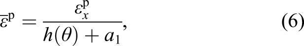
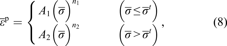
Next, the procedure to determine the material parameters30,31 is discussed. The effective stress 
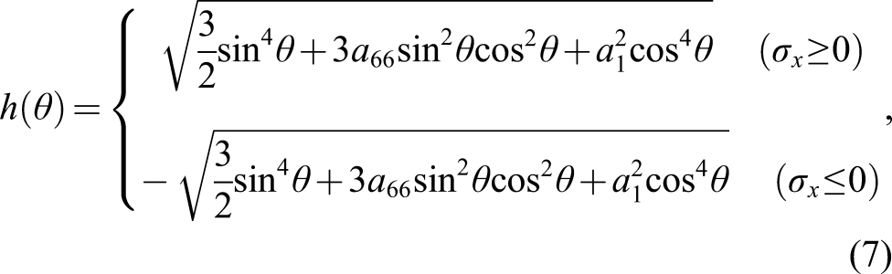
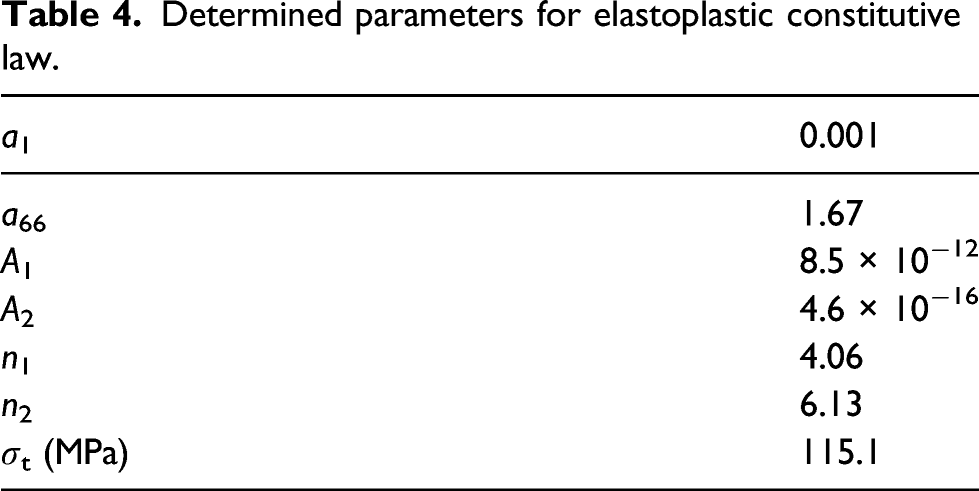
Determined parameters for elastoplastic constitutive law.
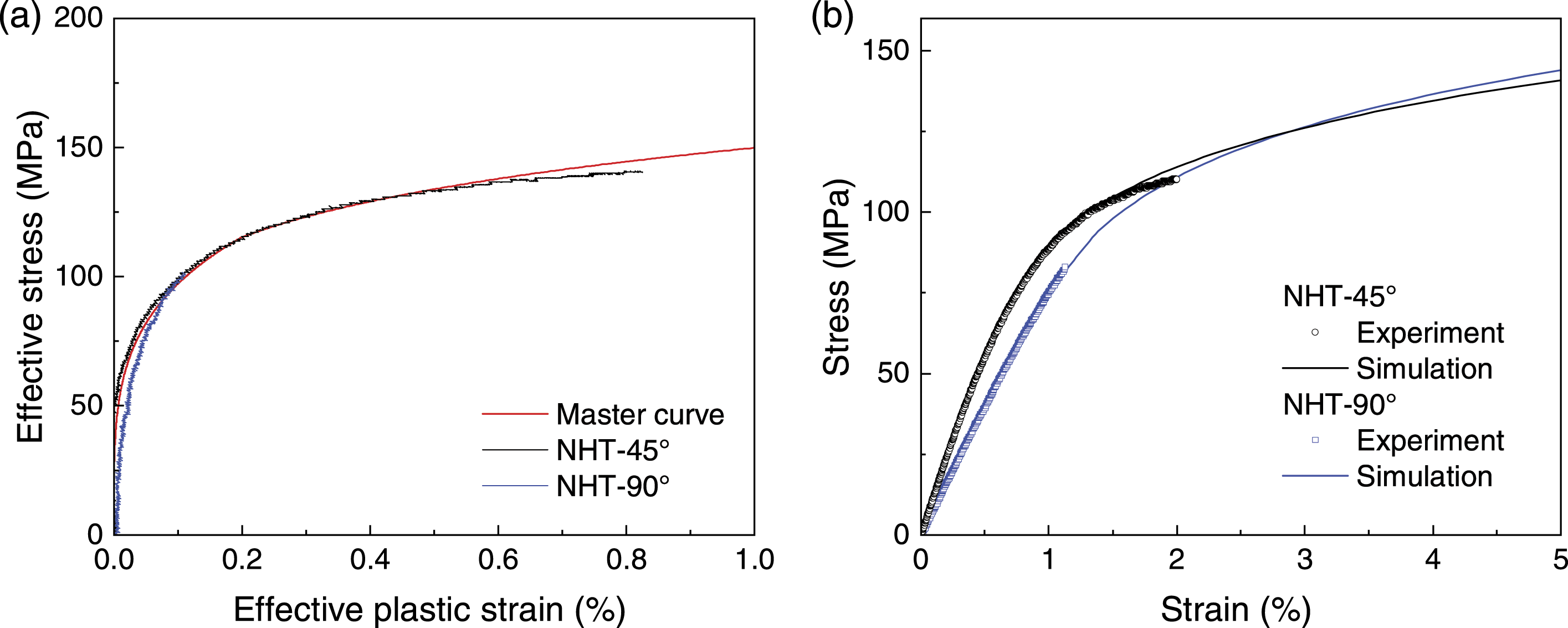
(a) Master curve of effective stress–effective plastic strain relation. (b) Comparisons of experimental and predicted stress–strain curves for nonhole tension 45° and 90° specimens.
Interlaminar fracture toughness
The mode I and mode II interlaminar fracture toughnesses (GIc and GIIc) of CFRPs are critical parameters in evaluating the integrity and damage tolerance of laminated composite structures. However, few studies have measured the interlaminar fracture toughness of CFRTPs. In this study, to simulate the interlaminar delamination and intralaminar cracks by CZM and quasi-3D XFEM, the mode I and mode II interlaminar fracture toughnesses were evaluated through DCB and ENF tests and simulations.
Figure 4(a) shows typical experimental load-displacement curves of the T700G/LM-PAEK specimens during DCB tests. In the nonprecrack test (initial loading, black solid line in Figure 4(a)), the load increased linearly, and the specimen was unloaded after the crack was observed to propagate from the inserted film tip (specimens are not precracked before testing). The interlaminar fracture toughness for delamination initiation (GIc) at which delamination was visually observed to propagate from the inserted film tip (approximately 9 mm in displacement) was determined, and it was calculated to be 1.50 ± 0.15 N/mm based on the modified beam theory.
24
This value is approximately three times larger than that of the thermoset CFRP (T800S/3900-2B, 0.54 N/mm41). After unloading, the specimen was reloaded at the same crosshead speed as in nonprecrack testing until the final delamination length increment was reached. When the tensile load reached a critical value, it gradually decreased with delamination crack propagation. Figure 4(b) shows the mode I interlaminar fracture toughness for crack growth (R-curves). The GI values increased rapidly with increasing delamination length after initiation and reached around 2.27–2.49 (mean 2.35) N/mm, corresponding to GIR. This value is close to that of polyamide-based CFRTPs (=2.0–2.4 N/mm5). Extensive fiber bridging was observed during delamination growth; it contributed to the high GIR value compared with the GIc value. (a) Experimental and numerical load-displacement curves and (b) experimental R-curve of the DCB tests.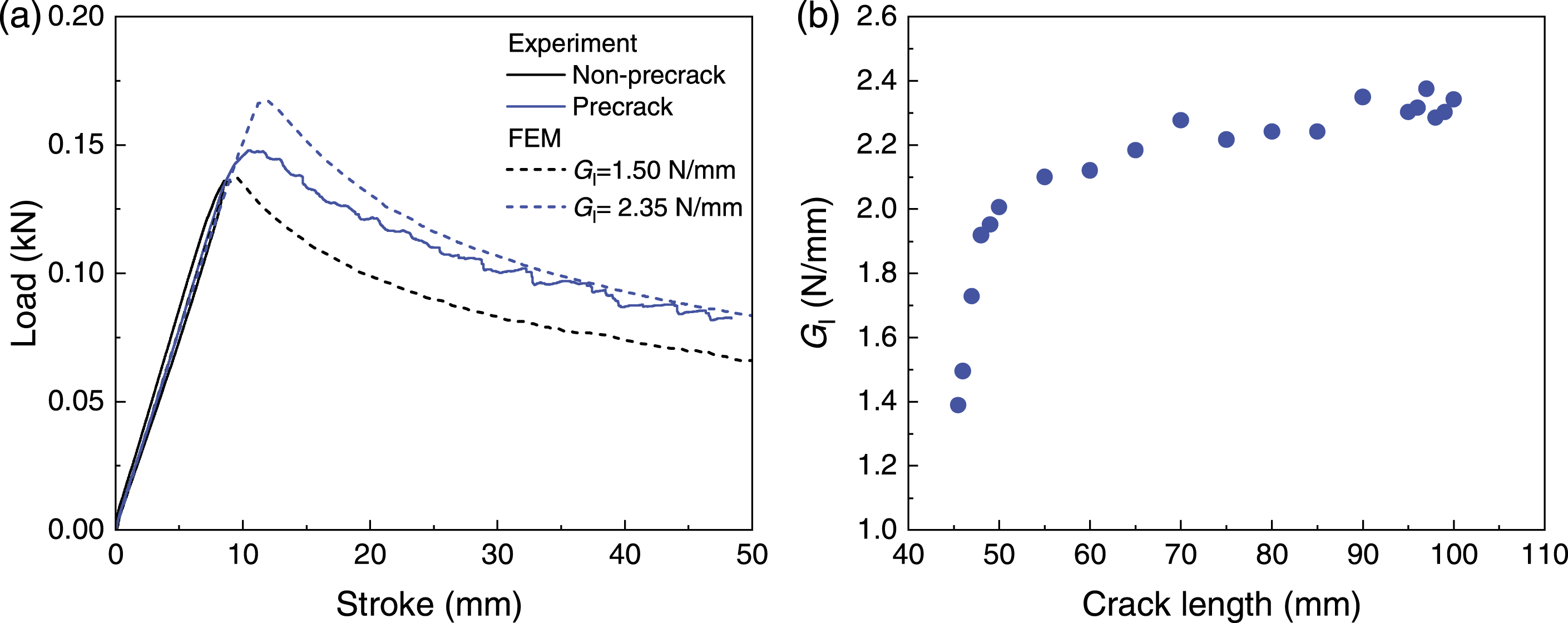
Material properties used in finite element analysis.
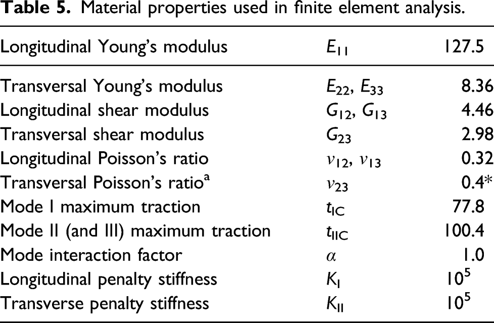
Figure 5 shows typical load-displacement curves of ENF tests for the T700G/LM-PAEK specimens. For each specimen, the load increases linearly, and subsequently, load drop occurs owing to crack propagation. The mode-II fracture toughness (GIIc) calculated by the compliance calibration method
46
is in the range of 2.18–2.55 (mean 2.35) N/mm, that is, it is approximately 1.4 times larger than that of thermoset CFRP (T800S/3900-2B, 1.64 N/mm41). Because crack growth was not observed with a microscope in the ENF test, a parametric study was performed to numerically determine the mode II interlaminar fracture toughness for crack growth (GIIR) by using the experimental results. The black dashed line in Figure 5 indicates the numerical result obtained with the experimental GIIc (=2.35 N/mm), where the mode II traction (tIIc = 100.4 MPa) is determined by the SBS tests as shown in Table 3. The displacement at which the peak load drops is smaller than that at the experimental peak load, suggesting that delamination occurs before the experimental peak load and GIIR increases during crack propagation. When GII is set to 2.7–3.2 N/mm, the numerical result agrees reasonably well with the experimental one, corresponding to the plateau region of the R-curve. Experimental force-displacement curves obtained from end-notched flexure tests, along with the numerically predicted force-displacement curves with the mode II fracture toughness for crack initiation (GIIc) and upper and lower limits of mode II fracture toughness for crack propagation (GIIR).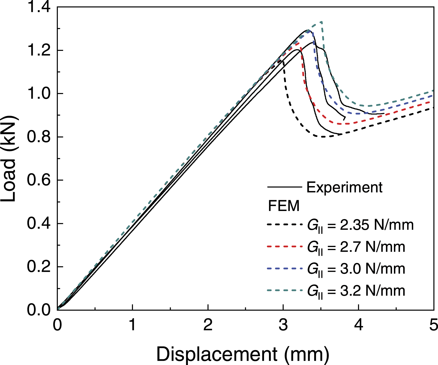
Finally, we discuss whether the interlaminar fracture toughness value used in the XFEM analysis for OHT/OHC tests should be the value at crack initiation (GIc and GIIc) or at crack propagation (GIR and GIIR). Fiber bridging47,48 is unlikely to occur between the plys of the OHT/OHC model because these plys have different stacking angles; therefore, GIc and GIIc are considered suitable for the interface elements between the plys. By contrast, because the crack surface corresponding to splitting and transverse cracks is also expected to exhibit fiber bridging between plys with the same stacking angle (0°/0°), GIR and GIIR are expected to be appropriate for the interface elements of the crack surface.
Overall, the appropriate values of each CZM parameter, such as the tractions (tIc and tIIc) and interfacial fracture toughnesses (GIc, GIR, GIIc, and GIIR) of T700G/LM-PAEK are clarified. These should be helpful for predicting the mechanical properties of T700G/LM-PAEK by XFEM, as described in Open-hole tension and Open-hole compression.
Open-hole tension
Laminate properties used in extended finite element method.
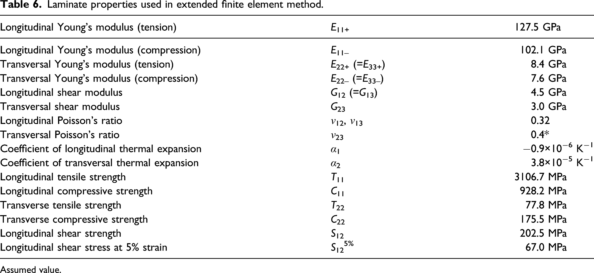
Assumed value.
Interlaminar properties used in extended finite element method.
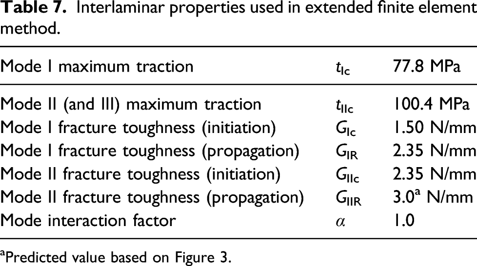
aPredicted value based on Figure 3.
Figure 6 shows the experimental and computational stress-strain diagrams for OHT tests. To compare the stress-strain diagrams obtained through the analysis and the experiment, the strain was calculated from the displacement of the nodes at a distance of 25.4 mm from the center of the hole. The experimental results (black and gray solid lines) reveal an approximately linear elastic regime up to the point of fracture strength of 472–479 MPa at a strain of 0.89–0.95 (Table 3). As described below, fiber breakage is the main failure mode in OHT as characterized by the Weibull statistical model, and the Weibull modulus (m) is set to 41. The computational model (red broken line in Figure 6) provides an accurate prediction of the stress-strain response, that is, plastic deformation occurs at a strain of 0.6% and the failure strength agrees well with the experimental value. Experimental and numerical stress-strain curves for Open-hole tension tests.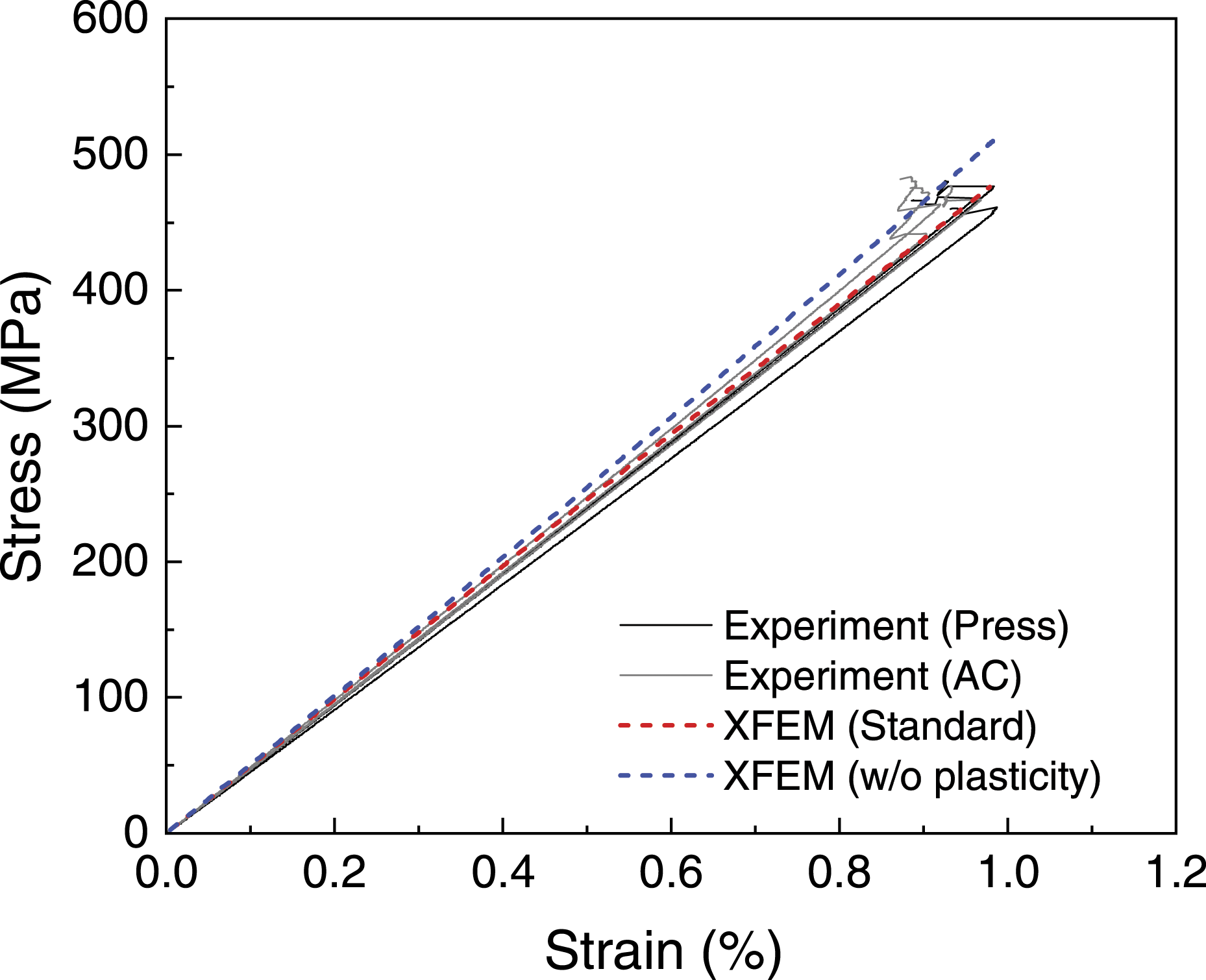
Figures 7(a)–(c) show the in-situ damage observation results before the fracture of the OHT specimen and the damage near the hole after fracture. The initial damage detected by the high-speed digital microscope occurred in the 45° ply just before the peak load. Because the OHT specimens exhibited brittle fracture after reaching the peak load, the fiber breakage in the 0° ply is considered the main failure mode. The damage in the 0° ply propagated in the 45° or 90° direction near the hole and in the −45° direction away from the hole. Thus, the initial crack in the 45° ply was concluded to cause the damage in the 0° ply, which then propagated in the specimen width direction while interacting with the crack in the −45° ply. Figure 7(d) shows the predicted internal damage distributions just before the judgement of failure, where the amount of crack propagation is small, and crack initiation points exist only in the 45° and −45° plies. At the failure strain, the Weibull criterion was satisfied without any delamination; this agrees reasonably well with the experimental observation. In-situ microscope observation results at (a) 99.7% of peak load and (b) 100% of peak load and (c) fracture surface after the OHT tests. Predicted damage distributions after fracture: (d) standard model and (e) model without plasticity.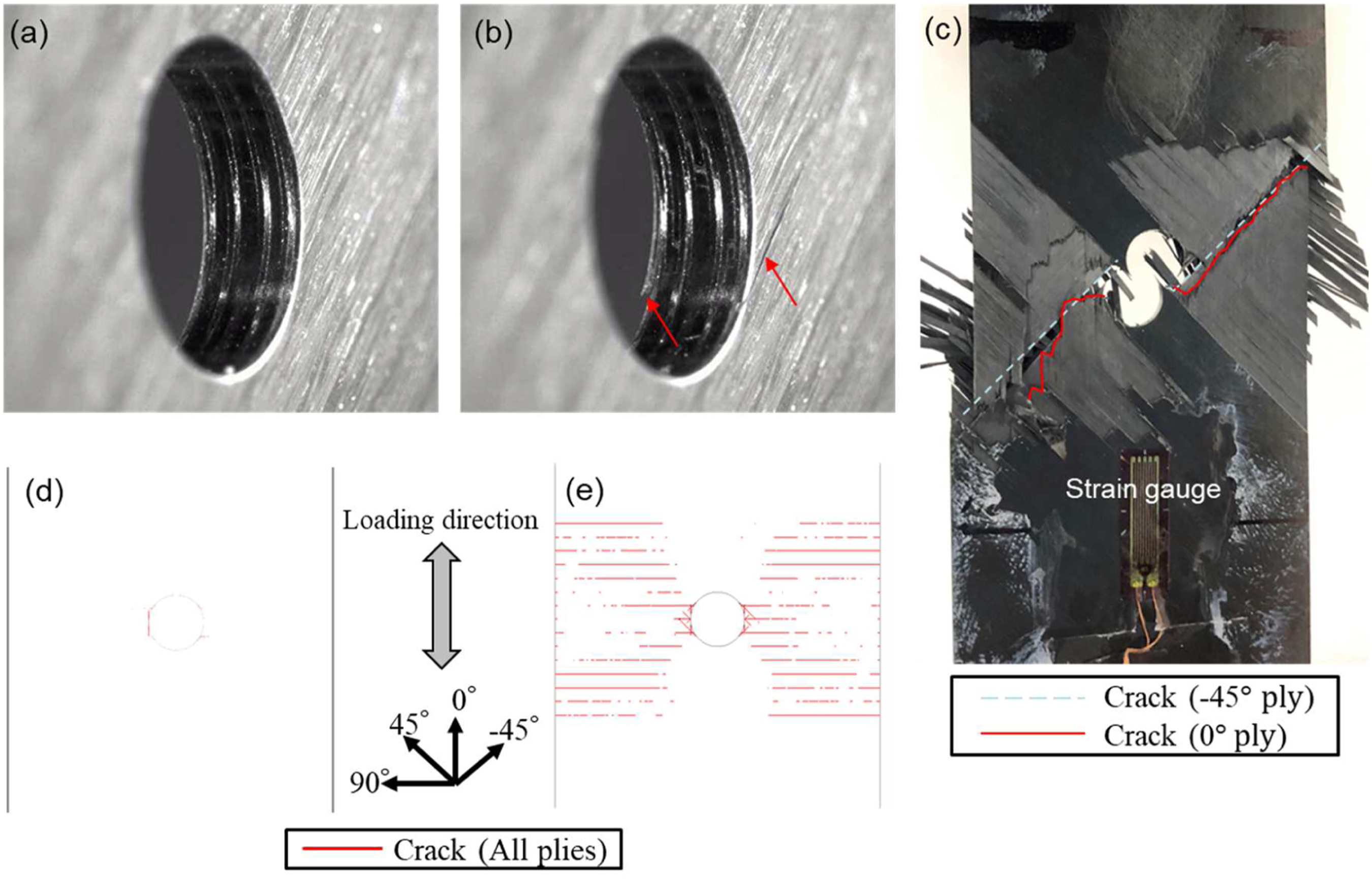
The blue dashed line in Figure 6 indicates the linear stress-strain curve through XFEM calculations without the elastoplastic constitutive law, which overestimates after the strain exceeds 0.6%. This suggests that the influence of plastic deformation of the thermoplastic resin is likely to be evident in this strain range. Additionally, when plastic deformation is not considered, strain energy is consumed for damage generation and not for plastic deformation, resulting in a larger amount of damage propagation as shown in Figure 7(e). Therefore, we conclude that it is necessary to consider the plastic deformation in the numerical analysis of CFRTPs.
Open-hole compression
Figure 8 shows the experimental and numerical stress-strain curves obtained from OHC tests. Further, Tables 6 and 7 list the material properties of T700G/LM-PAEK used in XFEM for OHC simulations. The LaRC03 criterion assumes that kinking is triggered by the onset of damage in the matrix, and the damage initiation of the matrix depends on the in-plane longitudinal shear strength S12,13 the value of which is 118 and 92.3 MPa in T800S/3900-2B and IM7/8552 CFRTPs, respectively.17,41 By contrast, for T700G/LM-PAEK used in this study, the stress value at 5% strain S125% (67.0 MPa) was used as the S12 value instead of the shear stress at failure (185–211 MPa). This is because the axial failure strain is too large (∼23% as measured by the clip-on extensometer) to use as the parameter to describe the onset of damage in the matrix for OHC simulation. The ASTM standard also states that if ultimate failure does not occur within 5% shear strain, the 5% shear strain point should be considered the maximum shear stress.
49
The experimental stress-strain response increased linearly up to a strain of 0.4%. The stress continued to increase approximately linearly until failure beyond a strain of 0.4%, although the slope of the stress-strain curve decreased slightly. A comparison between the stress-strain curves obtained through experiments and simulations (red broken line) indicated that the stress-strain response was accurately captured using the computational model when the critical energy release rate for kink-band propagation (Gkink) was set to be 36 N/mm. Experimental and numerical stress-strain curves for open-hole compression tests.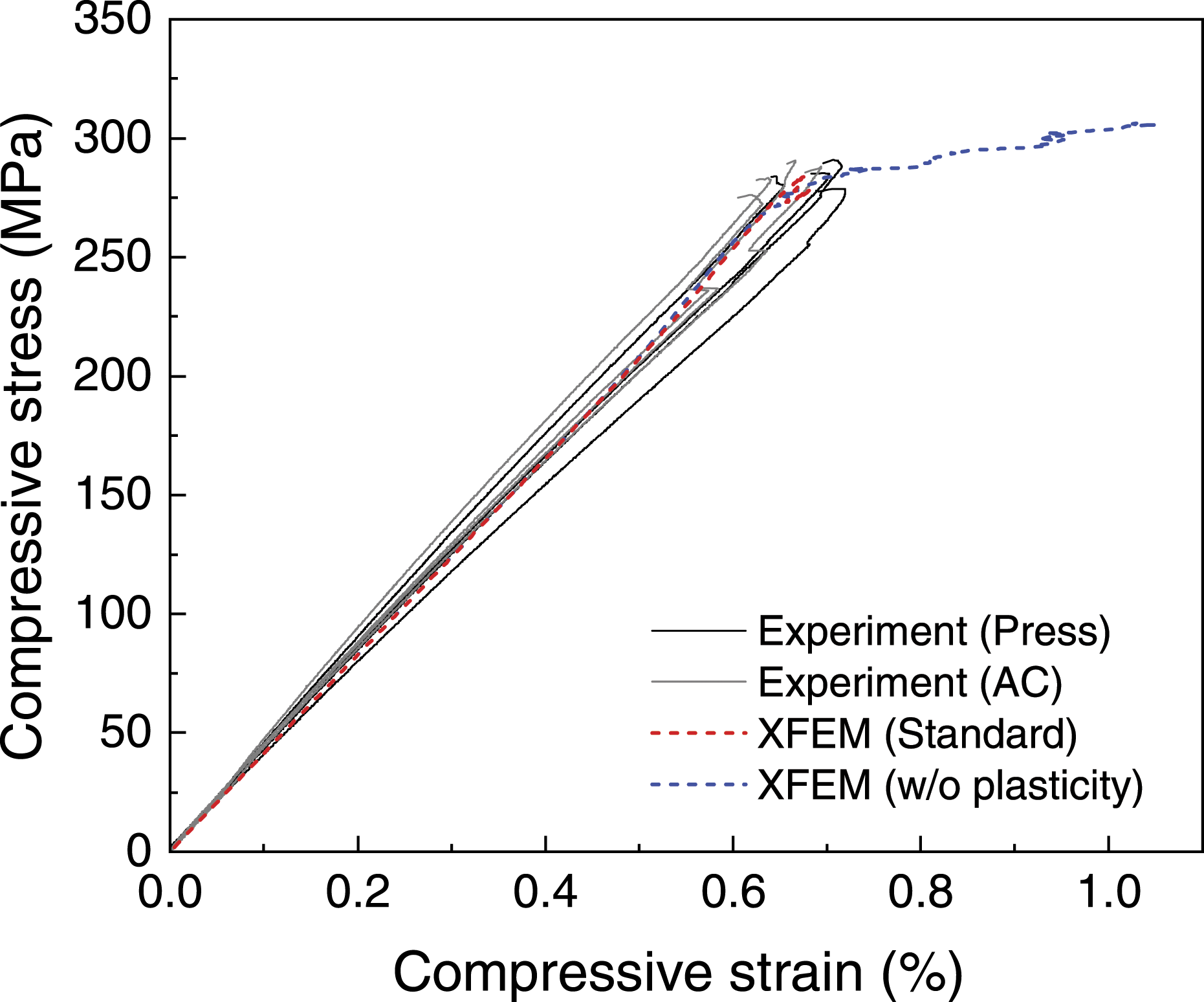
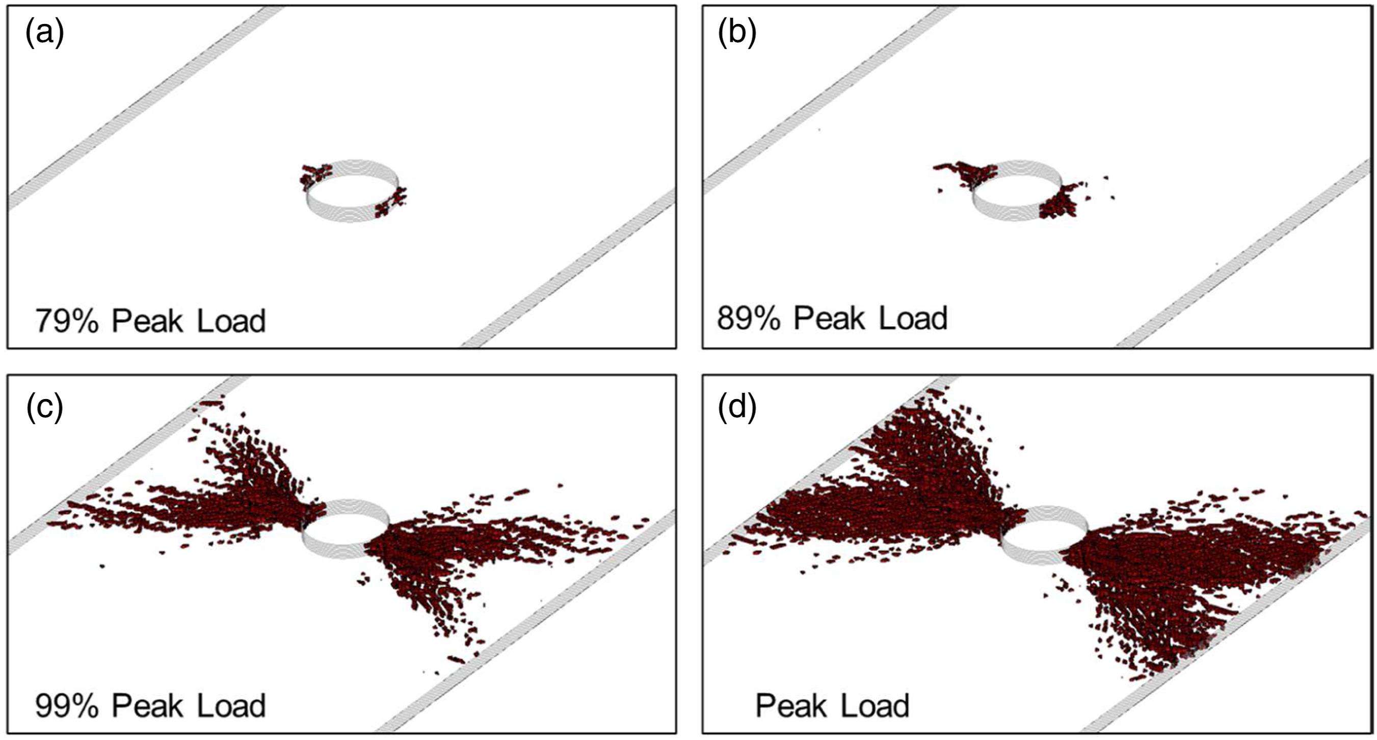
Figure 9(a)–(d) summarize the in-situ damage observation results before damage initiation at 88%, 90%, and 100% of the peak stresses. The initial damage detected by a high-speed digital microscope was observed in 0° ply at 88% of the peak stress (Figure 9(a)), corresponding to the 0°-ply kinking. Subsequently, similar damage was observed near the other 0° plys with fracture noise (Figure 9(b)), and the damage was observed to develop in the width direction just before fracture (Figures 9(c) and (d)). Figure 9(e) shows the damage near the hole after the experimentally obtained fracture, where the damage propagates in the direction of approximately −60°. Figure 10 shows the numerical damage distributions. Damage initiation was observed in the 0° plies and its nearby plys at 87% of the peak stress, which is close to the experimental values, and the direction of damage propagation at final failure was consistent with the experimental results. In-situ high-speed digital microscope observation results at (a) 88%, (b) 90%, (c) 99%, and (d) 100% of the peak load. (e) Damage near the hole after the open-hole compression test. Predicted damage distributions at (a) 79%, (b) 89%, (c) 99%, and (d) 100% of the peak load. Damage initiates from around the 0° ply and propagates in the direction of approximately ±60°.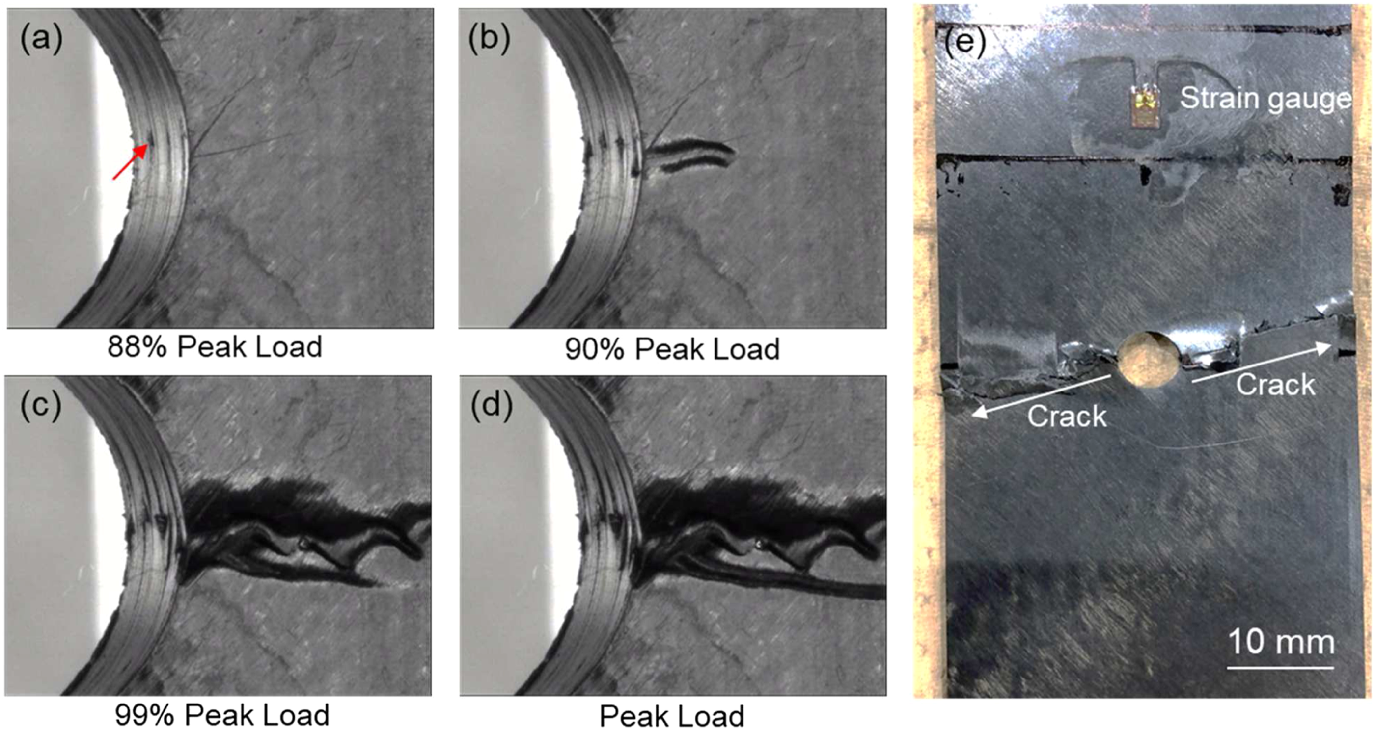
The blue dashed line in Figure 8 represents the XFEM calculations without the elastoplastic constitutive law. There is little difference between the standard model and the model without the elastoplastic constitutive law up to the peak stress of the standard model, in keeping with a previous study of thermoset CFRP. 13 However, in the model without the elastoplastic constitutive law, the compressive stress continued to increase with damage, and no load drop was observed even when the same compressive displacement as in the standard model was applied. The increase in compressive strain may be due to the deformation of elements far from the hole owing to damage. In this study, the kink-band propagation was modeled by the SCM, and kink-band propagation was difficult to observe in the model without plasticity mainly owing to the large critical energy release rate for kink-band propagation (Gkink). Higuchi et al. 13 experimentally and analytically evaluated the OHC properties of thermoset CFRP with different lamination configurations and demonstrated that neglecting the plasticity can cause premature shear cracking and resultant final failure in the layup containing the smaller 0° ply ratio. Because the CFRTP used in this study exhibits large material nonlinearity, the effect of the different lamination configurations on the OHC properties is expected to be more pronounced in CFRTP.
Overall, the predicted stress–strain response, fracture strength, and damage scenario and distributions for OHT and OHC are reasonably consistent with the experiment, and we conclude that the analytical model used in this study can simulate the stress-strain response and damage behavior of CFRTP to OHT and OHC.
Conclusions
This study experimentally and numerically elucidated the strength and damage initiation/propagation mechanisms of T700G/LM-PAEK, a CFRTP, through OHT and OHC tests and quasi-3D XFEM analysis. Material properties including Young’s modulus, Poisson’s ratio, tensile/compressive strength, CTE, and interlaminar fracture toughness were obtained experimentally to compare the differences in mechanical properties between thermoset CFRPs and to analyze OHT and OHC properties by XFEM. Uniaxial tensile/compressive tests showed that T700G/LM-PAEK had similar or better properties than the thermoset CFRPs T700G/2510 and T800S/3900-2B. Additionally, DCB and ENF tests showed that T700G/LM-PAEK had higher mode I and mode II interlaminar fracture toughnesses than thermoset CFRPs. These superior mechanical properties are mainly attributable to the higher toughness and ductility of the thermoplastic resin of LM-PAEK. By determining the mode I and mode II tractions from the tensile strength of the 90° specimen and the interlaminar shear strength obtained from the SBS test, respectively, the mode I and mode II interfacial fracture toughnesses for crack initiation and propagation were evaluated by FEA with CZM to determine the CZM parameters for delamination and intralaminar cracks used in XFEM for OHT/OHC simulations.
Based on the above experimental and numerical results, the stress strain response and damage evolution of the open-hole specimens were analyzed by XFEM and compared with the experimental results. For the OHT tests, the initial crack in the 45° ply led to the damage in the 0° ply, and the specimen exhibited brittle fracture after reaching the peak load, suggesting that the fiber breakage in the 0° ply is the main failure mode. The numerical analysis also demonstrated that crack initiation points exist in only the 45° and −45° plies. At the failure strain, the Weibull criterion was satisfied without any delamination; this was in reasonable agreement with the experimental observation. The in-situ damage observation during OHC tests revealed the results before damage initiation and at 88%, 90%, and 100% of the peak stress. The initial damage was observed in the 0° ply at 88% of the peak stress, corresponding to the 0°-ply kinking. Subsequently, damage was observed to develop in the width direction just before fracture. This damage initiation and propagation was also predicted by XFEM. A comparison of the experimental and numerical stress-strain curves of both OHT and OHC indicated that the computational model with the elastoplastic constitutive law provided an accurate prediction of the stress-strain response, suggesting that the elastoplastic constitutive law should be considered in XFEM to guarantee the accuracy of strength prediction for both OHT and OHC.
Footnotes
Declaration of conflicting interests
The author(s) declared no potential conflicts of interest with respect to the research, authorship, and/or publication of this article.
Funding
The author(s) disclosed receipt of the following financial support for the research, authorship, and/or publication of this article: This paper is based on results obtained from the JPNP20010 project commissioned by the New Energy and Industrial Technology Development Organization (NEDO). This research was also supported by the Council for Science, Technology, and Innovation (CSTI) and the Cross-ministerial Strategic Innovation Promotion Program (SIP), ‘‘Materials Integration for revolutionary design system of structural materials’’ (Funding agency: JST).