
Abstract
A novel intralaminar model has, for the first time, been applied and validated for the rate-dependent failure of multidirectional carbon/epoxy laminates. Quasi-static compressive failure is evaluated by the growth of intralaminar rate-dependent damage combined with the interaction of cohesive zones for interlaminar delamination. A special feature of the intralaminar model is the homogenised ply response, allowing simultaneous damage-degradation of the polymer matrix combined with the fibres. To model the observed quasi-brittle failure response of the plies under finite deformation, we have used a viscoelastic-viscoplastic matrix combined with damage and isotropic hardening behaviour. Elastic transverse isotropy is used to model the fibre reinforcement of the plies. Standard cohesive surfaces are used to model the initiation and propagation of delamination. Numerical simulations using ABAQUS/Explicit are performed to predict the growth and delamination of intralaminar damage under compression in different laminates with 56 plies of IM7/8552 carbon/epoxy. Predictions of stress versus strain and damage growth are shown to agree well with experimental results for a range of strain rates and stacking sequences.
Keywords
Introduction
Due to their high stiffness and strength, laminated composite materials are widely used in modern lightweight structures such as aerospace structures.1,2 In many structural applications, composite materials are exposed to various dynamic loads such as the strike of birds on aerostructures 3 and the crash of large vehicles, 4 producing multiaxial dynamic states of stress. In addition, the strain rate has significant effects on mechanical properties, such as strength and stiffness.5–7 Several authors investigated the effect of strain rates on unidirectional compounds,8–10 as reviewed by Singh 11 and Sierakowski. 12 In order to accurately predict the initiation and propagation of intra- and interlaminar dynamic damage, the establishment of a strain-rate-dependent constitutive model at the ply level of the laminate is crucial. Some models based on phenomenological invariance exist and describe viscoelastic/viscoplastic effects in polymer composites, but without damage growth.13–15 Continuum damage-based models were proposed by,16,17 including fibre kinking theory, for example.18–20 Larsson et al. 21 proposed a micromechanics-based model dependent on the strain rate for unidirectional polymer composites at the ply level. This model was later extended to include the continuum damage formulation 22 and was applied to different material systems 23 to demonstrate the robustness of the model. In the model, the polymer matrix is assumed to be viscoelastic-viscoplastic with damage, whereas the carbon fibres are transversely isotropic elastic.
Fibre reinforced composites usually demonstrate intra- and interlaminar damage modes that develop and interact with each other in a complicated way. To exploit the damage mechanisms of composite materials under dynamic loading, many failure prediction models have been developed, and the progressive damage method and the cohesive zone method have been commonly adopted24,25 to evaluate complicated damage patterns in composite structures. Delamination is commonly considered to be an important failure mechanism of composite laminates with weak interfaces that severely decrease the stiffness and strength of the structures. Delamination problems are often represented by the initiation and propagation of ply separation on the basis of cohesive zone models. In finite element (FE) analysis, this is often achieved through cohesive elements/surfaces.26,27 Cohesive zone models describe the relationship between traction and displacement jump in the cohesive zone ahead of a crack tip. Several shapes have been proposed for the involved traction-separation law, including bilinear, exponential 28 and trapezoidal laws. 29 The objective of this paper is to apply the strain rate-dependent damage model developed in22,23 while including isotropic hardening to realistic multidirectional carbon/epoxy laminates with multiple layers subjected to static and dynamic compressive loading rates. The current model version 23 excludes damage growth in the viscoelastic range, included in, 22 as it was found to result in excessive softening in disagreement with experimental observations for typical epoxy resins. The intralaminar model is combined with a cohesive model to validate the growth of intra- and interlaminar damage. To describe the compressive failure of the composite, two components are proposed: a rate-dependent model for the quasistatic intralaminar response and a surface-based cohesive zone model for characterising the interlaminar delamination. In this paper, a bilinear cohesive law is used. When applied to large structures, the shape of the cohesive law has been shown not to influence the overall response, as long as the area below the traction separation law is equal to the resistance to fracture and the element size is not larger than the process zone. 30 Therefore, for simplicity, the bilinear traction separation laws31,32 are the most commonly used to describe delamination in composite materials. The laminate model is implemented as a material subroutine in the finite element code ABAQUS/Explicit. The proposed model is validated by detailed comparisons between numerical predictions and experimental results for laminates with 56 plies in different layups.
Strain-rate-dependent damage model
To capture the nonlinear dynamic response of a composite structure, a strain-rate-dependent damage prediction model based on the progressive continuum damage and the cohesive law is established. Relevant modelling details are presented in this section. The following sub-sections briefly present the constitutive laws used to describe the behaviour of the fibre and matrix material of the fibre reinforced angle plies.
Constitutive model for carbon fibres
The rectangular RVE used to develop the micromechanical relations is denoted V⊡ as shown in Figure 1(a). The fibre region is indicated by Schematic representation of (a) a representative volume element (RVE) and (b) a rheological model for the rate-dependent effective stress deviator of the polymer matrix.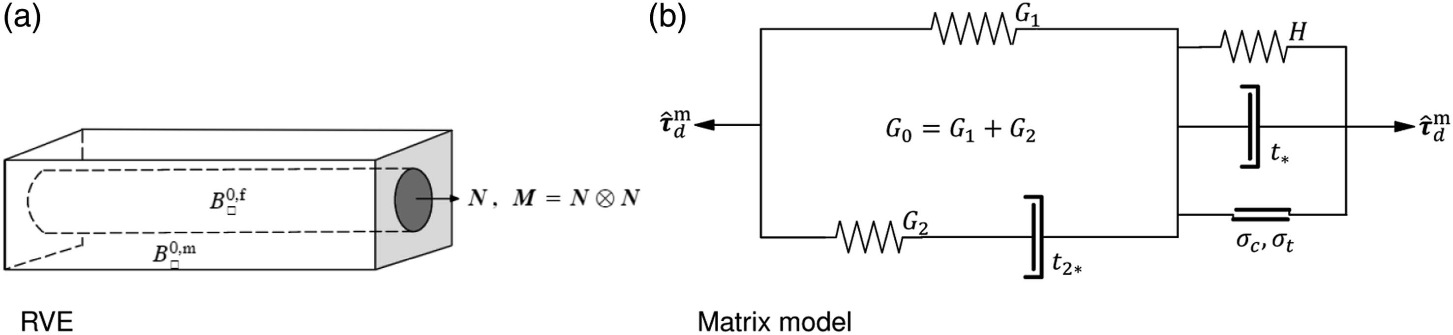
The fibres are considered transversely elastic isotropic, characterised by the strain energy ψf = ψf (

Dynamic model with damage/hardening for polymer matrix
The matrix is assumed viscoelastic-viscoplastic, enhanced by continuum damage to describe the degradation due to shearing in the polymer, as proposed in Ref. 22. In the present paper, the viscoplastic model is extended to include isotropic hardening. Figure 1(b) shows the rheological model for the matrix material. The viscoelastic model is based on a generalised three-parameter Maxwell model defined by quasistatic and dynamic shear moduli G1, G0 (via G2) and a viscoelastic damper with relaxation time t2*. This is coupled to a viscoplastic model defined by a quasistatic pressure-sensitive yield in the polymer (with parameters σ
t
and σ
c
representing uniaxial tension and compression), a viscoplastic relaxation time t* and the constant hardening modulus H. The viscosity parameters act as “delay” parameters, activating the viscoplastic behaviour at “high” stresses. Following,
22
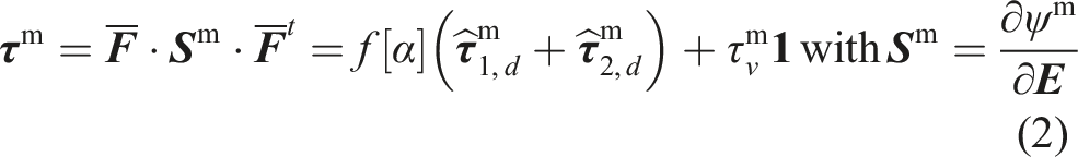
the total Kirchhoff stress in the matrix is obtained as


Evolution rules
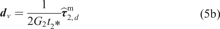
Following the developments in,22,23 the viscoplastic/viscoelastic and hardening rules for the matrix shear response are defined as
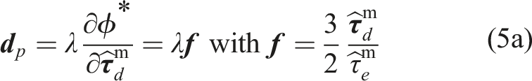

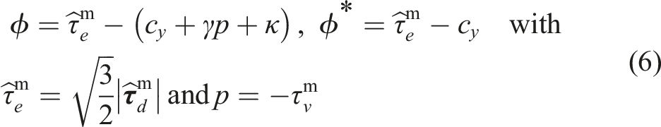
The yield and plastic functions ϕ and ϕ* are defined as
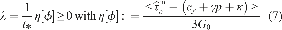
A Perzyna-type Bingham model is adopted for viscoplasticity. λ is the viscoplastic multiplier defined as
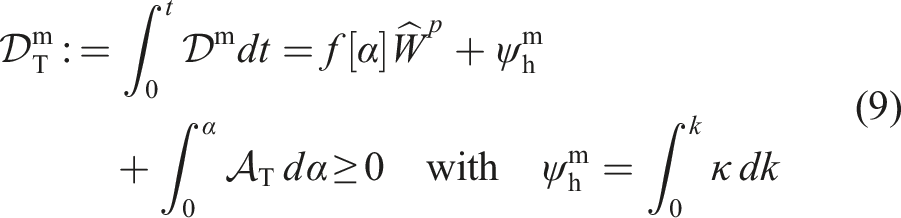
Following,22,23 the progression of α for the damage degradation function f [α] in equation (2) is rate-dependent and is driven by viscoplastic dissipation in the matrix. The damage evolution is defined as
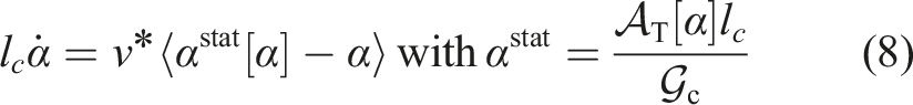
The damage parameters involved are: the fracture energy

Homogenized UD-ply stress response
Following the developments in,22,23 it appears that the homogenized UD-ply stress response is obtained explicitly as


A major feature of homogenisation is that the homogenised response of a unidirectional composite ply assumes isostrain response along the fibres, whereas isostress response is assumed for the transverse normal and in-plane shear directions of the ply. To improve the response of the elastic model, Halpin-Tsai-based predictions for the numerical model are used to consider the nonuniform stress distribution in the matrix. 23 Furthermore, in 23 , the isostress field has been adjusted by separating normal stresses controlled by the parameter a m and shear stresses controlled by the parameter b m .
Interlaminar traction-separation model
To capture the delamination of the ply to the ply under dynamic loading conditions, the standard surface-based cohesive zone method in Abaqus is used. Surface-based cohesive behaviour is chosen primarily because the interface thickness is negligible compared to the thickness of the ply. Thus, a cohesive zone model is used to degrade the traction vector of the interlaminar interface. The model consists of a traction-stick-separation law. An elastic penalty is used to handle the stick case, while a stress-based delamination initiation criterion is used along with a fracture mechanics-based delamination propagation to describe traction-separation.31,33
Material and parameters
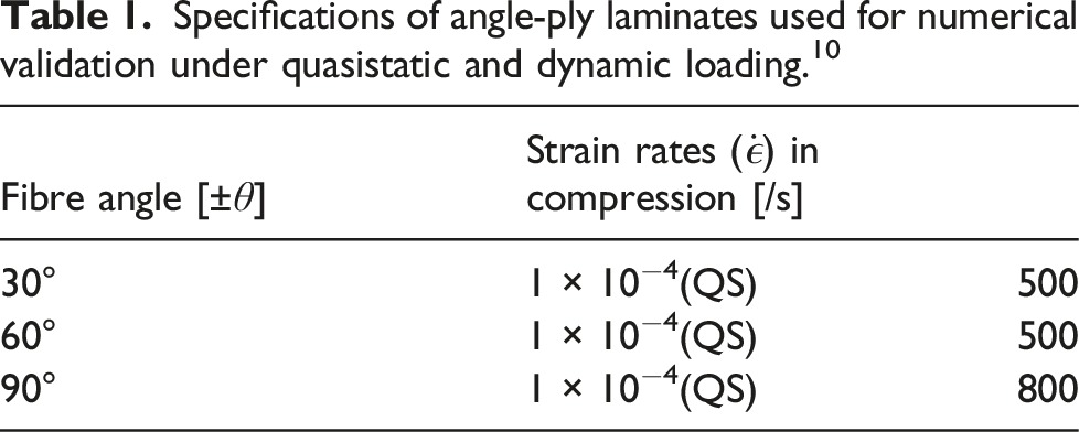
Uniaxial compression tests were performed on angle-ply laminates from an IM7/8552 carbon epoxy composite under quasi-static and dynamic loads by Schaefer et al. 10 Angle-ply samples of [±θ]14s were produced, where θ = 15°, 30°, 45°, 60°, 75°and 90° alternating the orientation of the layer after each ply during the lay-up.
The ±90° laminate is simply a unidirectional plate tested in the direction transverse to the fibres. The IM7/8552 prepreg was cured to produce a consistent composite laminate with a fibre volume fraction, v f = 0.58 and a layer thickness, t = 0.14 mm. The samples of dimensions 7.82 × 7.82 × 25.4 mm were then cut from the laminate. Strain rates greater than 500/s were achieved in dynamic tests, carried out in split Hopkinson bar setups, while in quasi-static loading, a servohydraulic test machine (Instron 8500) was used to test the strain rate value of the order of 10−4/s.
The applied boundary conditions are represented in Figure 2(a) and correspond to the experimental testing boundary conditions in compression. The applied velocity is Considered angle-ply composite laminate subjected to compression velocity loading. (a) Geometry of the specimen with boundary conditions and (b) 3D FE model with cohesive surfaces between each ply. Specifications of angle-ply laminates used for numerical validation under quasistatic and dynamic loading.
10
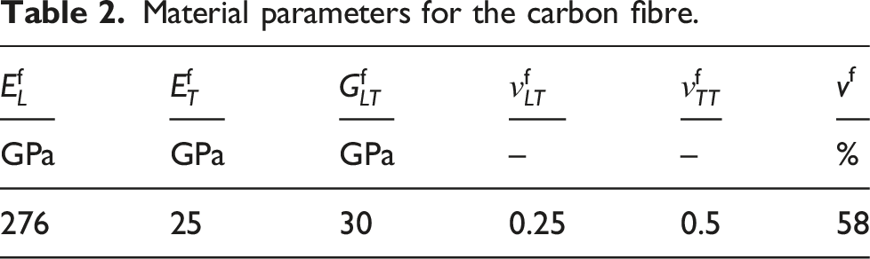
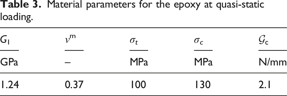
Material parameters for the carbon fibre. Material parameters for the epoxy at quasi-static loading.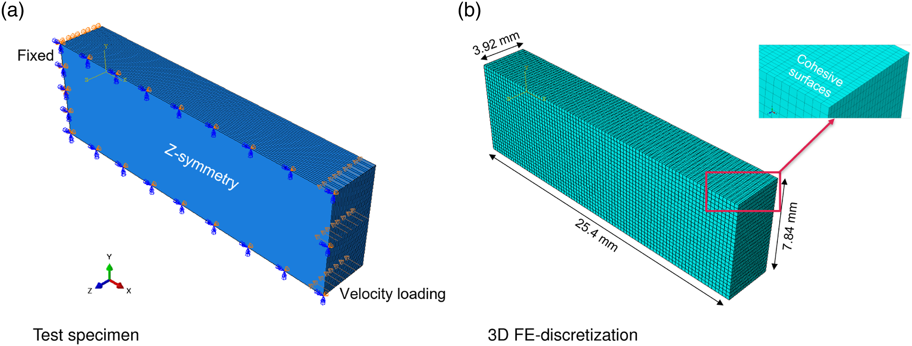
In simulations, an effective quasistatic shear modulus
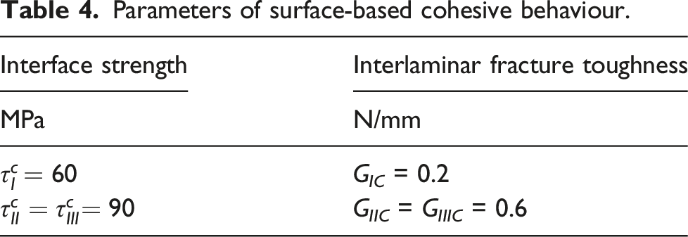
Parameters of surface-based cohesive behaviour.
Calibration of model parameters at the ply level
An approach based on numerical optimization, using the least square method, is applied to estimate viscoelastic-viscoplastic parameters for the epoxy matrix material, as explained in.22,23 In this approach, a calibration routine finds the dynamic model parameters by minimizing the error between homogenized material response at a material point and the uniaxial stress-strain response from the experiments. The identification of the model parameters at the ply level is based on calibration of the 30° off-axis specimen in compression. 9 For calibration, the constitutive FORTRAN VUMAT driver for the ply response is implemented in MATLAB to handle uniaxial compression at the material point level relative to the compression tests in. 9 Note that the experimental strains were measured locally using strain gauges. Therefore, calibration is based on linking the strain at the material point to the experimental strain gauge signal, i.e. assuming uniform strains. We emphasise that calibration is considered up to the point (usually peak stress) where strain localisation begins in the test specimen.
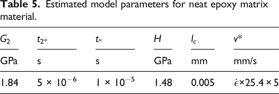
Estimated model parameters for neat epoxy matrix material.
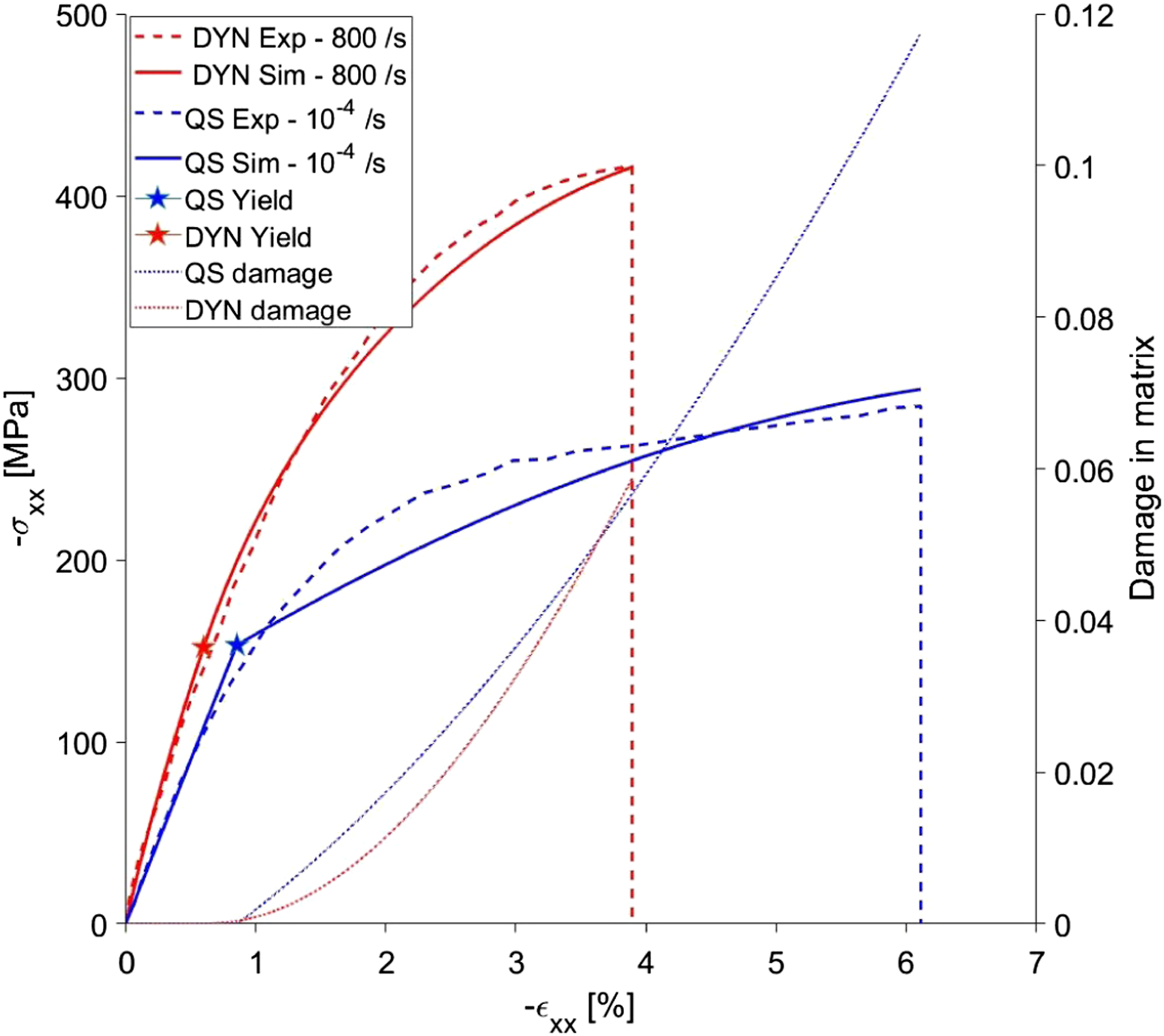
Comparison of experiments and uniaxial stress-strain predictions of the material points in compression under quasistatic and dynamic loading for a 30°off-axis specimen. The coloured stars represent the onset of yielding in the matrix.
Numerical validation
Finite element analysis
The numerical results are presented in this section and compared to the experimental results.
Based on published experimental data,9,10 including laminate specifications and experimental test results, finite element simulation is performed using the Abaqus/Explicit solver. The strain-rate-dependent damage model is implemented through a user-defined material (VUMAT) subroutine. The compressive behaviour of IM7/8552 angle-ply composite laminates is investigated. The laminate specifications and mechanical properties of the constituents are shown in Tables 1–3, respectively.
The explicit integration scheme, based on backward Euler method, element deletion technique, together with enhanced hourglass, is used. Figure 2(b) shows the numerical finite element model. The laminate is modelled with one element per ply along the thickness direction. Reduced integration of 8-node solid elements C3D8R is used to discretise the model. Convergence is achieved with a solid element of 0.3 × 0.3 × 0.3 mm3 which results in about 2200 elements to discretize the single ply as shown in Figure 2(b). Cohesive surfaces are defined for all ply-to-ply contact interfaces. The parameters of the behaviour of the cohesive interface are reported in Table 4.
The model parameters are estimated based on the 30° off-axis experiments using calibration as discussed in Section on page 11. This set of model parameters is used to validate the material model by predicting intra- and interlaminar failure of IM7/8552 angle-ply composite laminates at different compression strain rates. An average uniaxial strain in the xy plane and an average axial stress on the yz plane are used to represent the uniaxial stress-strain curves, as shown in Figures 4(a)–6(a). In Figures 4(b) and 5(b), the view represents the top ply seen from below. The comparison between numerical predictions and experimental observations of a 30° laminate under quasistatic and dynamic loading and under compression is presented in Figure 4. Reasonable agreement is observed between the numerical and experimental curves (Figure 4(a)). Note that the softening and subsequent drop in average stress correspond to the localisation of the strain. Previous studies of mesh convergence for the rate-dependent damage model (8) have shown that the localised damage evolution is mesh objective.20,23 The stiffness predictions agree well with the experimental observations for the quasi-static and dynamic loadings. An overestimation of the strength prediction is observed under a dynamic load of 500/s. Figures 4(b)–4(c) show the FE predictions for dynamic intra- and interlaminar failure modes of a laminate ±30° at 500/s. A localised intralaminar failure is observed transverse to the loading direction. The localised deformation occurs on the loading surface. Figure 4(c) shows the distribution of out-of-plane intralaminar damage and delamination growth through the thickness of the laminate. The delamination begins and is mainly distributed in the upper plies close to the loading surface because of the lack of out-of-plane constraint at the free surface. Experimental and predicted stress-strain responses, FE predictions for dynamic damage growth in ±30° composite laminate in compression. Damage distribution maps α[ Experimental and predicted stress-strain responses, FE predictions for dynamic damage growth in ±60° composite laminate in compression. The damage distribution maps α are indicated by the coloured circles in 5a. (a) Averaged uniaxial stress-strain response under quasi-static and dynamic loading. (b) In-plane (X-Y) intralaminar damage growth at 500/s. (c) Out-of-plane (X-Z) intralaminar damage growth within the plies (top) and delamination in cohesive surfaces (bottom) at 500/s. Experimental and predicted stress-strain responses and FE predictions for dynamic failure in ±90° composite laminate in compression. The strain distribution maps, ϵ
xx
, are indicated by the coloured circles in 6a. Experimental images by Koerber et al.
8
ⓒ Elsevier. Reproduced with permission. (a) Averaged uniaxial stress-strain response under quasi-static and dynamic loading. (b) In-plane (X-Y) strain ϵ
xx
distribution predicted for 800/s and experimental strain measurement for 276/s. (c) Out-of-plane (X-Z) inclined shear bands predicted for 800/s and fractographic observation for 276/s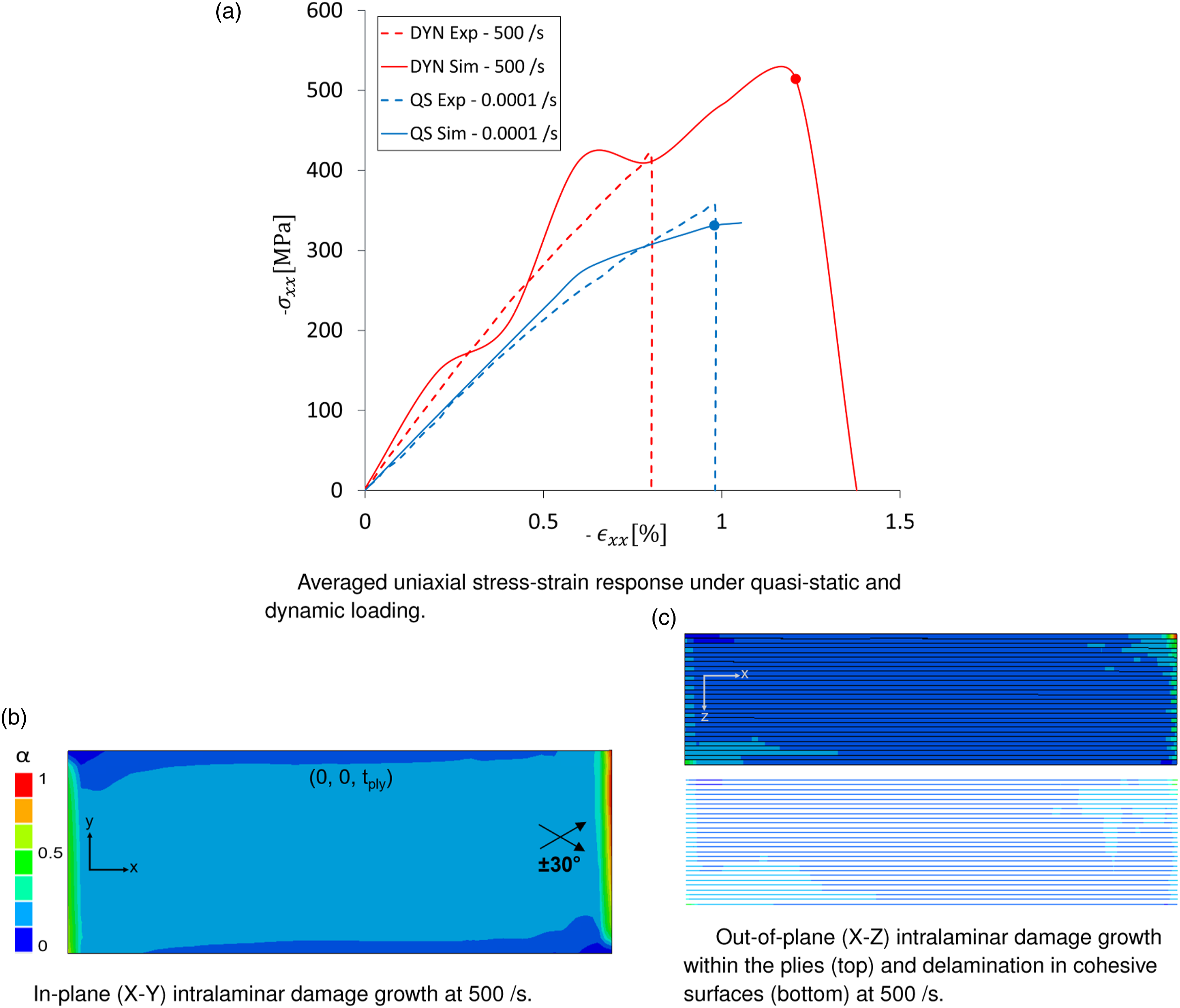
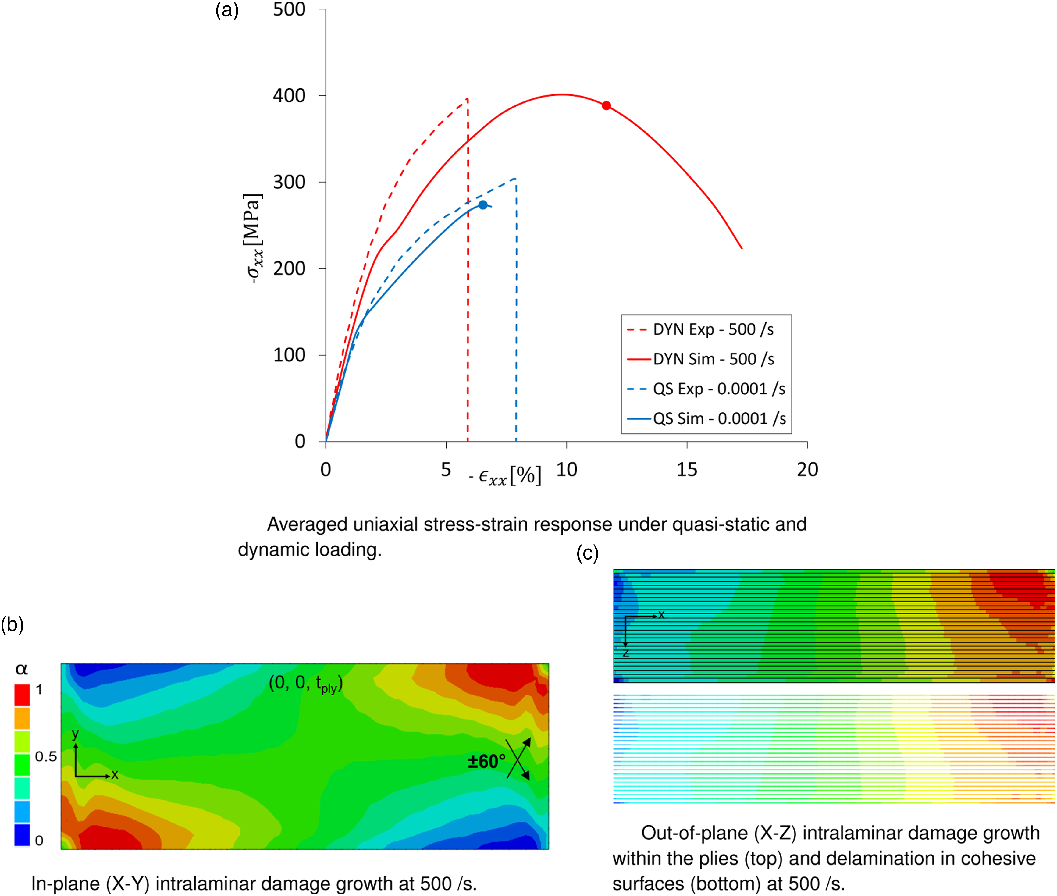
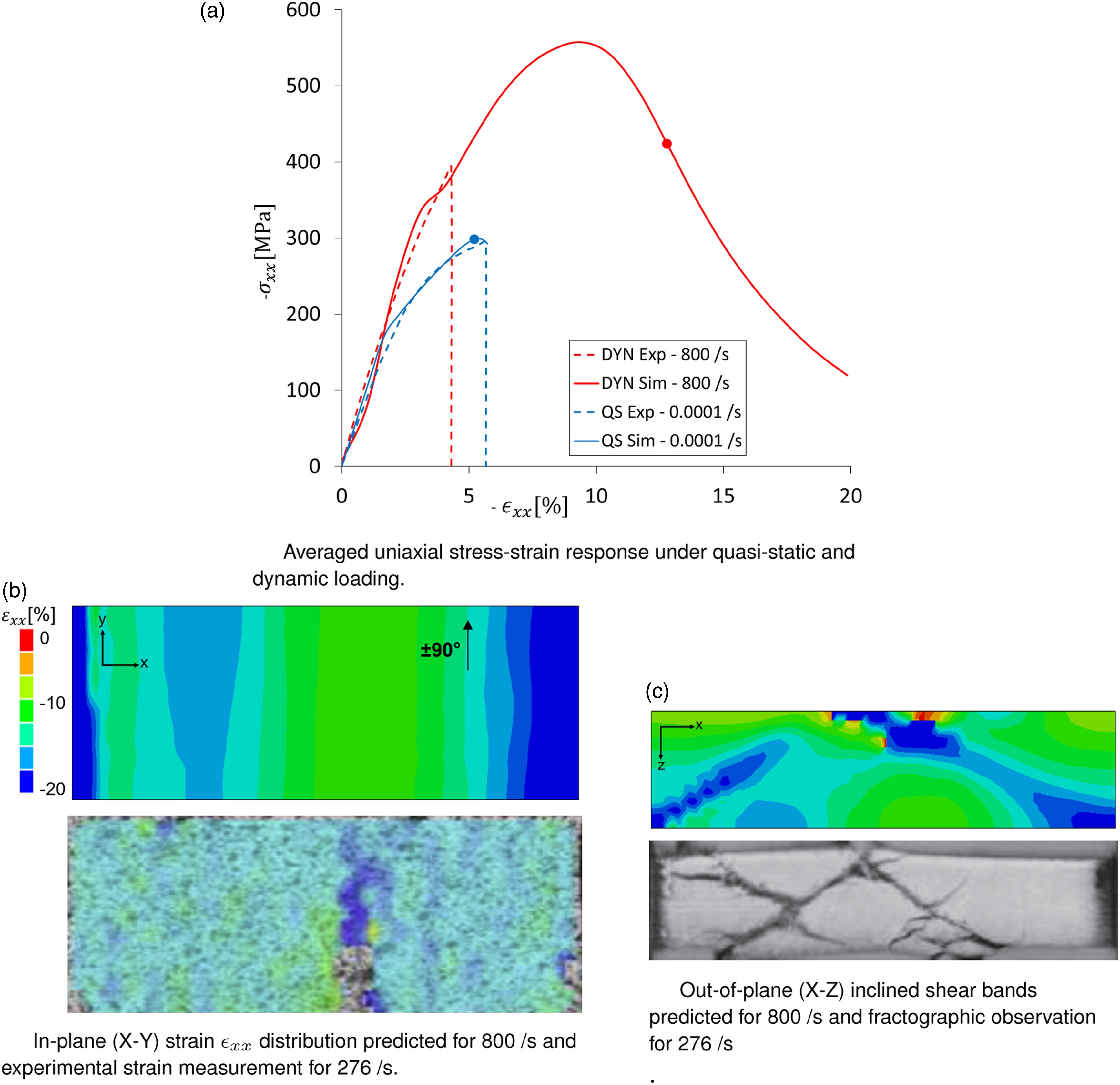
Figure 5(a) shows the averaged uni-axial stress-strain response at strain rates of 10−4/s and 500/s in compression of ±60° laminate. Under quasistatic and dynamic loading, good agreement is observed for stiffness and strength prediction. The ±60° laminate failed in the plane and through the thickness. In Figure 5(a) and (b) localised intralaminar failure is observed in the plane. Failure in the plane begins in the corner region of the sample and spreads along the loading direction, due to the forced rotation of the ±60° fibres in the upper layer and the lack of support on the free surfaces. Damage to the interlaminar delamination is seen in Figure 5(c). A progression of through-thickness damage is observed on the loading surface due to the lack of support at the free top surface. Figure 5(c) further illustrates the interaction between the intralaminar damage detected by the ply model and the interlaminar delamination detected by the cohesive surface model. In Figure 5(c), it can be seen that the delamination begins on the free surface of the specimen. The interactive nature of the out-of-plane intra- and interlaminar failure is also visible in the xz plane. It is well known that the onset of delamination can be related to matrix cracking and that the extent of delaminations can be related to zones with matrix cracking, that is, intralaminar damage. An early modelling study of how matrix cracks initiate delamination was provided in. 39 More recently, Zubillaga et al. 40 developed the MCID criterion for matrix crack-induced delamination.
Figure 6(a) illustrates the experimental and numerical averaged uniaxial stress-strain curves at strain rates of 10−4/s and 800/s for a ±90° laminate in compression (corresponding to transverse compression). Good agreement is obtained for the prediction of stiffness and an overprediction of strength for a dynamic loading of 500/s. Under quasi-static loading, good agreement is obtained for stiffness and strength prediction. Patterns of the in-plane shear band can be observed in Figure 6(b). Multiple localised in-plane shear bands are obtained transverse to the loading direction at 800/s in the xy-plane. These patterns are in line with the observations of Koerber et al. 8 with dynamic experimental tests performed on the IM7/8552 material system under transverse compression. Figure 6(c) illustrates the out-of-plane shear localisation that occurs in the ±90° laminate under dynamic compression. Multiple shear bands circa 45° from the loading direction are observed in the xz-plane. A similar observation, but at a lower loading rate, was made by Koerber et al. 8
Discussion
Figure 7 shows a comparison of experimental observations and numerical predictions for 15°, 45°, 75°and 90° off-axis specimens with IM7/8552 unidirectional plies under quasi-static and dynamic loading and in compression. The representation of the results is similar to that described in the section on page 11. Comparison of experiments and material point uniaxial stress-strain predictions in compression under quasi-static and dynamic loading for different off-axis specimens. The coloured stars represent the beginning of the yielding. (a) Comparison of 15° off-axis response. (b) Comparison of 45° off-axis response. (c) Comparison of 75° off-axis response. (d) Comparison of 90° off-axis response.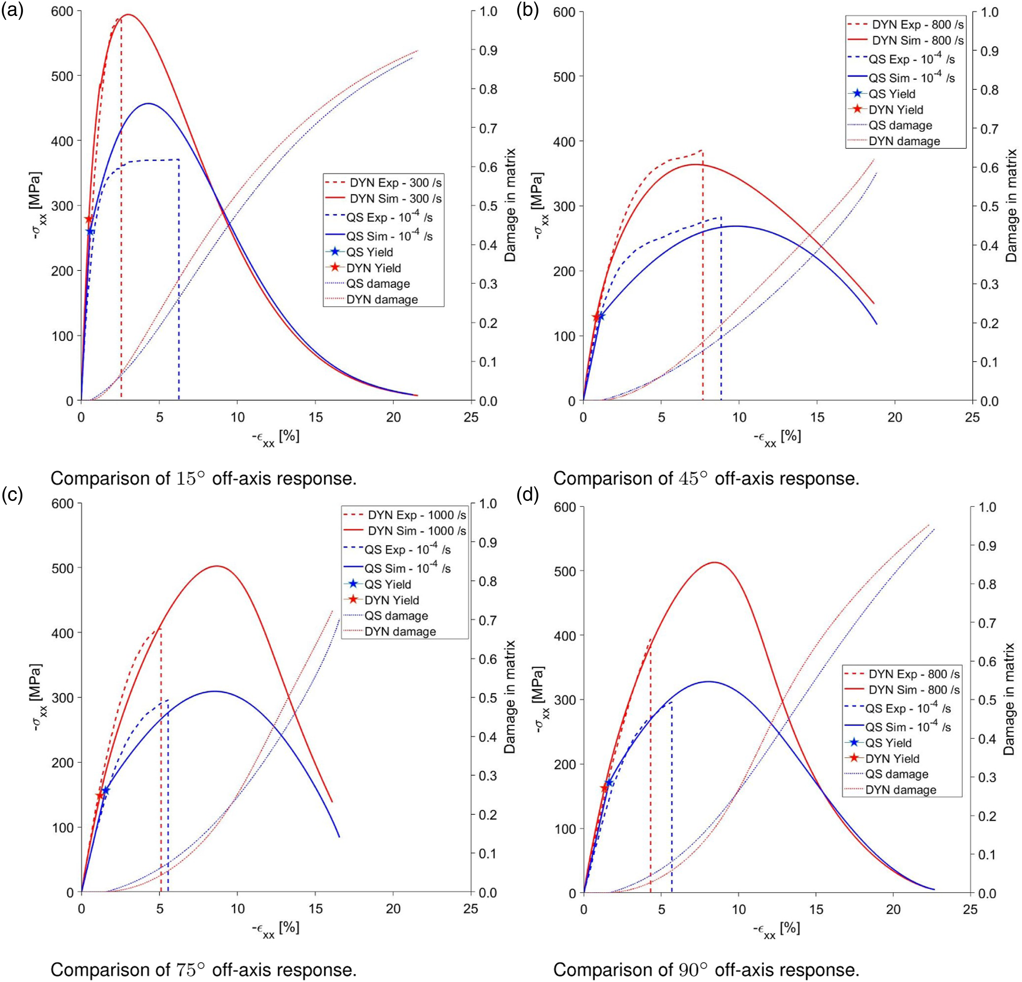
Based on the FORTRAN VUMAT implementation of the 3D constitutive ply model, a Matlab code was developed to describe the uniaxial compressive ply tests at the material point level. Predictions at the material point level assume homogeneous straining in the specimens, allowing the calibration of the material point level considered to be based on the prelocalized ply behaviour. Therefore, numerical validations are based on model parameters obtained after calibrating on a sample 30° off-axis with quasistatic and dynamic compression loading (see Section on page 11). Figure 7 shows that good agreement is achieved between compressive experimental observations and numerical predictions for different off-axis specimens with IM7/8552 unidirectional plies under quasistatic and dynamic loading. In particular, the quasi-static results are better predicted than in Ref. 22. This is due to the introduction of an additional model parameter, that is, isotropic hardening, which is estimated by calibration, as explained on page 11 (see Table 5). The formulation is described in the section on page 5. This parameter is used to model the strain hardening behaviour of the matrix caused by the reorientation of the covalent chains during plastic deformation, where the straightening of the chains results in strain hardening. 41 We also observe an increase in initial stiffness for the dynamic case compared to the static model responses because of the rate-sensitive viscoelastic polymer matrix constituent. Note that the experimental curves in Figure 7 reflect the average strain in the region where the strain was measured (a central strain gauge), while the predictions for the material point reflect the response up to the ultimate failure in the region with strain localisation. Therefore, the measured failure strain in the experiments is much lower than the ultimate failure strain of the material (see Figure 7).
The resulting model response of the neat resin for quasistatic loading is shown in Figure 8. In view of the expected behaviour of the polymer, it was observed that the model reasonably well predicts the stiffness up to the onset of the yield in compression. Once the yield stress is reached, the model response is then governed by viscoplasticity coupled to isotropic hardening and continuum damage. In general, a good agreement is obtained between the model response and the experiment (reproduced from
41
) in compression. Comparison of the predictions of the numerical model with the experimental results of the 8552 resin in compression under quasi-static loading.
41
The beginning of the yielding is shown by a coloured star.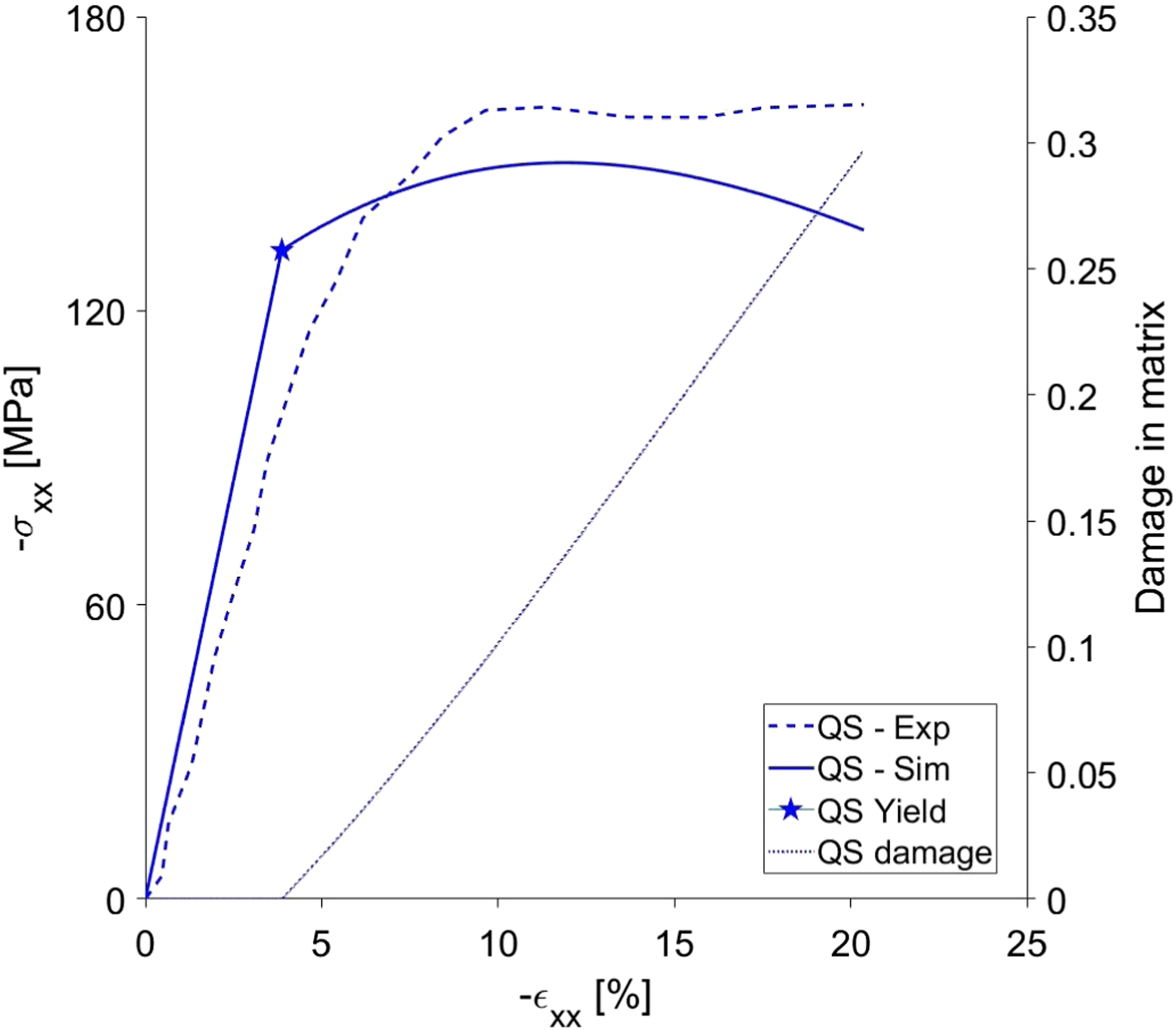
Conclusions
A strain rate-dependent ply level damage model has been successfully applied in FE modelling of quasistatic and dynamic compressive failure processes of angle ply laminates from IM7/8552 carbon/epoxy. The investigation was carried out for various strain rates using Abaqus/Explicit, where the interlaminar behaviour was described by a standard Abaqus traction-separation law. The ply-level strain-rate effects were described by a recently reported homogenised material model involving elastic transversely isotropic carbon fibres embedded in a viscoelastic-viscoplastic polymer matrix. The strain hardening was modelled by including isotropic hardening in the viscoplastic response of the matrix. Model predictions were validated against the experimentally observed rate-dependent damage growth of angle-ply laminates. 10 Relatively good qualitative and quantitative correlation was achieved between the stress-strain response of the numerical models and the experimental results for the angle-ply laminates of IM7/8552. The predicted growth of intra- and interlaminar damage to composite laminates is consistent with experimental observations and confirms the effectiveness of the proposed strain-rate-dependent damage model. Note that strains will be relatively uniform until strain localisation, which is followed by rapid damage growth and subsequent final failure. It appears that the actual delamination growth of each interface is generally triggered by growth of the damage at the ply level.
Footnotes
Declaration of conflicting interests
The author(s) declared no potential conflicts of interest with respect to the research, authorship, and/or publication of this article.
Funding
The author(s) disclosed receipt of the following financial support for the research, authorship, and/or publication of this article: This work was supported by the Swedish Foundation for Strategic Research (SSF) through the contract dnr FID16-0041 and by the internal SK-development funds of RISE.
Data Availability Statement
The data given in this article is available on request.