
Abstract
Interleaving is a well-recognized method for enhancing the interlaminar fracture toughness of composite materials. However, theoretical toughness is often not realized since cracks tend to propagate through regions of lower toughness. While most studies have focused on the effect of interleaf properties, e.g., thickness and interleaf resin properties, on composite interlaminar fracture toughness, the effect of matrix resin properties on interleaved composite toughness has been overlooked. Recently, we hypothesized that there is a relationship between toughness translation and the ratio of matrix to interleaf resin toughness. In this work, we use additive manufacturing to test this hypothesis with a range of resins in interleaved composite. Toughness is quantified via mode I delamination resistance. Our results confirm our hypothesis that the ratio of matrix to interleaf resin fracture toughness, i.e., the ratio of
Keywords
Introduction
Laminated fiber reinforced composites are multilayered structures with exceptional strength and stiffness. However, their modest interlaminar toughness and susceptibility to delamination failure present significant challenges.1–3 Interlaminar toughening offers a promising solution to these limitations, enabling the broader utilization of composites in high-end applications.4–6 Currently, three major approaches to interlaminar toughening exist: through-thickness reinforcement (z-pinning), matrix toughening, and interlayer toughening (interleaving). 1 Each technique provides a distinct level of toughness improvement, but also comes with specific drawbacks that require careful consideration, namely, possible disturbance of fiber architecture, reduction of fiber volume fraction, and loss of mechanical properties.7,8
Matrix toughening is one of the first methods employed to reduce delamination failure. This method has the least effect on fiber volume fraction for matrices with reasonable viscosity. Previously, it was thought that incorporating a tough matrix would directly enhance interlaminar toughness. However, subsequent studies revealed that highly toughened matrices are not as effective in toughening the composite due to the restriction of the plastic deformation zone.9–11 In other words, the interlaminar region size significantly affects resistance to crack growth. The region must be comparable to the plastic deformation zone to achieve significant toughening of the composite. The process of introducing a thick resin rich layer (RRL) into the laminate to allow for plastic deformation and suppress crack growth is known as interleaving and is effective in improving both mode I and mode II interlaminar toughness.
The first-generation interleaf materials consisted of discrete thermoplastic or thermoset films placed between laminate layers. 12 However, incorporating RRL/interleafs in composite materials is not trivial using standard manufacturing techniques. One solution was to use fillers, such as fiber veils, particles, short fibers, and nano materials like graphene and carbon nanotubes, as spacers to control the interlayer thickness and expand the range of interleaf materials.13–16 Although these fillers offer processing advantages, they do not necessarily participate in the toughening phenomena.17,18 Therefore, it is not clear wether fillers are need to be used in interleaving methods to achieve toughened composite materials. Furthermore, the use of fillers still limits the composite to a single resin.
Additive manufacturing offers a strategic platform for directly incorporating RRLs into composite parts and using multiple resins for laminate and interleaf. 19 In this technique, no fillers are required and the RRL thickness and chemistry can be prescribed accurately with a z-axis motor and different resin vats. 19
Under certain circumstances, the theoretical performance of interleaved composites can be predicted using Linear Elastic Fracture Mechanics (LEFM). For instance, when the interleaf is thick enough, i.e. on the length scale of the plastic zone size, and there is no other phenomenon such as fiber bridging, fracture of the composite satisfies plane strain conditions such that a cohesive failure is expected, and a composite interlaminar fracture toughness (
In heterogeneous systems where the interleaf material differs from the matrix, adhesive failure is commonly observed where cracks tend to propagate in the brittle matrix rather than cohesively through the tough interleaf.7,13,17,23 Despite reports of toughness improvement, such failure excludes the interleaf from the fracture process at an early stage and diminishes the improvement window. Intuitively, one can assume this occurs when the interleaf is stronger than the matrix, as the crack would follow the path of least resistance, i.e., the brittle matrix. We recently hypothesized that the ratio between the resin toughness in the lamina and the RRL is a key factor in achieving cohesive failure.
19
This argument is supported by Ni et al., who demonstrated through finite element simulation that if the interlayer bulk toughness (
In this work, we used a range of resins with incremental differences in fracture toughness to verify that there exists an ideal ratio of resin toughness for realizing cohesive failure and maximizing interlaminar toughness translation in interleaved composites. We utilized vat polymerization additive manufacturing, a previously validated method, to produce laminated composites with controlled RRL thickness and tested mode I interlaminar fracture toughness of control and interleaved composites with different combinations of resin. This technique is discussed in detail and compared with vacuum-assisted resin transfer molding in Idrees et al. 25 Note that controlled interleaved specimens could not be made without the use of additive manufacturing. 25 The results obtained are combined with findings from a previous study to establish a correlation between resins’ fracture toughness ratio, composite mode I fracture mechanisms, and overall toughness translation. 19
Materials and methods
Materials
DA2 is a stiff resin consisting of bisphenol A glycerolate dimethacrylate (Bis-GMA), ethoxylated bisphenol A dimethacrylate (Bis-EMA), and 1,6-hexanediol dimethacrylate (HDDMA) mixed at a 3:3:2 weight ratio, along with 0.7% wt of phenylbis (2,4,6 trimethylbenzoyl) phosphine oxide photoinitiator (PPO). DA2 mechanical and thermal properties were published by Tu et al. 26 DA5 is an in-house developed vinyl ester resin synthesized by reacting two types of epoxy resin, namely, Epon 828 and Epon 1001F, with methacrylic acid to produce methacrylated epoxy resin. Para-methyl styrene is added as a reactive diluent. The resin-diluent ratio is 65:35, respectively, and 0.7 wt% PPO is used as a photoinitiator. The formulation and properties of DA5 were published by McLaughlin and Palmese. 27 Additionally, a urethane acrylate commercial resin with the brand name “Tenacious” was purchased from Siraya Tech. The mechanical properties of Tenacious are published in reference.19,28 The DA2 and Tenacious were mixed at different weight ratios to formulate resins with varying fracture toughness, referred to here as DT-XX, where XX is a number representing the weight fraction of Tenacious in the mixture (∼40%–80%). DT-XX resins are formulated by mixing the two resins for one hour. Details about their formulation and mechanical and fracture properties were published in reference 28 A fabric, namely, plain weave E-glass with an areal density of 0.025 g/cm2, thickness of 0.025 cm and a single fiber diameter of ∼12.5 μm, was purchased from FiberGlast Developments Corp. The fabric contains general-purpose sizing.
Composite manufacturing
Figure 1 shows composite processing via vat polymerization additive manufacturing, using a process similar to what was previously described in reference.
19
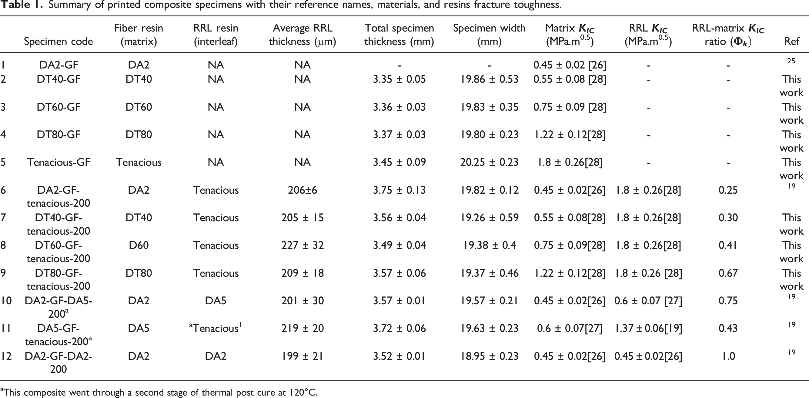
We utilized an ELEGOO MARS LCD (Liquid Crystal Display) printer equipped with a 405 nm LED to fabricate laminated composites using a modified technique that involved applying pressure on fiber mat during the printing process. This method allowed us to interchange the resin vat to incorporate different matrices, enabling the creation of resin-rich layers (RRLs). To cure the composites, we consolidated 4 layers of fiber mats at a time using the building platform and applied a 150 N of force. Subsequently, the cured fiber mats underwent exposure to a defined pattern of 405 nm light for a specified time. Our composite parts were made of 16 fiber mat layers, so the part was made in four steps; during printing, three rectangular specimens were produced simultaneously, with separate boundaries for easy handling. We swapped the resin vat to accommodate different resin types, specifically for the RRL printing. For RRLs printing, we employed a slicing thickness of 50 µm and an exposure time of 100 seconds, resulting in a ∼200 µm RRL. After printing, excess resin was wiped with a kimwipe saturated with isopropanol. The specimen was then dried and photo post-cured at 75°C for two hours. Finally, specimens were polished using a polishing wheel (Spectrum System 1000 polisher) and a series of coarse to fine grit sandpaper. The RRL thickness was measured using an optical microscope. Pre-cracked specimens were checked with a microscope to ensure that the crack tip was near the midplane of the RRL. Specimens with crack tips significantly off centered were observed but not tested. Table 1 provides additional details regarding the fabricated composites. (a) Schematics of the AM process used for fabrication of laminated composites with RRL, and (b) schematics of a DCB test specimen and our research question on how RRL and matrix fracture toughness translate to the final composite fracture toughness. Summary of printed composite specimens with their reference names, materials, and resins fracture toughness. aThis composite went through a second stage of thermal post cure at 120°C.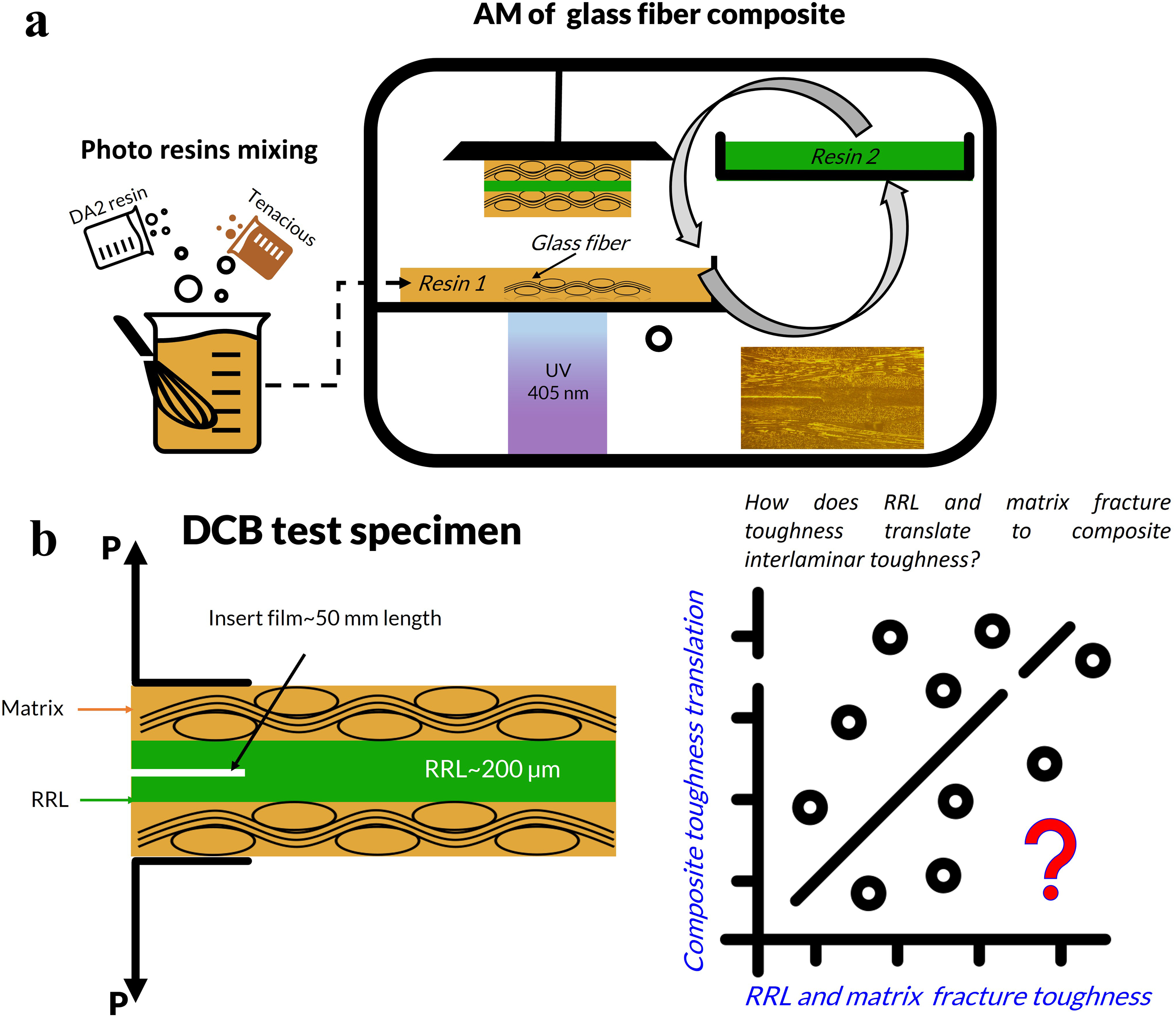
Mode I interlaminar fracture toughness, resin toughness, and resin fracture toughness
Mode I interlaminar fracture toughness tests were conducted according to ASTM D5528 standards using an Instron apparatus with a 1.0 kN load cell. Double cantilever beam (DCB) specimens, measuring ∼20 mm in width and 120 mm in length, were printed. An RRL of ∼200 µm thickness was incorporated into the interleaved specimens’ midplane. A precrack of approximately 50 mm in length was created using a 12.7 µm thick polyimide film. Aluminum piano hinges were attached to the specimens with a superglue adhesive, and the sides were marked for tracking crack length over time. Five specimens of each set were tested. The DCB test was conducted at room temperature and crosshead speed of 5.0 mm/min. The crack length was monitored using a video camera. When possible, the interlaminar fracture toughness parameter 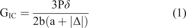
Results and discussion
Control composites mode I interlaminar fracture toughness
It is well established that mode I delamination failure occurs at lower energy levels than mode II and is influenced by the resin toughness (
The DCB test was used to investigate mode I interlaminar fracture toughness, and the resulting DCB test results of control laminates made with resins of varying toughness(a) DCB load displacement curves (b) R-curves, toughness vs. crack length (c) Laminates average initiation and steady state Snapshot of Tenacious-GF composite DCB test showing fiber bridging.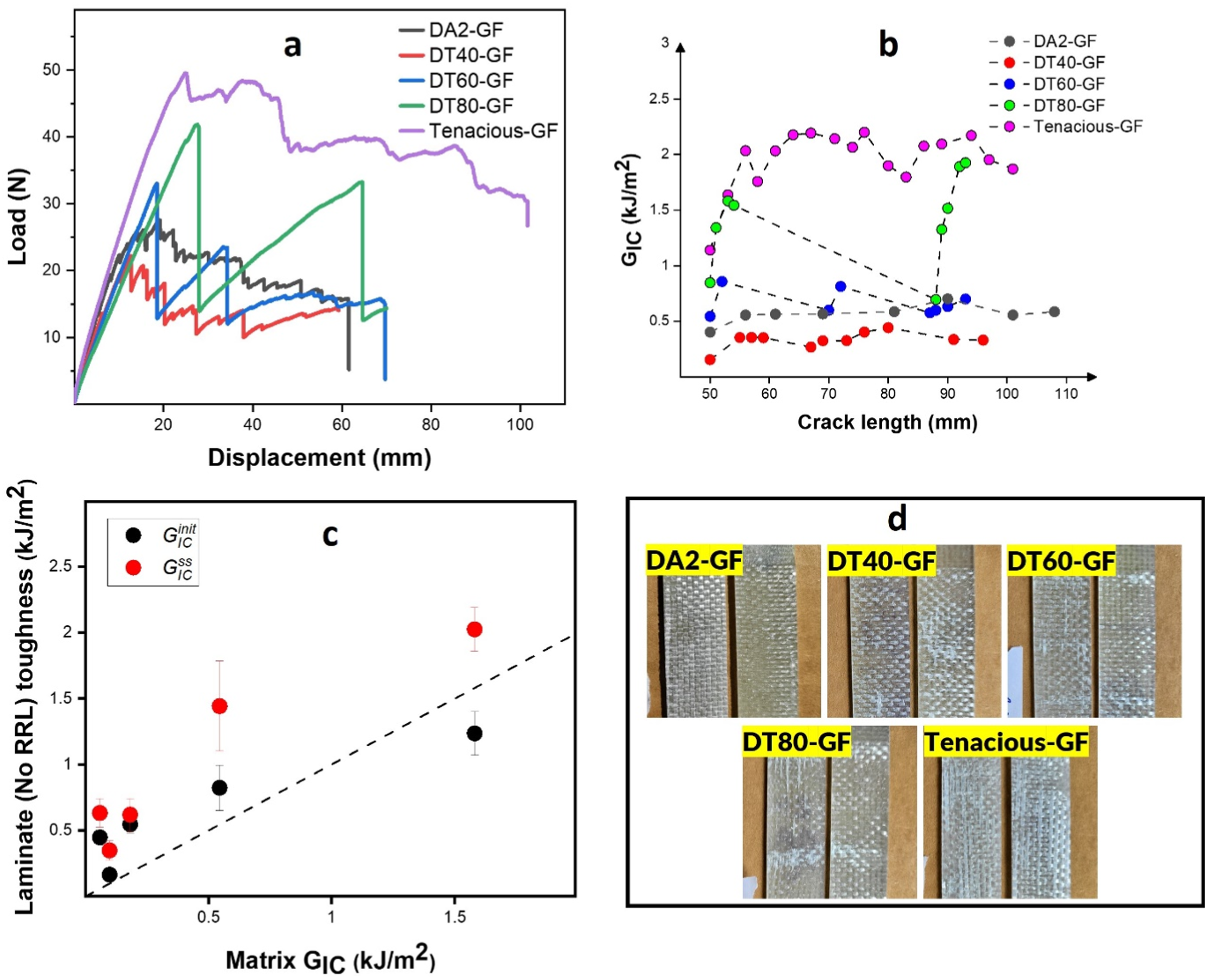
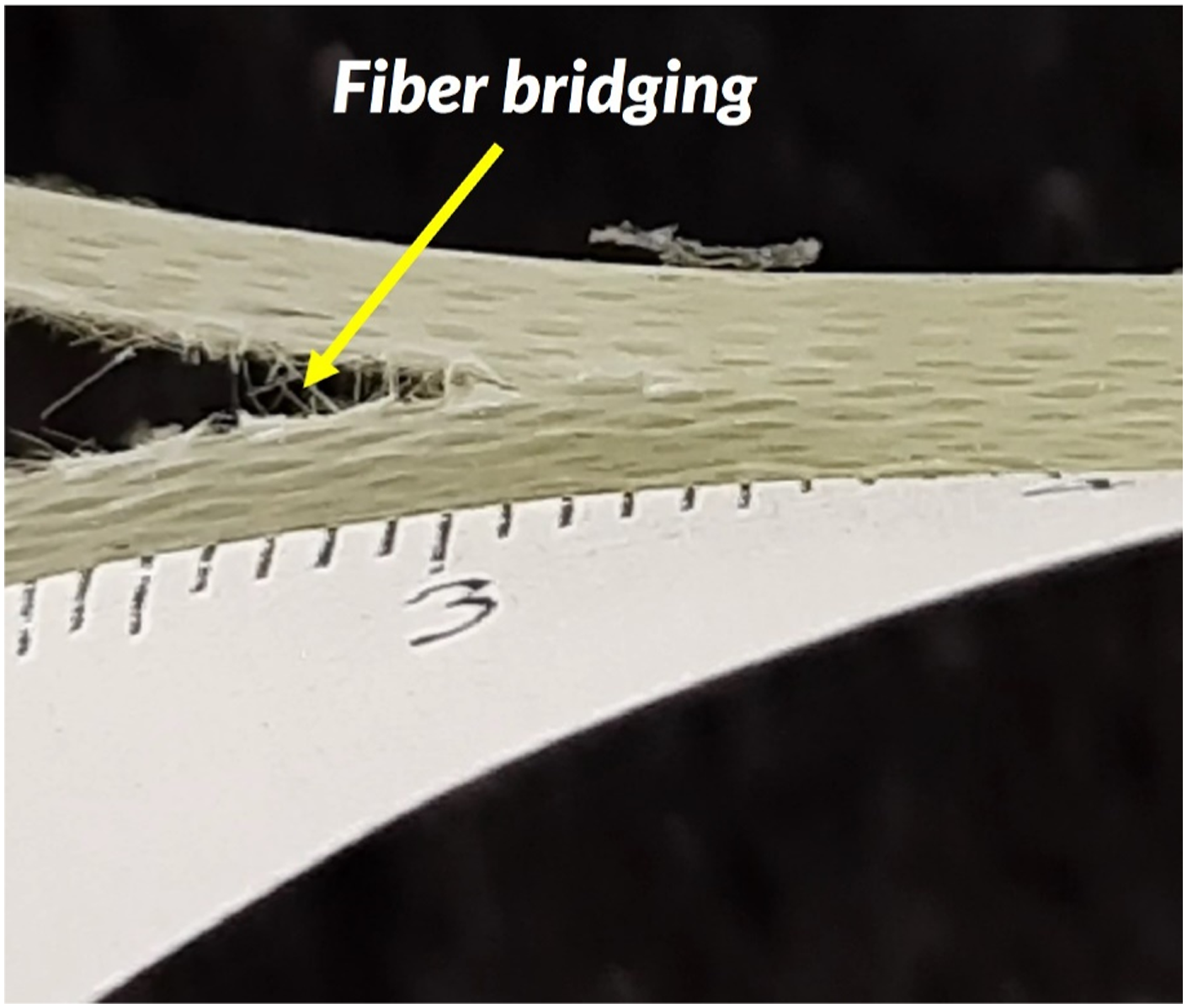
The load drops and unstable crack growth are reflected in the R-curves (see Figure 2(b)), where toughness is plotted as a function of crack length. Figure 2(b) shows fluctuations in toughness between an upper and lower bound, while DA2 and Tenacious reached a nearly steady state. In the case of DT80,
In Figure 2(c), we show the effect of matrix toughness on
The periodic interlaminar toughness observed in Figure 2 can be due to a range of factors. One explanation is a change in either the fiber-matrix interface properties or the matrix bulk properties. A study on vinyl ester and glass satin woven fabric showed that stick-slip behavior (unstable crack growth) increased with the concentration of the sizing agent, indicating that the interface was the primary contributor to this phenomenon. 39 Another explanation is the matrix’s sensitivity to the loading rate. A study on graphite PEEK (Polyether ether ketone) demonstrated that stick-slip behavior was due to the ductile-to-brittle transition of the resin at different deformation rates. At low rates, stable crack growth was observed, while at high rates, unstable crack growth occurred when the cracks reached the boundaries. 36
The fracture surface of the DCB specimens (Figure 2(d)) showed signs of stick-slip behavior in the blended resins. DA2 composite failure exhibited clear adhesive failure, while blended resin composites showed significant resin presence on both fractured surfaces. The white regions in Figure 2(d), particularly for DT60 and DT80, correspond to the stick (crack arrest) region, where an increase in interlaminar toughness is observed, followed by long regions of cohesive failure. The length of unstable crack growth and the process zone increased with increasing resin toughness. This could be due to ductile-to-brittle transitions since the interfacial properties are not expected to differ greatly. Overall, even though Tenacious composites had the highest toughness, blending DA2 and Tenacious improved composite interlaminar toughness over the brittle DA2 resin composite.
Mode I interlaminar fracture toughness of interleaved composites
In this part, we examine the impact of matrix toughness on interleaved composite toughness, specifically focusing on the effect of Tenacious RRL (Resin Rich Layer) with a thickness of approximately 200 microns. The RRL is expected to enhance the interlaminar toughness of the composite, bringing it closer to the bulk toughness of the interleaf material. Theoretically, the interleaved composite toughness should equal the RRL resin toughness (1.5 kJ/m2) when the thickness is greater than the plastic deformation zone.19,20
Figure 4 shows the DCB test results for Tenacious interleaved composites. Figure 4(a) shows representative load-displacement curves for each specimen. Note that in all cases, the peak load is higher than the non-interleaved composites discussed in Figure 2. However, we still observe stick-slip behavior for certain resins, as evidenced by significant load drops. The improvement in fracture toughness is better seen in Figure 4(b). In all cases, the composite initiation toughness exceeds the steady state toughness, highlighting the role of the RRL in resisting crack initiation. Although the toughness decreases after initiation, the steady state Interleaved composites DCB results (a) DCB load-displacement curve, (b) R-curves, toughness as a function of crack length, (c) the effect of matrices toughness on interleaved composites performance, (d) Top view of DCB fracture surfaces of interleaved composites.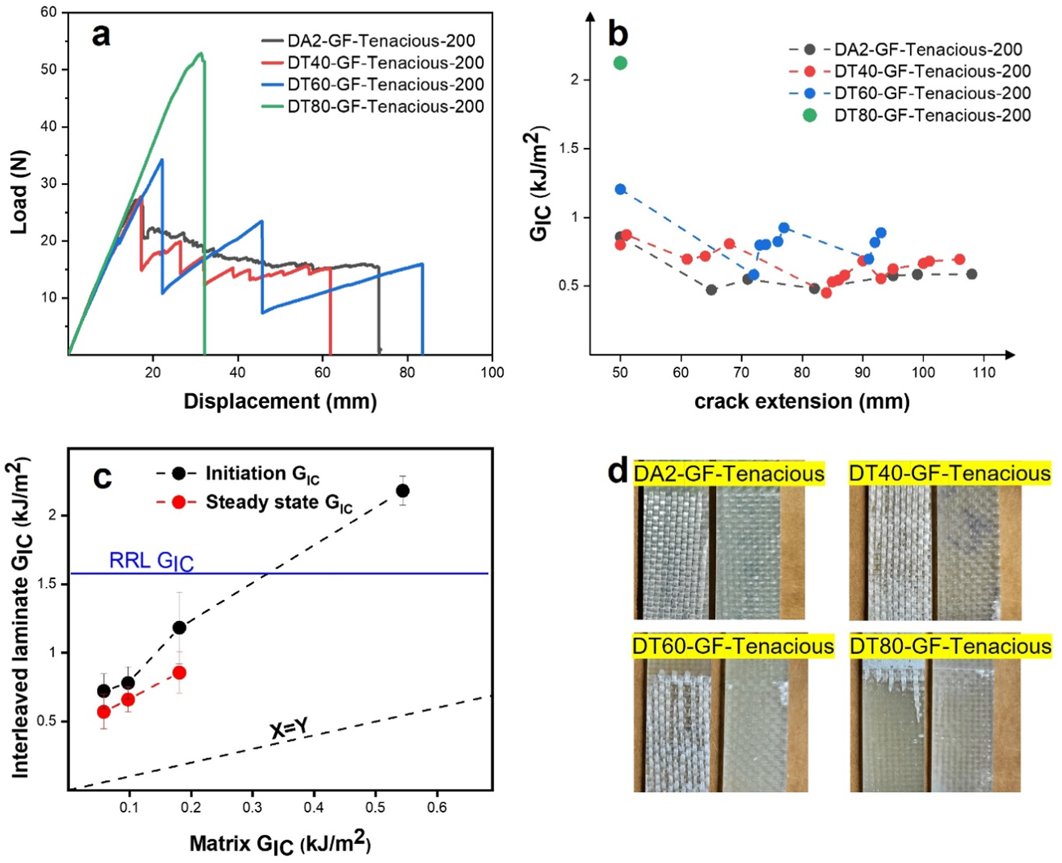
Figure 4(c) summarizes the average initiation and steady state toughness of the interleaved composites and compares them to matrix toughness. Unexpectedly, we observe that both initiation and steady state toughness improve linearly with increasing matrix toughness. Recall that we expected the fracture toughness to depend purely on the interleaf resin properties, which are constant for all specimens. This result is followed by unexpected differences in the fracture surface (Figure 4(d)), where the failure is predominantly adhesive for DA2, DT40, and DT60 interleaved composites. In the case of DT80, only a small adhesive zone (process zone) is observed near the insert tip followed by a fully planar cohesive failure, which is qualitiately consistent with literature.19,24 However, unlike the numerical simulation of Ni et al. which shows that a ratio of G IC (interlayer) to G IC (control laminate) greater than 10% leads to a transition from cohesive to adhesive failure, the experimental results show that this transition occurs at 180% difference in the G IC ratio.11,24,35
These findings clearly demonstrate that the failure and toughness of interleaved composites are strongly dependent on the matrix properties, which is not an expected result. In a previous study, we established that a minimum ratio of interleaf to matrix resin
Figure 5 relates toughness translation to individual The effect of RRL and matrix properties on toughness translation, (a) the effect of matrix fracture toughness on toughness translation, (b) the effect of RRL resin fracture toughness on toughness translation, (c) The combined effect of both RRL and matrix fracture toughness on toughness translation.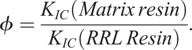
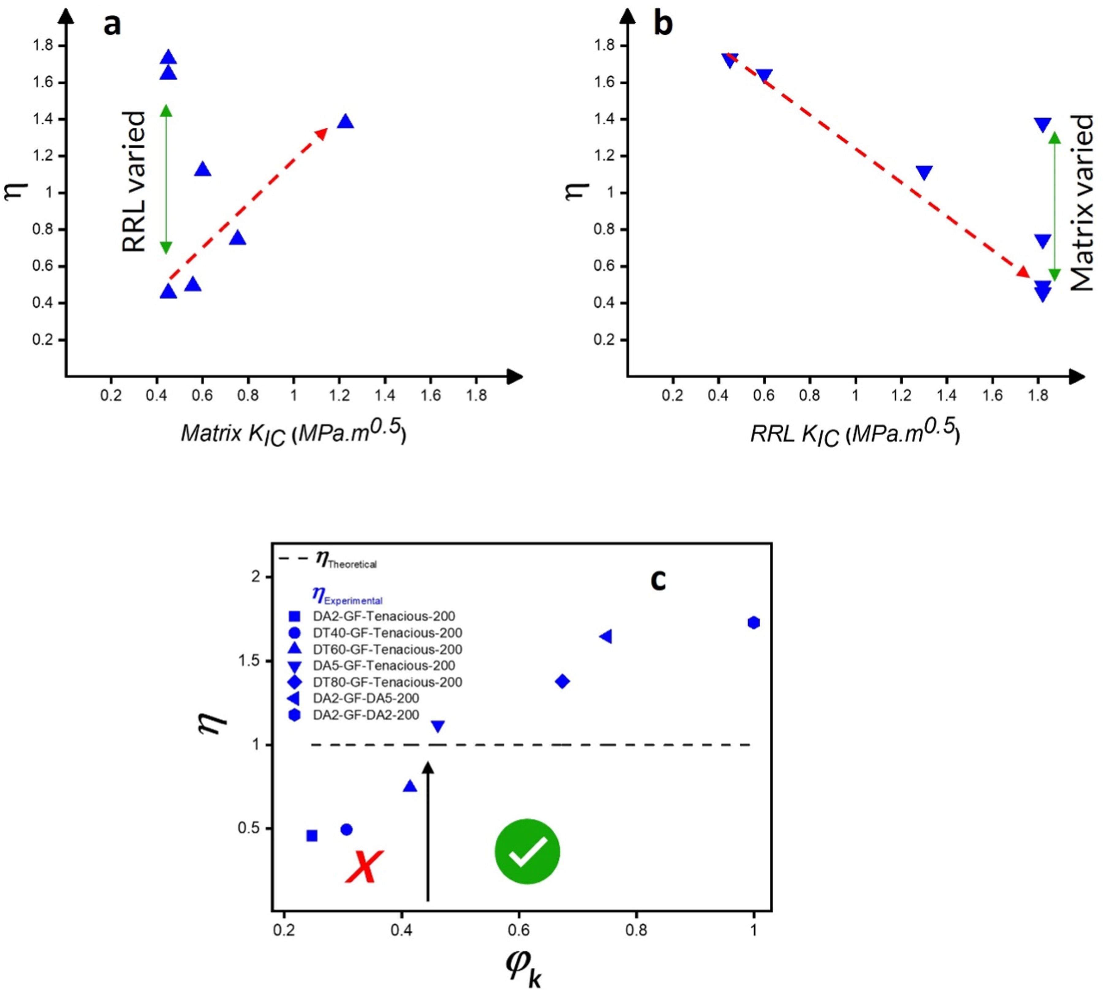
Figure 5(a) illustrates the influence of matrix
Conclusion
In this study, we utilized additive manufacturing to produce heterogeneous interleaved composites that could not be made using traditional manufacturing techniques. The AM method was used to control the RRL thickness and the resin chemistry for both the matrix and RRL. These specimens were used to determine a relationship between resin fracture toughness and composite interlaminar toughness. Firstly, we observed that both interleaved and non-interleaved composites exhibited increased initiation fracture toughness as the matrix toughness was enhanced. This indicates that the matrix resin plays a crucial role in determining the overall toughness of heterogeneous interleaved composites.
The results clearly indicate a correlation between the relative toughness of the matrix and the effectiveness of interleaving. More specifically, there exists a minimum fracture toughness ratio (
Footnotes
Acknowledgments
This research was sponsored by the Army Research Laboratory and was accomplished under Cooperative Agreement Number W911NF-17-2-0227. The views and conclusions contained in this document are those of the authors and should not be interpreted as representing the official policies, either expressed or implied, of the Army Research Laboratory or the U.S. Government. The U.S. Government is authorized to reproduce and distribute reprints for Government purposes not withstanding any copyright notation herein.
Declaration of conflicting interests
The author(s) declared no potential conflicts of interest with respect to the research, authorship, and/or publication of this article.
Funding
The author(s) disclosed receipt of the following financial support for the research, authorship, and/or publication of this article: This work was supported by the Army Research Laboratory (W911NF-17-2-0227).
Data Availability Statement
Data is available upon request.