
Abstract
Drilling composite materials is a critical stage in assembly, especially for structures that rely on mechanical fasteners. This research investigates the drilling of a hybrid composite made of an epoxy matrix reinforced with natural jute and Alfa fibers, focusing on three key cutting parameters: feed rate, spindle speed, and drill point angle. The study aims to assess how these factors affect thrust force, delamination, and the quality of the hole’s exit. Findings indicate that using a low feed rate, moderate spindle speed, and a smaller drill point angle helps reduce delamination and enhances hole surface finish. On the other hand, higher feed rates increase thrust force, raising the likelihood of damage and defects. The optimal conditions for minimizing thrust force and delamination while maintaining good hole quality involve a drill with a 110° point angle, a spindle speed of 1000 rpm, and low feed rates. Under these settings, thrust force remains low—ranging from 32.38 N at 50 mm/min to 26.07 N at 150 mm/min—while the delamination factor stays minimal, peaking at 1.052 even at higher feed rates. These findings emphasize the significance of carefully choosing cutting parameters to maintain composite integrity and enhance drilling efficiency. The study highlights the need to balance productivity with precision, optimizing cutting conditions to reduce damage and ensure the structural reliability of hybrid composites.
Introduction
Composite materials utilising plant fibres have attracted significant attention in recent years, fuelled by the expansion of the aeronautical, aerospace, defence, and automotive sectors. Their ability to address today’s economic and environmental issues is what sparked this attention1,2 as well as their superior mechanical and structural properties, such as lightweight nature, higher stiffness, and ease of manufacturing.3–6 Recent studies highlight the essential role of these materials in the transition towards economic, sustainable, and more environmentally friendly production.7,8 For example, the work of Mohanty et al. 9 have demonstrated that the use of plant fiber-reinforced composites can reduce the carbon footprint of materials while maintaining mechanical performance comparable to conventional alternatives. Bark fibers, including jute, palm, sisal, alfa, luffa, etc., are among the most commonly used natural fibers in composites.10–14 These materials, combined with polymer matrices, offer a sustainable alternative to traditional synthetic fibre-based composites, such as glass or carbon fiber. Alfa is a xerophytic grass belonging to the Poaceae family, characterised by its cylindrical stems that can reach up to 1 m in height. 15 It thrives in dense clumps within semi-arid regions of North Africa, notably in Algeria, Morocco and Tunisia, favoring dry, alkaline soils. 16 The fibers of Alfa are abundant and readily available in these areas, making them a valuable natural resource, are lightweight, strong and biodegradable. They exhibit commendable mechanical properties, such as, the Young’s modulus of the elementary fiber of Alfa is close to 13.4 GPa, for a tensile strength of 944 MPa, 17 rendering them suitable for various industrial applications, including the production of reinforced composites. They are used in composites as reinforcement for polymer composites.16,18–20 The combination of various reinforcing fibers with a polymer matrix during manufacturing results in a hybrid composite with unique properties that cannot be achieved with a single material. This type of composite offers ease of fabrication, high resistance to impact and water, lightweight characteristics, strong damping capacity and a reduced environmental impact.21–24 Natural fiber-based composites have limited weldability, so their assembly with other materials or fastening elements requires the use of alternative joining methods. 25 Drilling is one of the most widely used assembly methods, 26 it involves creating precise holes in a material. Drilling composites differs from drilling metals due to their anisotropic and non-uniform nature. Several factors resulting from this operation, such as delamination and thrust force, can influence their physical and mechanical properties.27,28 Compared to synthetic fibers like CFRP and GFRP, which have been widely investigated due to their superior mechanical properties and extensive industrial use, natural fiber composites offer advantages in terms of machining. While synthetic fiber composites require higher cutting forces and lead to significant tool wear and fiber damage,29,30 machining natural fiber composites, such as alfa/jute-reinforced materials, tends to be less demanding, resulting in lower cutting forces and reduced tool wear.31,32 Given these benefits, natural fiber composites are gaining attention as sustainable and machinable alternatives in various applications.
The impact of machining parameters on natural fiber composites has been the subject of extensive studies, demonstrating that optimal conditions can minimize defects and improve performance.31–34It has been observed that feed rate, spindle speed, and point angle are critical parameters influencing thrust force, delamination, fiber breakage and pull-out, as well as the deterioration of hole quality.35,36 Many researchers have focused on these issues by conducting in-depth studies to rigorously identify and select the most appropriate cutting parameters. Their goal is to optimize cutting conditions to minimize the various types of damage that can occur, while improving the quality of machined surfaces and extending tool life.12,37,38 Barik et al. 15 provided a detailed comparison of TiAlN-coated, TiN-coated and uncoated drills for machining bidirectional woven carbon fiber reinforced plastic (CFRP) laminates. The research highlights that using a TiN-coated drill, in combination with a low feed (0.025 mm/rev) and high spindle speed (3200 rpm), significantly reduces delamination (1.046). This combination promotes a more uniform thrust force and an appropriate machining torque, thereby enhancing the surface quality of the drilled holes.
The study of Mohd et al 39 examined the impact of different point angles (85°, 118° and 130°) on thrust force and delamination during the drilling of HFRP composites. The results showed that a small drill point angle and a low feed rate can reduce thrust force, leading to a reduction in the damage factor at the entry and exit of the holes. Deepak et al 40 used three drill point angles (90°, 118° and 135°) and three levels of spindle speed and feed rate for drilling flax/PP composites. The results indicated that the highest delamination factor was recorded with the 135° point angle drill. A low feed rate (0.05 mm/rev) and a medium spindle speed (1500–1800 rpm) were optimal parameters for each drill geometry. The research work of Rezghi et al 41 focused on the effect of the point angle on thrust force and delamination in woven jute fiber-reinforced polymer composites. Drilling was carried out using three drills with distinct geometries (118°, 120° and 130°) and different feed rates and spindle speeds. The results revealed that the feed rate is the cutting parameter with the most significant influence on thrust force, regardless of the drill type. Additionally, the drill with a 118° point angle generated lower thrust force and delamination factor compared to the other drills. The study by Patel et al 42 compared point angles of 90°, 118° and 135° during the drilling of banana fiber-reinforced polyester composites. Drilling was performed using different feed rates (0.1, 0.2 and 0.3 mm/rev), spindle speeds (1000, 2000, 3000 rpm), and drill point angles (90°, 104° and 118°). The results showed that thrust force and delamination factor increased with an increase in drill point angle and feed rate. Conversely, the delamination factor decreased with an increase in spindle speed and point angle. The optimal values for thrust force and delamination factor were achieved at a point angle of 90°, a spindle speed of 1000 rpm, and a feed rate of 0.1 mm/rev. Barik et al. 43 investigated the wear behavior of uncoated, TiAlN-coated and TiN-coated carbide drills during the drilling of woven carbon fiber-reinforced polymer (CFRP) composites under consistent machining conditions. It established a direct correlation between increased flank wear and the deterioration of hole quality, including heightened delamination, surface roughness and circularity errors. Through third-level wavelet decomposition of thrust force and torque signals, the research identified low-frequency force wavelets as effective indicators of tool wear, while low-frequency torque wavelets were better predictors of hole quality. Among the tools tested, the TiN-coated drill exhibited superior performance, making it a recommended choice for industrial CFRP drilling applications. The study also highlighted that tool wear leads to a shift from cutting to tearing mechanisms, resulting in elevated temperatures and thermal degradation of the matrix, thereby compromising hole integrity. Dubey et al. 44 examined the drilling performance of Carbon/Glass hybrid composites with different stacking sequences to address machining challenges associated with the anisotropic nature of laminates. The fabrication of laminated composites using carbon and glass fibers was carried out in four stacking configurations: C4G4, C5G3, C6G2 and CG. By controlling spindle speed, feed rate and stacking order, the study identified an optimal configuration sample A (C4G4) which resulted in a low thrust force of 59.05 N and a minimal delamination factor of 1.0001. These findings demonstrate that the C4G4 stacking sequence offers a well-balanced solution for achieving high drilling efficiency.
This study examines in detail the drilling of hybrid composites, focusing on epoxy-based materials reinforced with natural jute and Alfa fibers. Hybrid composites reinforced with natural fibers, such as jute and Alfa, are gaining increasing interest in the industry due to their environmental benefits and good mechanical properties. Jute, valued for its flexibility and natural appearance, is widely used in the packaging sector. Its integration into composite materials helps reduce the ecological footprint while meeting the functional and aesthetic expectations of consumers. Alfa is used to produce ropes, fabrics, and paper. Several research studies have utilized different Alfa fibers as reinforcement for thermosetting and thermoplastic matrices.18,20,45,46
The selection of a hybrid composite combining Alfa and jute fibers with an epoxy resin matrix is based on a balanced combination of mechanical performance, cost-effectiveness, and environmental sustainability. Jute contributes strength and stiffness, while locally sourced, lightweight Alfa fibers enhance energy absorption. Their synergy results in a material that is both strong and lightweight. The epoxy resin ensures good fiber bonding and structural integrity. This hybridization enhances overall mechanical properties, particularly stiffness, while also lowering costs and reducing environmental impact through the use of renewable, biodegradable natural fibers. Such composites are well-suited for applications in the automotive, aerospace, construction, and furniture industries.
The originality of this article lies in the in-depth analysis of the drilling behavior of the hybrid composite material composed of unidirectional Alfa fibers and bidirectional jute with an epoxy matrix. This topic remains relatively unexplored in the scientific literature.
This study highlights the specific challenges associated with drilling this composite material, with a particular focus on the effect of cutting parameters and drill bit type on thrust force, delamination, and hole-induced damage. By providing new insights into the interactions between jute fibers, Alfa fibers, and the epoxy matrix during drilling, this research contributes to expanding the industrial application potential of this promising and eco-friendly hybrid composite.
Materials and methods
Material preparation
The composite laminate developed in this study is composed of a polymer matrix prepared by mixing 75% epoxy resin (VX100.00) with 25% hardener. This matrix serves as the binder that impregnates the fibers and solidifies to form the composite material (Figure 1(a)). Two types of natural fibers are used as reinforcement: bidirectional jute fabrics, known for their mechanical strength and durability (Figure 1(b)) and unidirectional Alfa fibers collected from the Boussaâda region in Algeria. The Alfa fibers have a surface mass of 600 g/cm2 and a density ranging from 0.89 to 2.10 g/cm3 (Figure 1(c)). A custom wooden mold is prepared, with its walls and base coated with wax to facilitate demolding. An initial layer of resin is poured into the mold to begin the lay-up process (Figure 1(d)). A layer of Alfa fibers is then placed into the mold, followed by the application of another resin layer using a roller to ensure thorough impregnation and the elimination of air bubbles, which is critical to the quality of the final composite (Figure 1(e)). The layers are stacked according to a precise sequence, comprising seven total layers, four jute layers and three Alfa layers, all oriented in the same direction to ensure uniform mechanical behavior. The stacking sequence begins and ends with Alfa fibers, alternating as follows: Alfa / Jute / Jute / Alfa / Jute / Jute / Alfa (Figure 1(f)). This configuration results in a fiber mass fraction of 33%, evenly divided between jute (16.5%) and Alfa (16.5%) and part 67 % epoxy resin and durcisseur. An effective resin impregnation and optimal adhesion between fibers and the matrix are crucial for the performance of fiber-reinforced composites. This involves the uniform application of resin onto clean, dry fibers, utilizing a roller to eliminate air bubbles and ensure thorough impregnation. Adequate compaction, often achieved using a mechanical press applying a constant load of 1000 N (Figure 1(g)), consolidates the layers and enhances interlaminar bonding. Finally, an appropriate curing time of 48 hours ensures the composite’s strength, durability, performance and reliability. Schematic illustrations of the manufacture of hybrid composite material.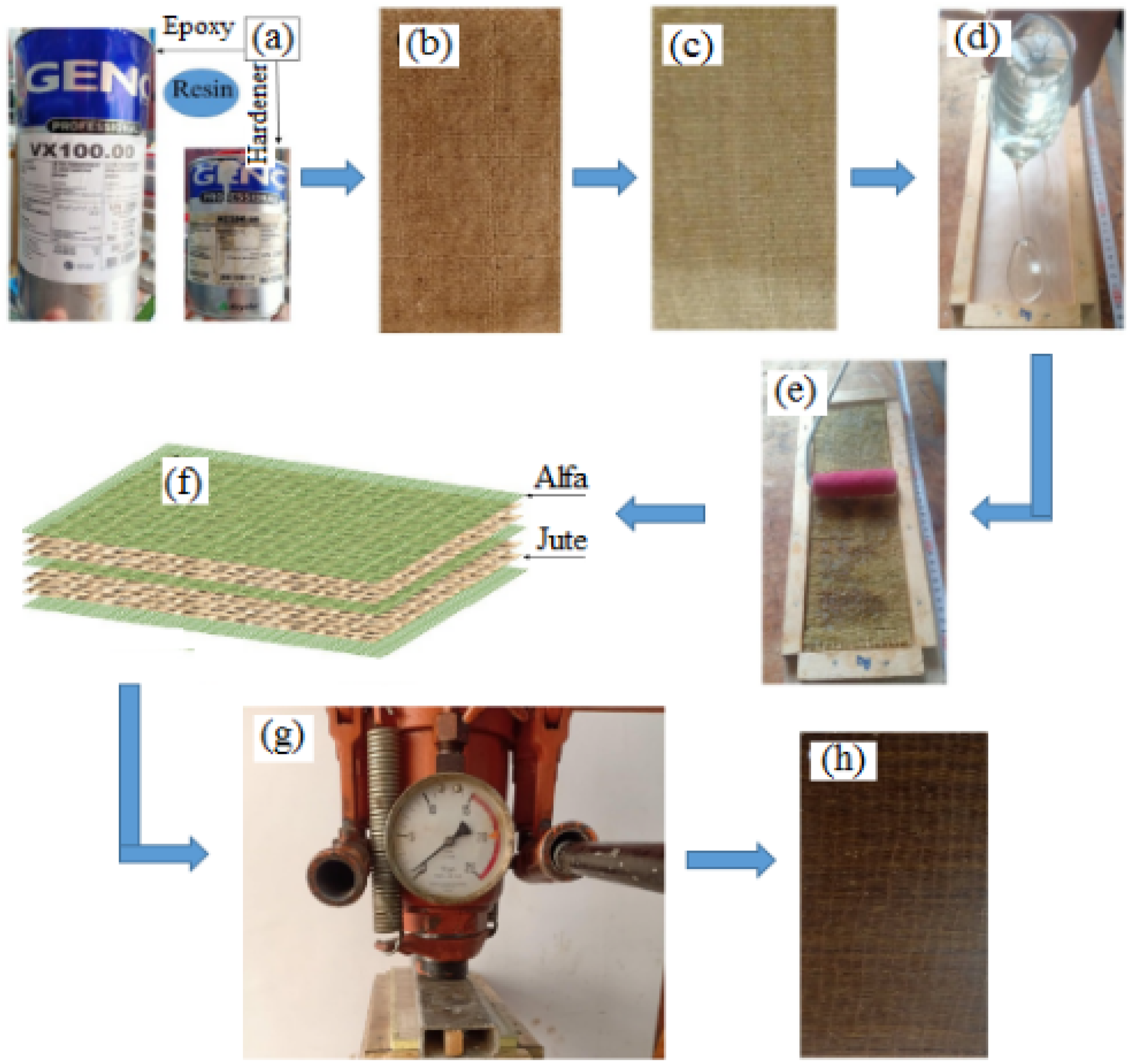
After curing, the final composite plate is demolded (Figure 1(h)). The dimensions of the resulting plate are 305 × 105 × 9 mm3.
Drilling experiment
The drilling tests were carried out using a three-axis vertical machining center, Quaser MV154 C, and the tests were conducted under dry cutting conditions with a variable spindle speed, capable of reaching up to 10,000 rpm (Figure 2a). The configuration of the plate during the drilling process is described in Figure 2(b). Three types of conventional helical drills with a diameter of 6 mm and different geometries were used. The point angles of Drill 1, Drill 2 and Drill 3 are 140°, 110° and 118°, respectively (Figure 2c). Experimental setup and device used during drilling on a CNC milling machine: (a) CNC milling machine, (b) Close-up of the force acquisition setup and (c) Drilling used in this work.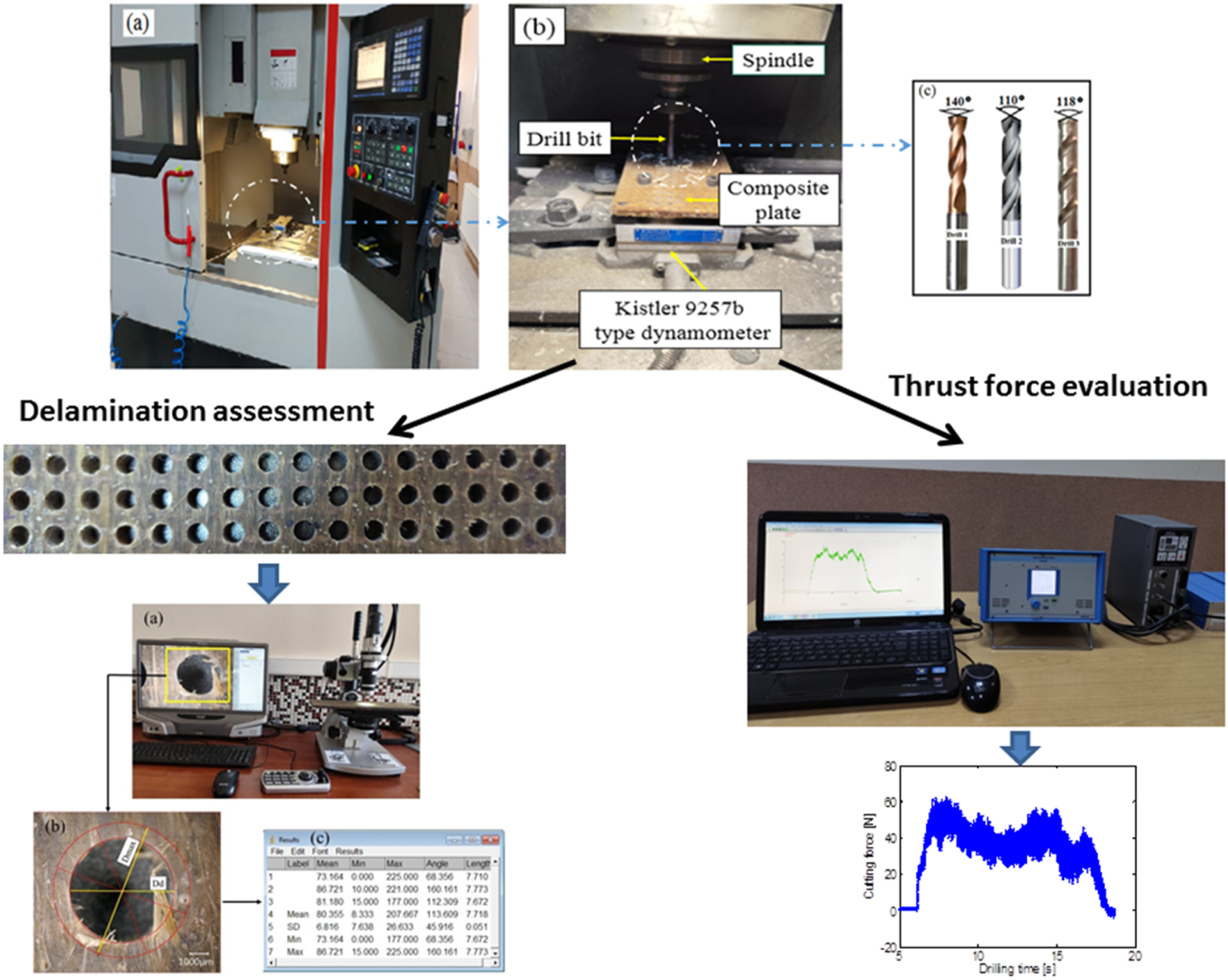
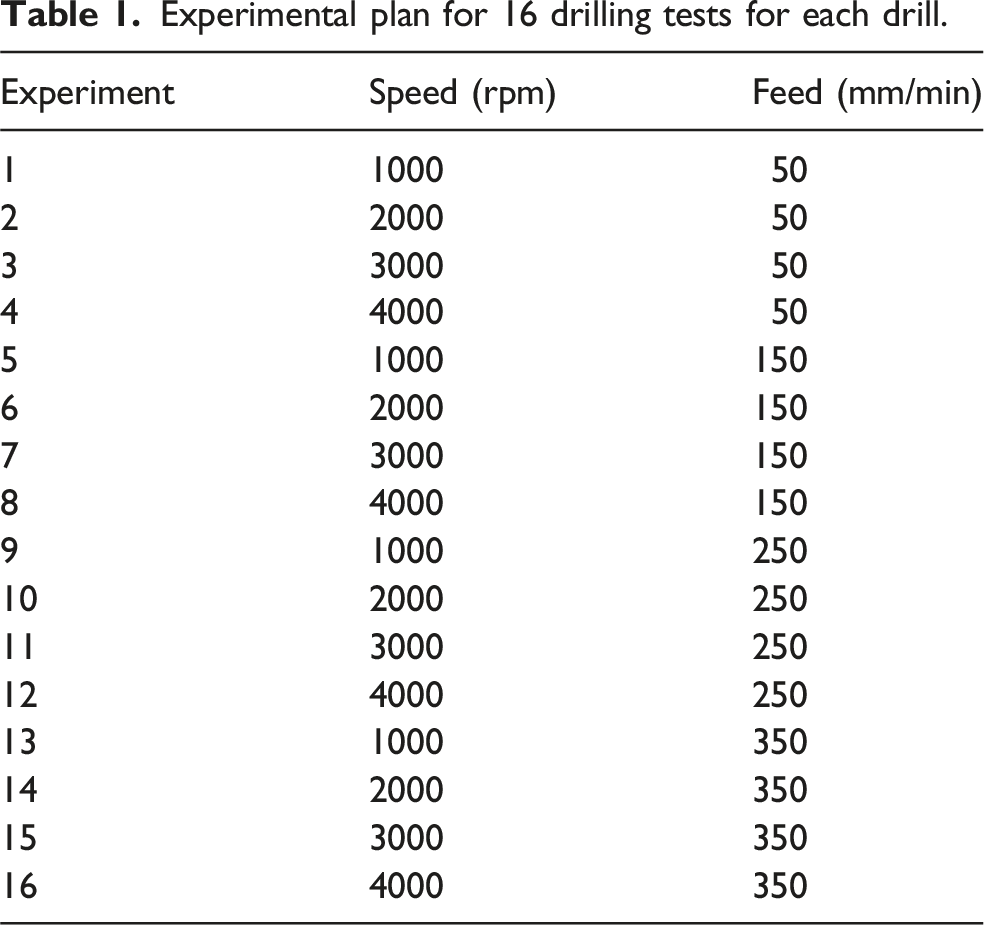
48 holes were drilled into the plate, with the first 16 using Drill D1, the next 16 using Drill D2 and the final 16 using Drill D3. The distribution and positioning of these drilled holes on the plate, as well as the drills used, are illustrated in Figure 3. The cutting parameters were selected based on an in-depth review of existing literature.47–50 The feed rate used during drilling ranged from 50 to 350 mm/min, and the spindle speed varied between 1000 and 4000 rpm. Table 1 provides a detailed overview of the cutting parameters used during the drilling of the plate for the three drills. Plate after drilling. Experimental plan for 16 drilling tests for each drill.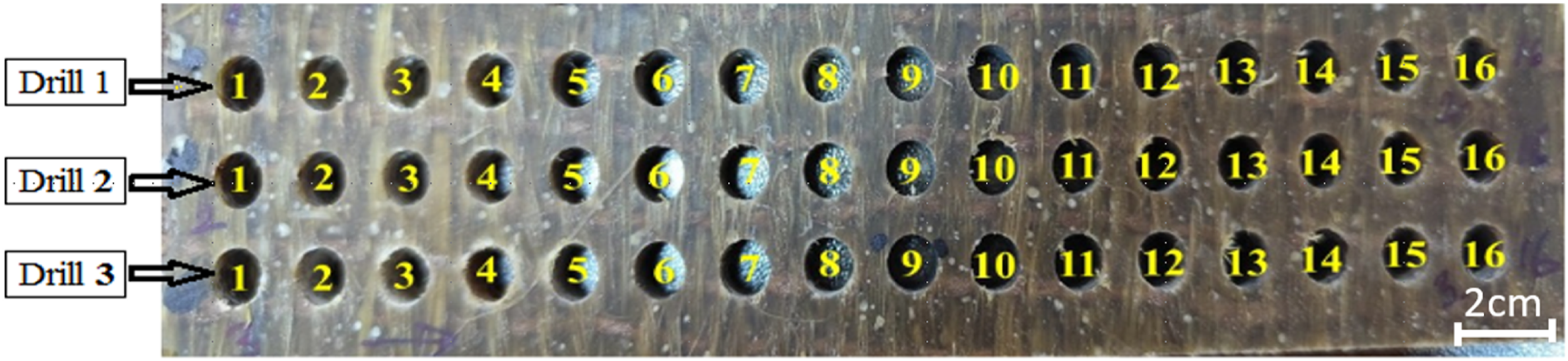
Thrust force measurement and delamination assessment
During the drilling experiments of the plate, the thrust force was measured using a Kistler dynamometer type 9257 B, a 5070 A charge amplifier, a 5697A data acquisition system and a PC, as shown in Figure 2(b). Delamination was observed on the surfaces of the holes, highlighting structural damage requiring thorough evaluation. Digital photographs were taken using a Keyence VHX-900 F digital microscope (Figure 4(a)) to document the areas affected by delamination, with a particular focus in this study on the exit side of the composite plate, as this area is prone to damage due to various factors related to the cutting process and the properties of the composite material. The delamination factor was selected as the primary indicator to characterize damage during the drilling of the hybrid composite. These images were then processed using Image J software, as illustrated in Figure 4(b). Measurement of the delamination factor: (a) Taken using the Keyence VHX-900 F microscope; (b) Representation of the drilling diameters: nominal and maximum; (c) Measured values of the maximum diameter using Image J.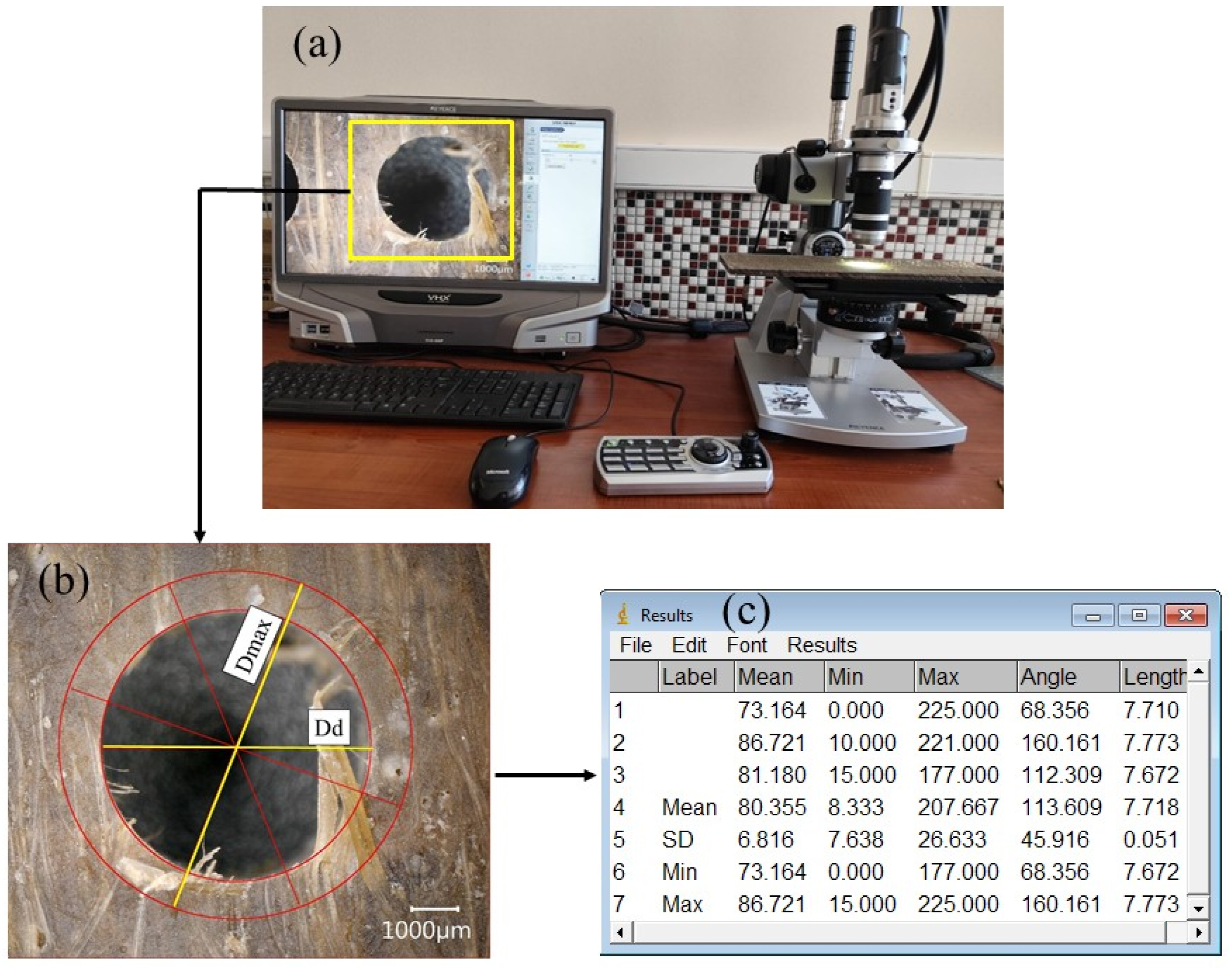
The calculation of the delamination factor was performed in accordance with well-established methods in the scientific literature.51,52 This factor is defined by the following standard mathematical formula: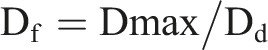
Results and discussions
Thrust force
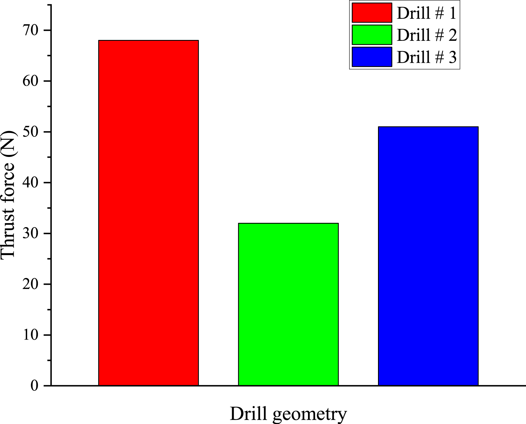
Figure 5 (a)–(d) shows the variation of thrust force as a function of feed rate at various spindle speed levels and with different drill point angle geometries. This graphical representation highlights the significant impact of feed rate on thrust force. An increase in feed rate leads to a noticeable rise in drilling thrust force. The trend of the curve profiles is almost linear. At a low feed rate (50 mm/min), thrust forces are the lowest, and the reduction with increasing spindle speed is significant for all drills. With a medium feed rate (150 mm/min), thrust forces increase moderately compared to 50 mm/min. For high feed rates (250 and 350 mm/min), thrust forces increase significantly, especially with drills D1 and D3. The thrust forces generated by drill D1 were higher than those obtained with drills D2 and D3. Drill D2 exhibited lower thrust force than drills D1 and D3 under all drilling conditions used. It is worth noting that the highest thrust force value (121.7 N) was observed for drill D1 at a feed rate of 350 mm/min and a spindle speed of 1000 rpm (Figure 5(a)), while the lowest thrust force value (17.88 N) was recorded with drill D2 at a feed rate of 50 mm/min and a spindle speed of 4000 rpm (Figure 5(d)). The analysis of the average thrust force from drilling tests for each drill, conducted under identical conditions, consistently confirms that drill D2 resulted in the lowest value (33.258 N), while drill D1 produced the highest value (65.003 N) (Figure 6). Previous studies35,40,53,54 have confirmed the general trend observed in our results. An increase in the drill point angle leads to a rise in thrust forces in all studied cases. This conclusion aligns with findings from previous studies on the drilling of other types of composite materials.55,56 The increase in feed rate leads to higher thrust forces during the drilling of the studied hybrid composite material due to several factors related to cutting dynamics and the specific properties of these materials. A higher feed rate means that the drill removes a greater amount of material per unit of time, requiring the tool to exert more force to cut and evacuate the material, thereby increasing thrust forces. Variation of thrust force as a function of feed rate and drills D1, D2 and D3. Average thrust force of drills D1, D2, and D3.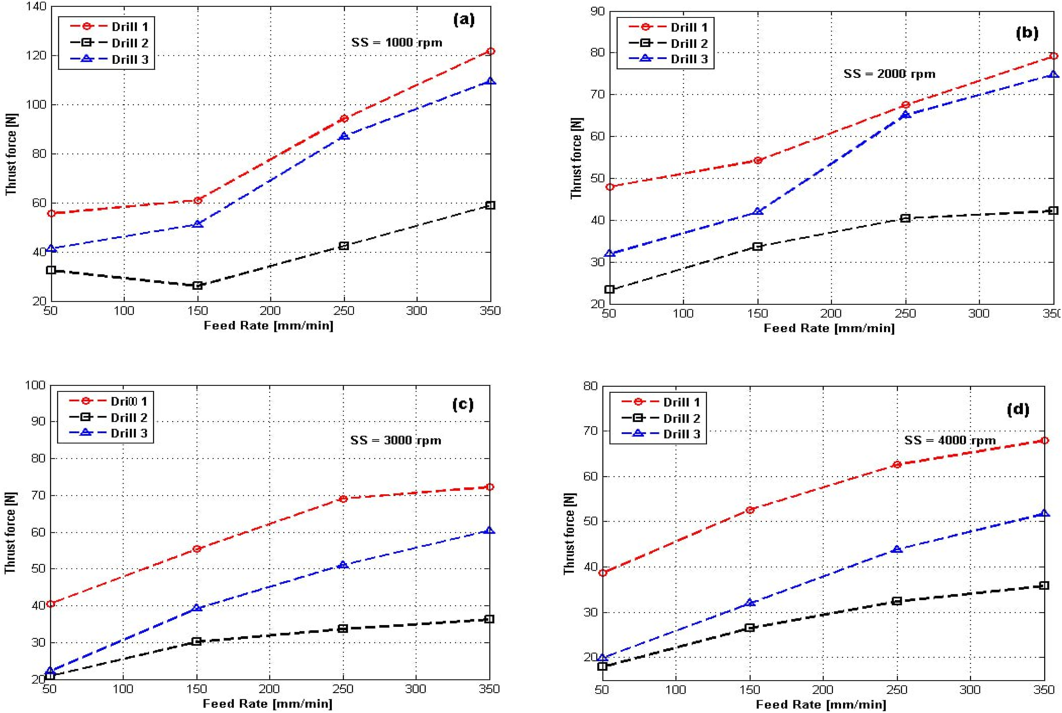
Moreover, this hybrid composite, composed of natural fibers (alfa and jute) and a polymer matrix, has a heterogeneous and anisotropic structure, making it sensitive to cutting forces. In other words, as the feed rate increases, the fibers and the matrix undergo more rapid and intense deformation before breaking, necessitating a greater thrust force to penetrate the material. A low point angle (110°) distributes cutting forces more effectively along the drill’s cutting edges, reducing localized stresses. In contrast, a larger point angle (118° and 140°) alters the distribution of forces during cutting. It increases the contact surface between the drill and the material, thereby raising resistance to penetration. As a result, a greater axial force is required to initiate and sustain the drilling process. Additionally, in the alfa-jute hybrid composite, which consists of natural fibers embedded in a polymer matrix, a larger point angle causes excessive fiber deformation before rupture, further increasing the thrust forces needed to drill through the material.
Figure 7(a)–(c) illustrates the variation of thrust force at four different spindle speed levels, various feed rates and for each drill geometry. Thrust force increased with the increase in drill point angle, whereas it decreased with the increase in spindle speed. The maximum thrust force values were observed for drill D1, while the minimum thrust force values were recorded for drill D2. The latter consistently generated the lowest thrust forces, followed by D3 and then D1. Specifically, at a spindle speed of 1000 rpm, drills D1, D2 and D3 recorded thrust forces of 55.58 N, 32.38 N and 41.26 N, respectively. At a spindle speed of 4000 rpm, the thrust forces recorded for drills D1, D2 and D3 were 38.60 N, 17.88 N and 19.84 N, respectively. However, thrust force varied only slightly with spindle speed in the range of 2000 rpm to 4000 rpm for each corresponding feed rate with drills D1 and D3. It had no significant influence with drill D2, where the difference between the highest and lowest values generally did not exceed 8 N. A high spindle speed (4000 rpm) helps reduce thrust force regardless of the drill type. These results are consistent with trends observed in other research studies.35,57 Variation of thrust force as a function of spindle speed, various feed rates and drills D1, D2, and D3.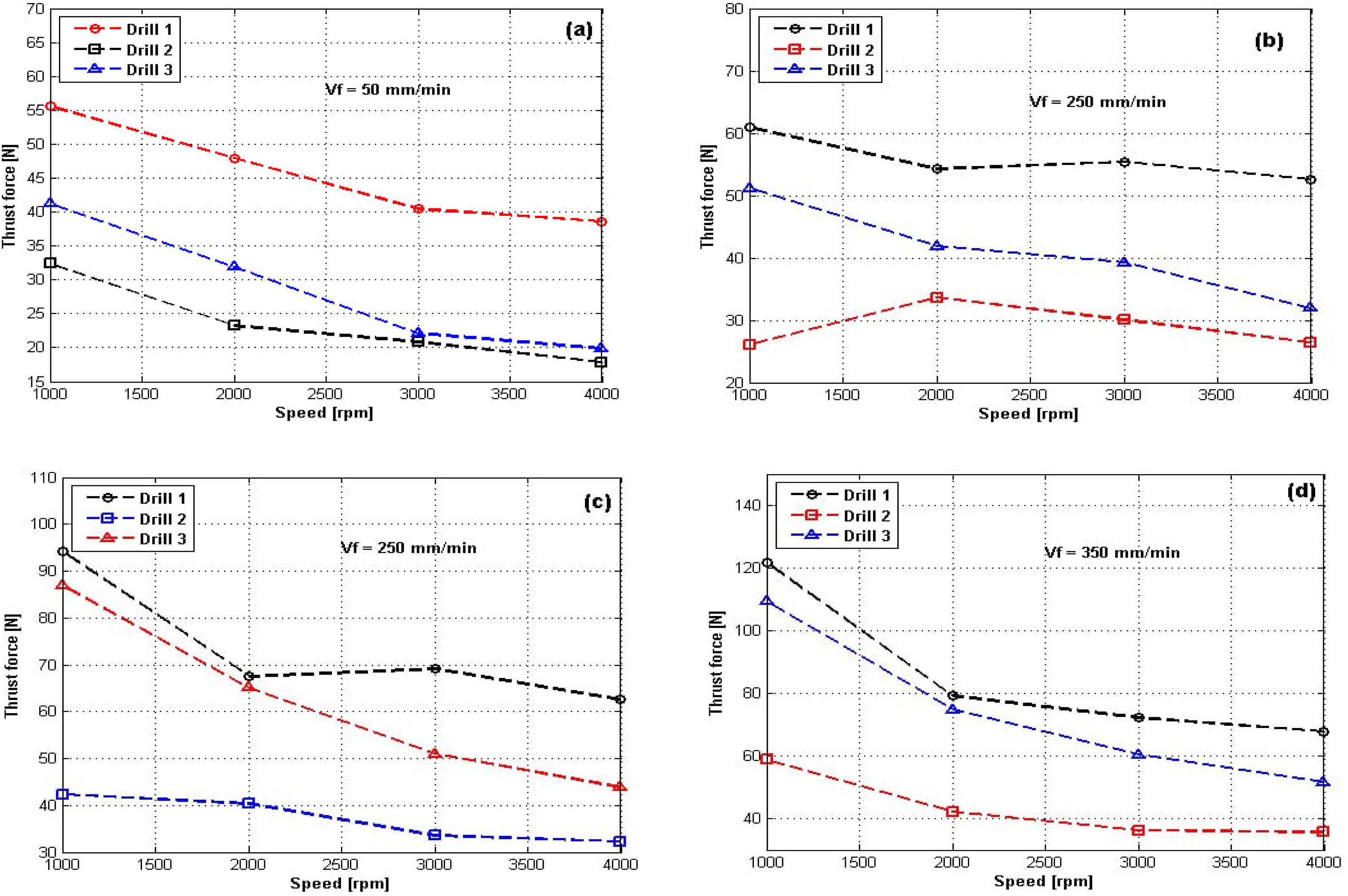
Delamination
The average delamination factors at the hole exit depend on the feed rate and the drill point angle at constant spindle speeds. Figure 8 illustrates the influence of feed rate on the delamination factor (Fd) for the three drills. The delamination factor (Fd) increased with feed rate, regardless of the drill type. The Fd values for drill D1 were higher than those for drills D2 and D3. The delamination factor (Fd) for drill D3 was intermediate between D1 and D2, following a similar trend to drill D1. The increase in Fd with feed rate for drill D2 was less pronounced compared to drills D1 and D3. Specifically, at a feed rate of 350 mm/min and a spindle speed of 4000 rpm, Fd reached 1.149, which was significantly lower than that of drills D1 and D3. Lower delamination factor values were observed with drill D2, which produced a minimum Fd value of 1.0491 at a feed rate of 50 mm/min and a spindle speed of 1000 rpm. In contrast, the highest Fd value (1.2973) was recorded for drill D1 at a feed rate of 350 mm/min and a spindle speed of 3000 rpm. Elhadi et al,
49
as well as Krishna et al
27
found that the delamination factor increases with the increase in feed rate. The increase in the point angle also leads to an increase in delamination, regardless of the drill type, according to Shah et al,
1
this is consistent with our results. An increase in feed rate leads to significant delamination due to mechanical stresses and the reduced time for a clean and controlled cut.
58
At high speed, the tool quickly penetrates the material and exerts high thrust forces, causing excessive material deformation, particularly at the fiber-matrix interface, which is often the weakest point of composites. Moreover, a high feed rate reduces the contact time between the tool and the material, potentially decreasing the efficiency of cutting mechanisms. Instead of a clean cut, the fibers and matrix may be torn or crushed, leading to defects such as delamination. This delamination is even more pronounced near the drill exit, where the material becomes less structurally supported and is more likely to separate due to thrust forces and crack propagation.
59
Variation of the delamination factor as a function of feed rate and Drills D1, D2 and D3.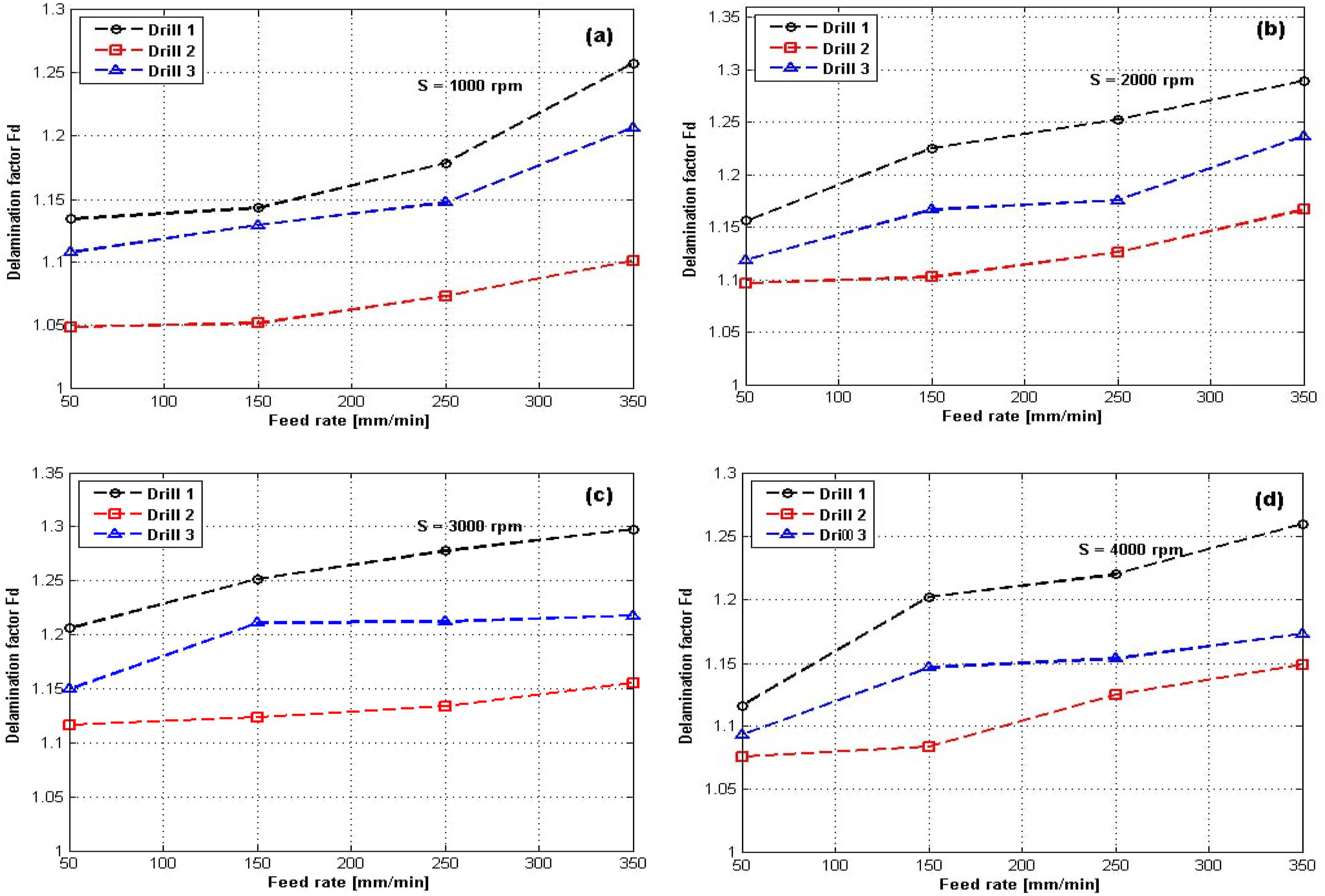
Increasing the drill point angle leads to greater delamination due to mechanical and thermal factors related to the drill geometry and the behavior of the composite material used. With a higher point angle, the central zone of the drill becomes wider. This zone exerts increased axial pressure on the material without performing effective cutting, resulting in significant compression of the fibers and polymer matrix before the cutting edges engage. This excessive compression promotes the separation of composite layers, increasing the risk of delamination, particularly at the drill exit where the layers are less supported. Additionally, a high point angle distributes forces over a narrower area near the drill’s central axis, concentrating mechanical stresses in this region. This requires applying a higher axial force to penetrate the material, further increasing the risk of composite layer separation. The increase in point angle also expands the contact surface and friction between the drill and the material, generating more heat. This heat can soften the polymer matrix, reducing its ability to hold the fibers together, which further promotes delamination. To minimize this phenomenon, it is recommended to use a smaller point angle (110°) and optimize other drilling parameters, such as feed rate and spindle speed.
The combination of the results presented in Figures 5 and 8 clearly highlights a general trend: as the thrust force increases, the delamination factor also increases. This correlation reflects a well-documented phenomenon in the machining of composite materials, particularly during the drilling of fiber-reinforced laminates.
When the drill bit penetrates a composite laminate, it generates a downward axial force. If this thrust force becomes too high, it leads to an accumulation of mechanical energy within the internal layers of the material. This stored energy becomes critical near the exit side of the drill, where the structure is most vulnerable. At this point, the material is subjected to high tensile stresses perpendicular to the laminate plane. If the mechanical energy exceeds the interlaminar strength of the composite that is, the strength of adhesion between the fiber layers and the matrix it results in the formation of cracks or separation between plies, a phenomenon known as delamination.
The thrust force is thus a key factor in limiting delamination, which in turn ensures the structural, functional and dimensional quality of drilled holes in composite materials. A deep understanding of this relationship enables improved mechanical performance of finished parts, as well as reduced manufacturing defects and costs in industrial applications.
Figure 9 illustrates the influence of spindle speed and drill type (D1, D2 and D3) on the delamination factor. The results showed that spindle speed has a significant impact on the delamination factor (Fd) during the drilling of the jute-alfa hybrid composite material. An increase in delamination is observed at moderate spindle speeds (1000 rpm to 3000 rpm), followed by a decrease at high speed (4000 rpm). For drill D1, the delamination factor Fd generally increases with spindle speed, rising from 1.1344 at 1000 rpm to 1.2068 at 3000 rpm before slightly decreasing at 4000 rpm (1.1163). However, at high speeds (2000–3000 rpm), Fd reaches higher values, such as 1.2774 at 3000 rpm, indicating worsening delamination. For drill D2, Fd remains generally lower than for drill D1, with values ranging between 1.0491 (1000 rpm) and 1.1666 (2000 rpm), demonstrating better performance in reducing delamination. Drill D3 shows intermediate results, with Fd varying from 1.108 (1000 rpm) to 1.2368 (2000 rpm), but also exhibiting a tendency for increased delamination at high speeds. Influence of spindle speed on the delamination factor for the three drills.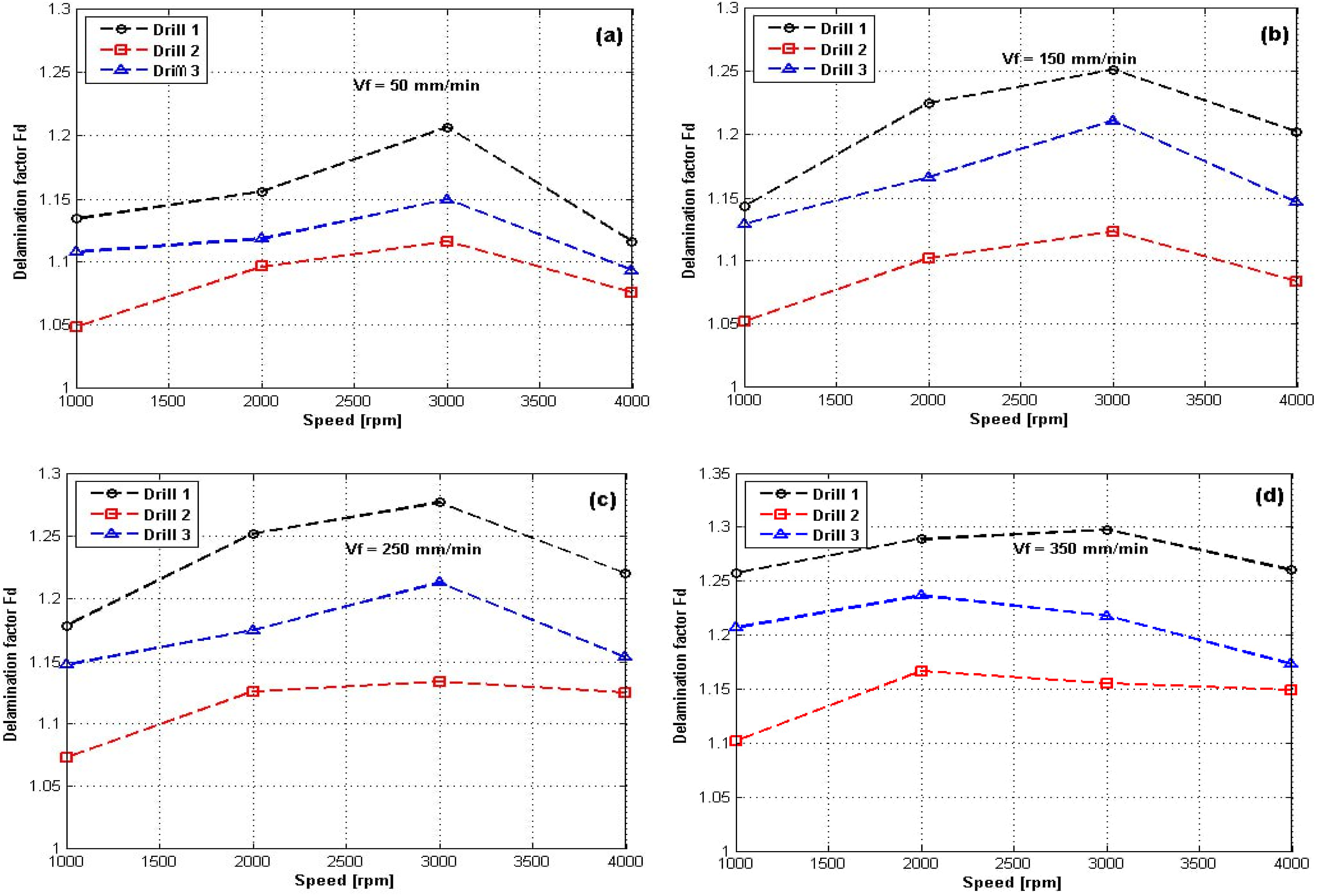
The increase in delamination at spindle speeds between 1000 rpm and 3000 rpm, followed by a decrease at higher speeds (4000 rpm), can be explained by several interrelated mechanisms. At moderate speeds, cutting forces increase with spindle speed, exerting greater pressure on the fiber and matrix layers, leading to layer separation (delamination). Additionally, natural alfa and jute fibers are less rigid than synthetic fibers, undergoing excessive deformation before breaking, creating additional stress between the material layers. Furthermore, localized heating increases with speed, softening the polymer matrix and reducing its ability to maintain cohesion between layers, which worsens delamination.
However, at higher speeds (4000 rpm), delamination decreases due to improved chip evacuation, which reduces obstruction and friction in the cutting zone. Moreover, a higher spindle speed enables faster and cleaner fiber cutting, limiting their deformation and reducing thrust forces. Finally, the dynamic effect of high-speed cutting makes the process more efficient, thereby reducing the risk of delamination.
During the drilling of composite materials, delamination mainly occurs at the drill entry and exit points. Entry delamination results from the initial contact between the drill and the composite surface, while exit delamination occurs when the drill fully penetrates the material. These phenomena can lead to hole diameter enlargement and structural degradation of the composite.
In this study, exit delamination was analyzed in relation to hole quality. In hybrid natural fiber composites, delamination is strongly influenced by spindle speed, feed rate and the type of drill used. Increasing the spindle speed significantly reduced the average delamination factor and contribute to improving the quality of drilled holes. However, at higher feed rates, delamination is more likely to occur. 35 This suggests that higher feed rates generate greater forces and vibrations, which in turn lead to increased delamination. The study by Yalçın et al. 60 focused on optimizing dry drilling of glass fiber-reinforced epoxy composites used in aerospace structures. The research examined the effects of spindle speed (1000, 2250, 4000 and 5750 rpm) and feed rate (0.2, 0.4, 0.6 and 0.8 mm/rev) on thrust force and delamination. The study identified that medium spindle speeds (2250–4000 rpm) and a low feed rate (0.2 mm/rev) provided optimal conditions for minimizing thrust force and delamination. Gemi et al. 26 investigated the effect of drill type on the drilling performance of glass fiber reinforced plastic composite tubes. The drilling tests were conducted with different types of drills (conventional twist drill, point drill, and center drill) with a diameter of 4 mm at a constant spindle speed of 5000 rpm and six different feed settings (25, 75, 125, 175, 225 and 275 mm/min). The results showed that the thrust force increases as the feed rate increases. The point center drill produces lower thrust forces, while the twist drill produces higher ones. The severity of damage may vary depending on the tool geometry and feed rate. In particular, at lower feed rates, the conventional twist drill exhibits greater delamination and uncut fibers than other drills. Additionally, the incorporation of carbon nano onions (CNOs) into polymer composites has been shown to significantly reduce cutting force and surface roughness during drilling.61,62 The optimum CNO content of 1.5 wt% improved hole quality by minimizing crack formation and machining-induced damage, highlighting the potential of nanoparticle-reinforced composites to enhance drilling performance. 61
Figure 10 shows the holes resulting from drilling with drill D2 at different feed rates (50, 150, 250 and 350 mm/min) while maintaining a constant spindle speed of 1000 rpm. This figure qualitatively illustrates delamination damage through images of selected holes subjected to various drilling conditions. Small defects, such as burr formation, uncut fibers, and damage around the hole perimeter, were observed. At a 50 mm/min feed rate, the hole edges exhibit a small amount of torn fibers, uncut fibers and yarns and debris around the drilling zone. These debris and torn fibers are characteristic of delamination, often observed at low feed rates, where the tool applies prolonged pressure on the material layers without rapid progression. At a 150 mm/min feed rate, the hole edges are slightly cleaner and better defined compared to the previous case, although some debris remains visible around the hole but in reduced amounts. The delamination factor remains nearly the same, but the drilling quality has slightly improved. At 250 mm/min, the hole edges become more uniform and well-defined, with less visible debris and fewer signs of torn fibers. The slight increase in the Fd factor may be attributed to internal damage. At 350 mm/min, the edges remain relatively uniform, but irregularities reappear around the hole, likely due to the higher feed rate. The increase in the Fd factor suggests that internal damage or deformations may occur at this speed. Damages to the hole caused by drill D2 (SS = 1000 rpm).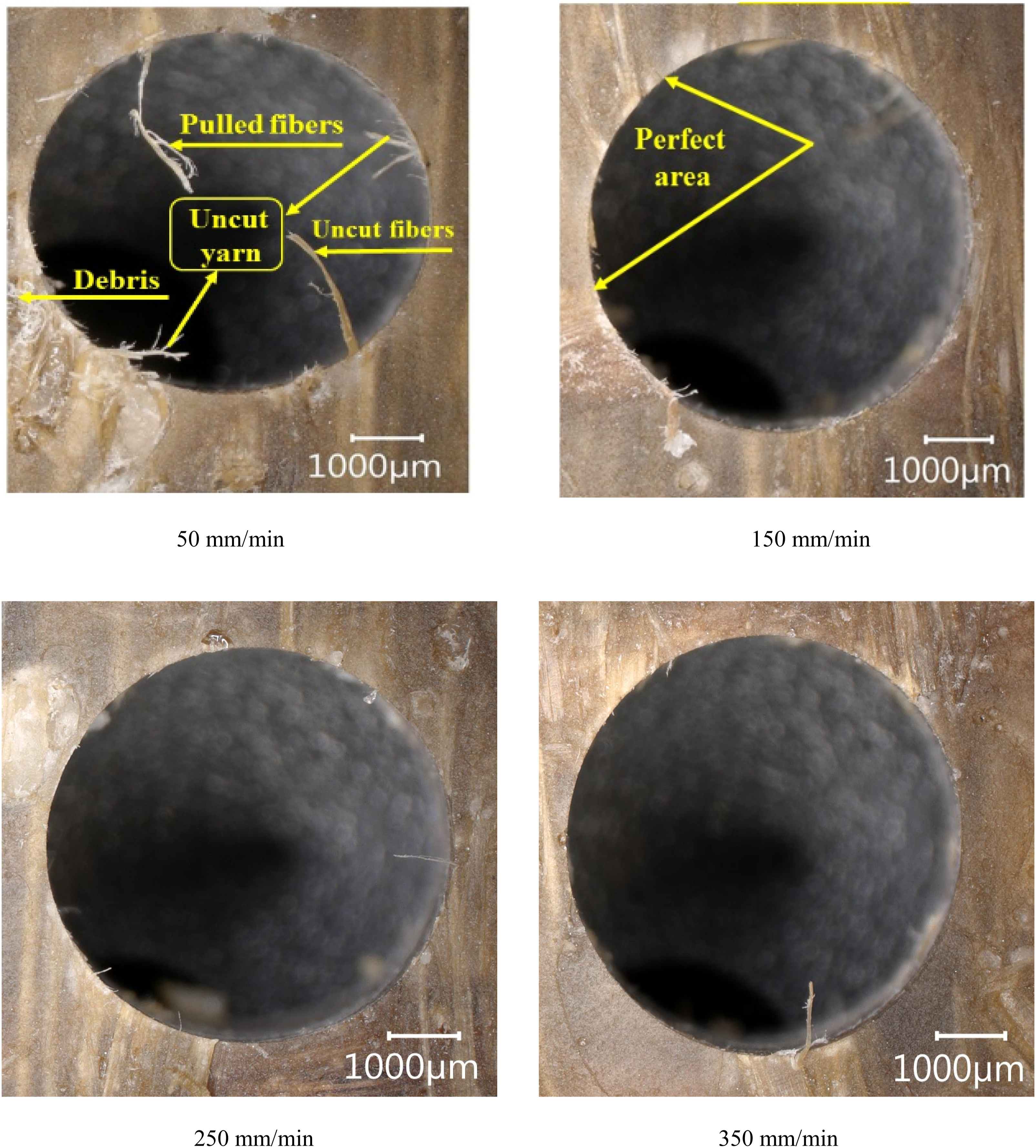
Figure 11 shows the holes resulting from drilling with drill D2 at different feed rates (50, 150, 250 and 350 mm/min) and a spindle speed of 4000 rpm. The images illustrate uncut and torn fibers around the hole perimeter, indicating a delamination phenomenon. The presence of burrs suggests that machining has generated excessive forces on the composite layers. At the lowest feed rate (50 mm/min), minimal damage is expected, whereas at the highest feed rate (350 mm/min), the most pronounced defects are likely observed. This is consistent with increased thrust forces causing greater separation of the interfacial layers. This visual trend reinforces the quantitative relationship between feed rate and delamination severity, highlighting the need to find a balance in machining parameters to minimize material damage. Damages to the hole caused by drill D2 (SS = 4000 rpm).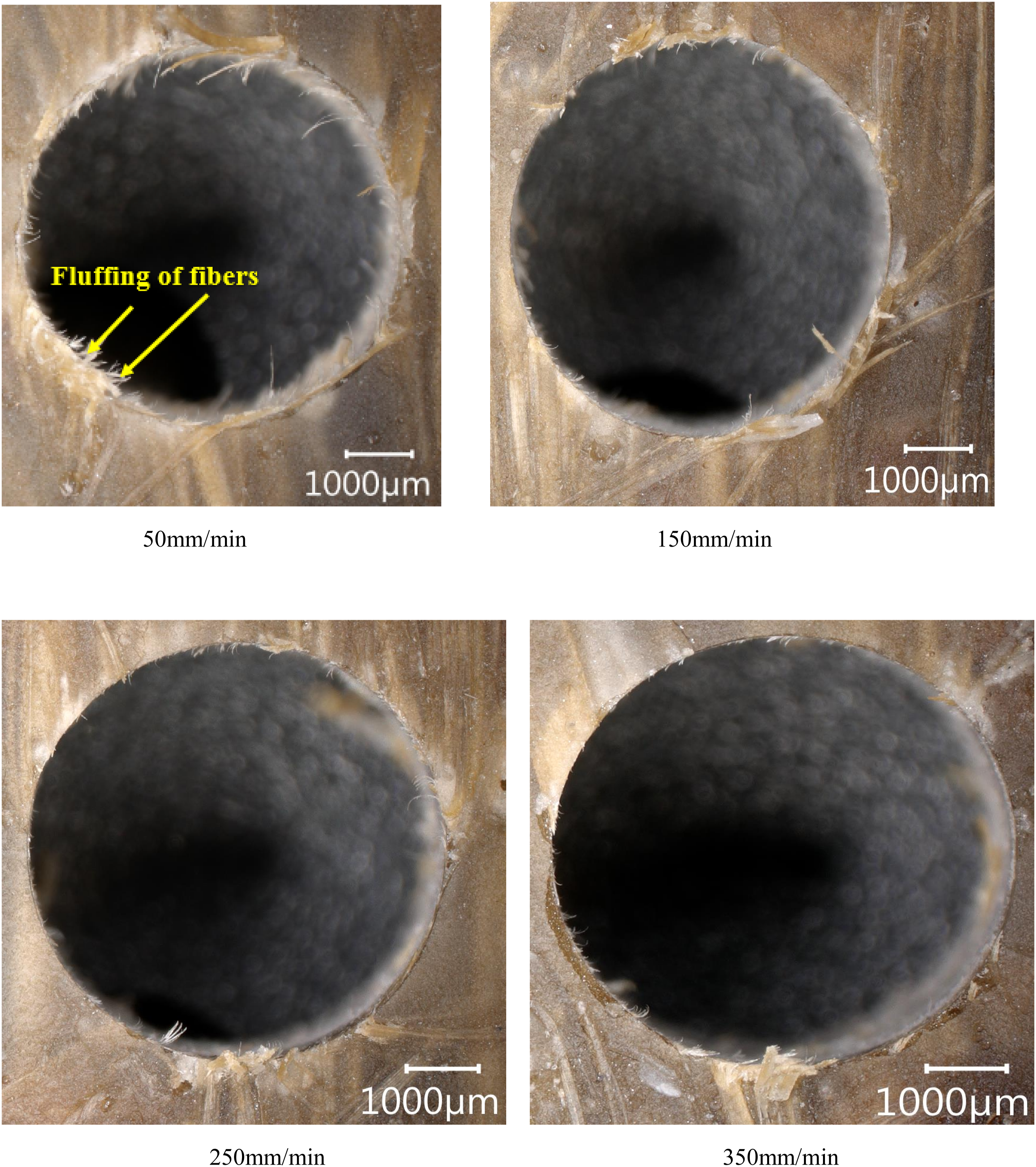
Figures 12 and 13 illustrate the holes obtained during drilling with drills D1 (point angle 140°) and D3 (point angle 118°), respectively, using different feed rates (50, 150, 250 and 350 mm/min) while maintaining a constant spindle speed of 1000 rpm. The images show fiber tearing around the holes, indicating significant mechanical stress during drilling. Jute and alfa fibers appear to detach in lamellae and fragments, suggesting weak local cohesion within the composite matrix. The presence of long fibers extending around the hole perimeter indicates that some fibers were not properly cut. The hole edges exhibit irregularities and fiber chipping, indicating poor surface quality. Damages to the hole caused by drill D1 (SS = 1000 rpm). Damages to the hole caused by drill D3 (SS = 1000 rpm).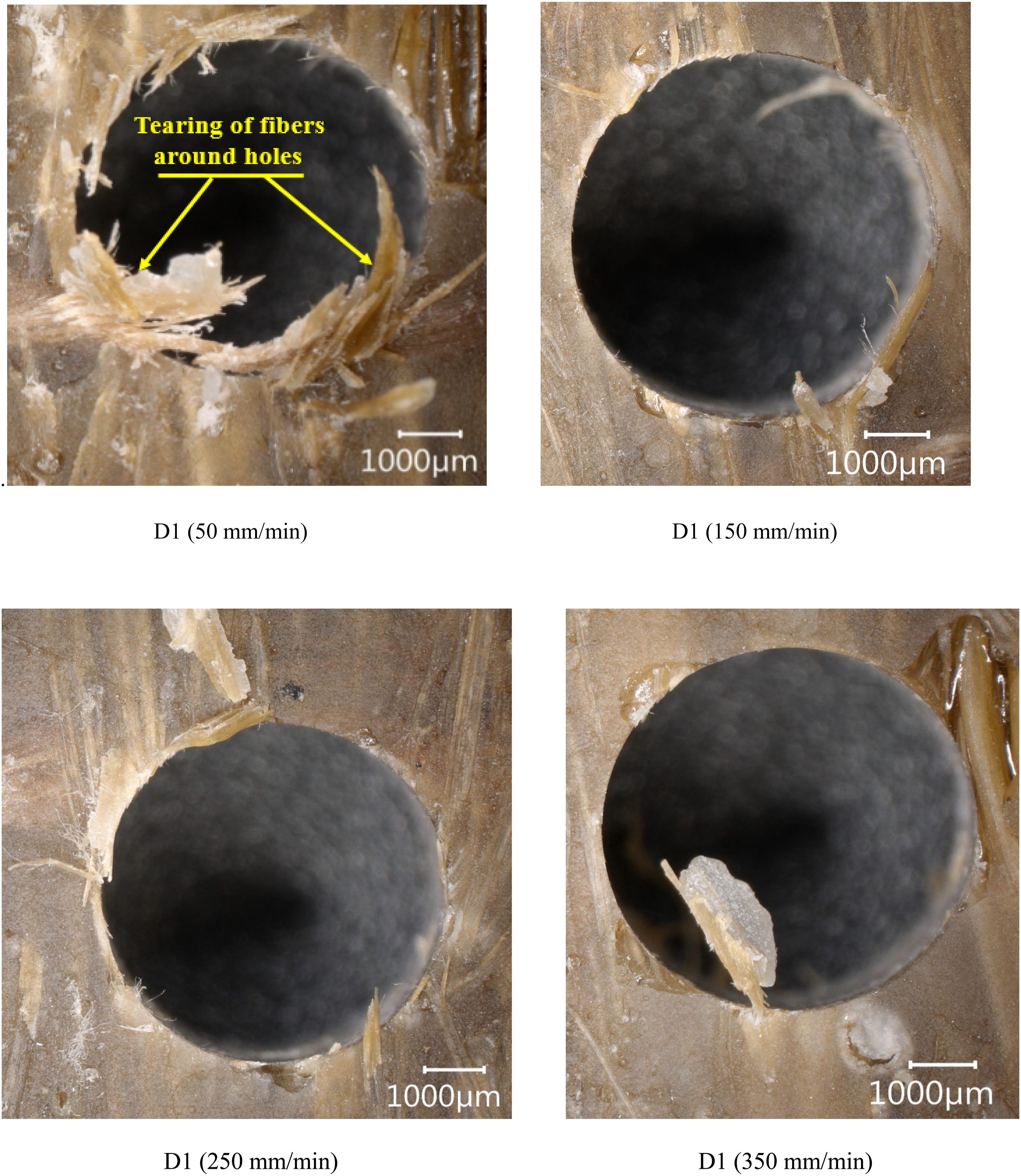

Figure 14 shows the holes obtained during drilling performed with drills D1 (140° point angle) and D3 (118° point angle), considering both a low feed rate of 50 mm/min and a high feed rate of 350 mm/min, while maintaining a constant spindle speed of 4000 rpm. The images of holes drilled at a low feed rate (50 mm/min) revealed partially detached fibers that appear bent or torn, more pronounced frayed fibers, and, in some areas, long visible fragments with irregular hole edges. At the higher feed rate of 350 mm/min, some fraying was observed, but there were fewer torn or residual fibers. The hole quality was slightly irregular, with signs of delamination. Defects such as fiber fraying, the presence of long uncut fibers, irregularities, and burrs around the hole perimeter are not solely linked to high feed and spindle speeds. They also appear at lower speeds, regardless of the drill type used. Damages to the hole caused by drill D3 (SS = 4000 rpm).
However, drill D2 (110°) exhibited a lower occurrence of these defects, achieving an acceptable drilling quality in 62% of cases, followed by drill D3 with 37%, while drill D1 showed the lowest performance with a rate of 25%.
Three-way ANOVA of the full factorial design (3 drills × 4 speeds × 4 feeds) revealed significant effects on thrust force and delamination. For thrust force, drill geometry showed the strongest effect (F (2,32) = 87.3, p < 0.001, η2 = 0.62), followed by feed rate (F (3,32) = 45.1, p < 0.001, η2 = 0.23) and speed (F (3,32) = 6.8, p = 0.003, η2 = 0.07). A significant drill × feed interaction (F (6,32) = 3.8, p = 0.012) indicated geometry-dependent force responses to feed changes.
For delamination factor (Fd), feed rate dominated (F (3,32) = 92.4, p < 0.001, η2 = 0.59), with drill geometry (F (2,32) = 9.1, p = 0.002, η2 = 0.17) and a drill × speed interaction (F (6,32) = 2.9, p = 0.038) also significant. Post-hoc Tukey tests confirmed D2 (110°) reduced forces by 21.4% versus D1/D3 (p < 0.01), while feeds ≤200 mm/min maintained Fd < 1.15 (p = 0.003). Assumptions were validated (Shapiro-Wilk p > 0.15; Levene’s p > 0.20).
To mitigate potential concerns related to tool wear during drilling, several precautions were integrated into the experimental design. Firstly, the natural fiber reinforcements used in this study (jute and Alfa) are known for their low abrasiveness compared to synthetic fibers, which minimizes the risk of tool degradation, as supported by previous research.15,53 Secondly, each drill bit (D1–D3) was limited to drilling only 16 holes, remaining well below the typical threshold at which wear becomes significant in similar materials. 53 Additionally, a randomized drilling sequence was employed to eliminate systematic wear effects. Visual inspection of the drill edges after experimentation revealed no detectable flank wear or edge chipping.
Conclusion
This study highlights an in-depth analysis of the cutting parameters and drill point angle influencing the thrust force and delamination during the drilling of a Jute-Alfa/Epoxy hybrid composite. The main conclusions drawn from this study are:
Drilling performance insights
Feed rate and thrust force: Increasing the feed rate leads to a rise in thrust force. At a reduced feed rate of 50 mm/min, the thrust force is lower and gradually increases with higher feed rates.
Spindle speed effects: A high spindle speed of 4000 rpm helps reduce the thrust force, regardless of the drill used. The spindle speed range between 2000 and 4000 rpm has a moderate impact on thrust force, particularly for drill D2.
Drill geometry influence
Drill D2 (110° point angle): Performs better in reducing thrust force and distributing cutting forces.
Drill D1 (140°) and Drill D3 (118°): These increase penetration resistances and require higher axial force.
Material characteristics: The heterogeneous and anisotropic structure of the Jute-Alfa/Epoxy hybrid composite influences the thrust force, making it more sensitive to cutting forces.
Delamination and hole quality
Feed rate and delamination: The delamination factor (Fd) increases with the feed rate, regardless of the drill used.
Drill D2 Performance: Drill D2 systematically generates the lowest Fd values, promoting cleaner cuts and indicating better performance in delamination reduction, especially at high speeds.
Spindle speed and delamination: At moderate speeds (1000–3000 rpm), delamination increases due to cutting forces and local heating. However, at a high speed of 4000 rpm, delamination decreases due to better chip evacuation and cleaner cutting.
Feed rate and surface defects: A clear relationship is established between increased feed rate and damage such as uncut fibers, burrs, and delamination around the holes.
Drill geometry and defects
Drill D2 (110°): Exhibited minimal defects at low speeds and generally provided better drilling quality.
Drills D1 (140°) and D3 (118°): Showed more pronounced fiber tearing, indicating higher mechanical stress.
These findings highlight the importance of selecting appropriate drilling parameters and tool geometries to optimize hole quality and minimize damage in Jute-Alfa/Epoxy hybrid composites.
Footnotes
Funding
The authors received no financial support for the research, authorship, and/or publication of this article.
Declaration of conflicting interests
The authors declared no potential conflicts of interest with respect to the research, authorship, and/or publication of this article.
Data Availability Statement
The datasets generated and analyzed during the current study are available from the corresponding author on reasonable request.