
Abstract
To investigate the wind-blown sand erosion resistance of Carbon Fiber Reinforced Polymer (CFRP) laminates, this study conducted simulated wind-blown sand erosion experiments using erosion velocity as a variable and tested the mechanical properties of the materials after erosion. Meanwhile, Furthermore, a VUMAT subroutine integrating the Discrete Element Method (DEM) with the 3D-Hashin criterion was developed in ABAQUS. This approach aims to establish a quantitative relationship between stochastic multi-particle erosion and the anisotropic micro-damage of CFRP laminate, thereby overcoming the limitations of traditional methods in quantifying erosion mechanisms. The model was first validated for accuracy using experimental results obtained at different erosion velocities. Subsequently, to further examine the model’s generalizability and prediction accuracy, supplementary experiments under different sand flow rates were conducted, and the simulation results were compared with the measured data. The results indicate that during the validation phase (different erosion velocities), the relative errors between the simulated and experimental values for the tensile strength and elastic modulus of CFRP laminate were 1.37%–4.18% and 3.56%–6.48%, respectively; whereas during the prediction validation phase (different sand flow rates), these relative error ranges were 0.83%–6.53% and 0.44%–1.4%, respectively. These results not only validate the model’s accuracy but also demonstrate its robust predictive potential for untested scenarios. The model can reliably simulate the mechanical degradation and damage evolution of CFRP laminate under real-world wind-blown sand environments, thereby providing an effective numerical tool for the durability assessment of CFRP structures.
Introduction
Carbon Fiber Reinforced Polymer (CFRP) is a high-performance material consisting of fibers embedded in a resin matrix, characterized by excellent properties such as high tensile strength, lightweight, durability, and corrosion resistance. CFRP can significantly enhance the durability of concrete structures in harsh environments and extend their service life; consequently, it has been widely applied in engineering practices1,2 However, when such structures are situated in wind-sand environments, the continuous impact of high-velocity sand particles on the CFRP surface causes surface damage, significantly reducing the load-bearing capacity and service life of the material. Due to the instantaneous and violent nature of the erosion process, along with complex damage modes, it is difficult to reveal the continuous mechanism from particle impact to material failure relying solely on experimental observations3,4 Therefore, a deep understanding of the damage mechanism of CFRP under wind-blown sand erosion, along with the establishment of effective simulation and prediction methods, is of great significance for ensuring structural safety and stability as well as extending service life5,6
Laboratory particle erosion testing serves as a primary method for simulating the process of high-velocity particle flows impacting material surfaces. Based on the acceleration mechanisms, these tests are categorized into jet, rotary, and centrifugal erosion7,8 with jet erosion being the most widely applied. The principle involves utilizing high-pressure gas to accelerate abrasive particles through either a Laval nozzle9,10 or a straight pipe nozzle, generating a high-velocity jet to impinge upon the target material. Owing to its advantages—such as high particle velocity, controllable impact direction, and adjustable flow rate—this method has established itself as a standard approach for investigating erosion mechanisms and comparing material performance. In light of this, this study adopts the jet erosion method to conduct wind-blown sand erosion experiments.
Existing research indicates that erosion outcomes are influenced by erosion conditions, target material properties, and particle characteristics, among which erosion conditions exert the most significant influence. Choudhary et al. 11 discovered that erosion velocity governs the failure mode; specifically, FRP predominantly exhibits delamination cracking under low-velocity erosion, whereas penetration is likely to occur under high-velocity conditions. Regarding impact angle, the erosion rate of ductile materials initially increases and then decreases with increasing angle (peaking at 15°–30°), while that of brittle materials increases with the angle (peaking near 90°)12,13 In contrast, the maximum erosion rate for semi-ductile FRP occurs at 45°–60°. 14 In terms of particle parameters, Chellaganesh et al. 15 noted that the contribution of particle flux to the erosion rate can reach up to 20%. Arnold et al. 16 further observed that under low-flow conditions, the erosion rate increases as the flow rate decreases, a phenomenon attributed to inter-particle interactions. 17 Furthermore, scholars have proposed the concept of a “critical particle size”, 18 suggesting that the erosion rate remains constant once the particle size exceeds a certain threshold. Zhang et al. 19 indicated that, at a constant concentration, an increase in particle size reduces the number of particles, thereby lowering the impact probability. However, for FRP materials characterized by significant anisotropy and multiphase structures, the erosion response mechanism exhibits more complex features. On the one hand, the behavior at the fiber-matrix interface undergoes nonlinear evolution under impact 20 ; on the other hand, the voids and weaving paths inherent in the fiber weave structure further enhance the non-uniformity and directionality of damage development. 21 Consequently, traditional erosion models based on the assumption of homogeneous materials struggle to accurately describe the damage evolution patterns of FRP materials in sandstorm environments20,22
Although the aforementioned experimental studies have revealed macroscopic laws, limitations persist in capturing microscopic mechanisms and conducting parametric analysis. Currently, research on the erosion resistance of CFRP relies primarily on methods such as sand blasting and wind tunnel tests23–25 While these methods can provide macroscopic damage data, they are often costly and time-consuming. Furthermore, they face difficulties in capturing the microscopic evolutionary process at the instant of particle impact in real time. In terms of numerical simulation, the conventional Finite Element Method (FEM) faces significant limitations in handling the complex interactions between numerous discrete particles and continuous media. 26 Although meshless methods such as Smoothed Particle Hydrodynamics (SPH) have been applied to simulate material damage, their applicability to large-scale particle impact problems remains to be verified27,28 Furthermore, although scholars have investigated the influence of various failure criteria—such as Puck, Hashin, and Chang-Chang—on the dynamic progressive failure behavior of CFRP laminate29–32 there is a notable scarcity of research that combines efficient particle generation algorithms with refined damage models. Although the general-purpose finite element software ABAQUS is widely applied in structural analysis33,34 the application of its built-in particle generator module remains underexplored regarding the simulation of realistic wind-sand flow fields and the refined damage mechanisms of composites under particle impact. While the FEM provides an effective means to characterize the erosion process, 35 existing models predominantly rely on simplified material removal criteria or empirical erosion functions, failing to simultaneously capture the anisotropic characteristics of the material and the progressive accumulation of erosion damage36,37 Furthermore, current erosion simulation studies primarily concentrate on metallic materials or adopt simplified impact models38–40 Research that specifically addresses the anisotropic nature of CFRP by utilizing a particle generator to simulate random impacts coupled with complex damage models remains particularly scarce.
To address the aforementioned issues, this paper proposes a numerical simulation method based on the ABAQUS platform and its particle emitter module to efficiently and accurately simulate the erosion damage process of wind-sand particles on CFRP laminate. To overcome the limitations of existing studies that are confined to macroscopic mass loss descriptions or oversimplified single-projectile models, this study constructs a multi-scale predictive model bridging random particle fields, microscopic anisotropic damage, and macroscopic performance degradation. Specifically, the DEM within ABAQUS/Explicit is employed to achieve a highly efficient equivalent simulation of real wind-blown sand flow fields. Furthermore, a VUMAT user subroutine is developed to enable the real-time capture of transient damage evolution in CFRP laminate during the erosion process. The accuracy of the model was validated by comparing the simulated damage micromorphology and mechanical properties of the CFRP laminate with experimental results under different erosion velocities. Furthermore, the model was utilized to predict damage morphology and mechanical properties under varying sand flow rates, and the reliability of these predictions was verified through actual wind-blown sand erosion tests. This model intuitively illustrates the impact process and reveals microscopic damage mechanisms, thereby providing a theoretical basis and numerical tool for the anti-erosion design and life assessment of CFRP structures in wind-sand environments.
Finite element model
3D model creation of CFRP laminate subjected to particle erosion
Figure 1 shows the finite element model of a carbon fiber reinforced polymer (CFRP) laminate subjected to particle impact. In this model, the CFRP laminate is modeled using the reduced-integration element C3D8R, with hourglass control activated to enhance computational stability. Finite element model of CFRP laminate: (a) Particle Emission surface; (b) Material orientation; (c) Meshing; (d) Boundary conditions.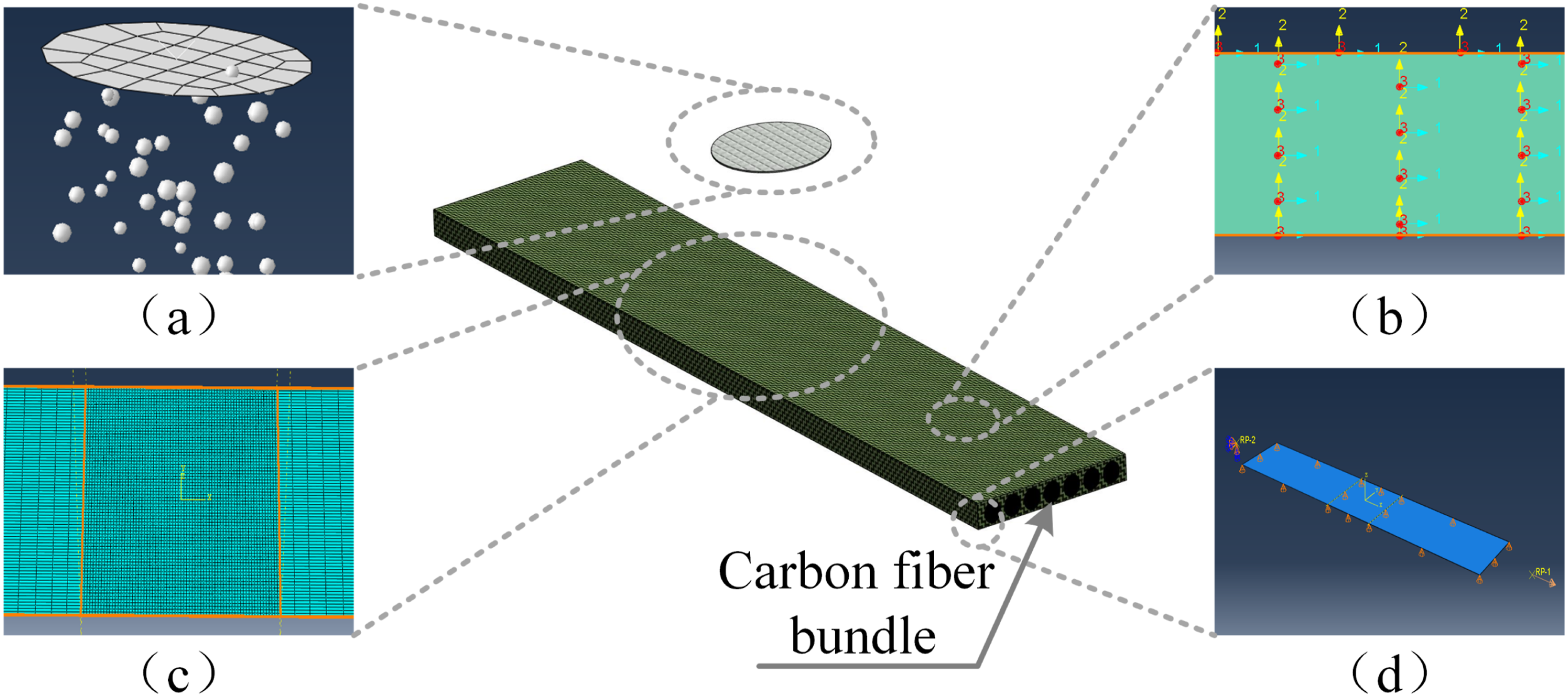
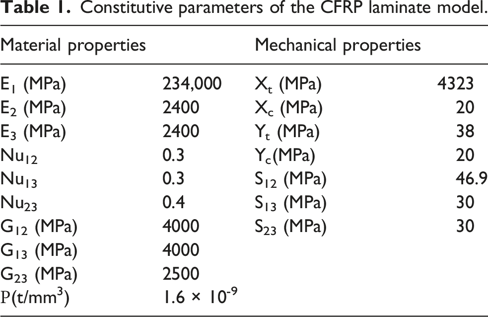
Constitutive parameters of the CFRP laminate model.
Constitutive relation of CFRP laminate
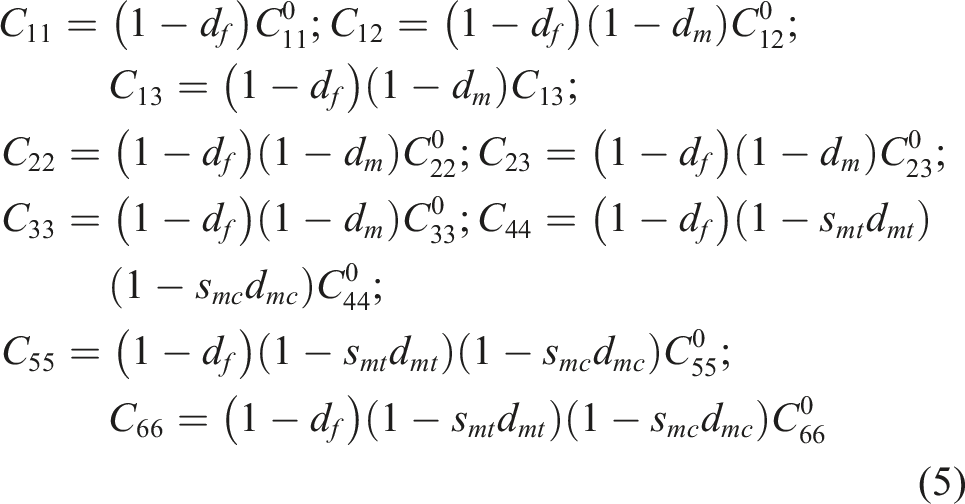
In this paper, ABAQUS software is used to simulate the residual mechanical properties of CFRP laminate subjected to wind-blown sand erosion. The 3D-Hashin criterion is adopted as the damage criterion for the composite material. The elastic constitutive equations employed29,41 are expressed as follows: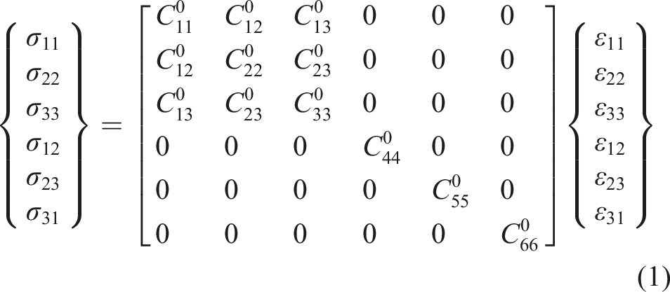
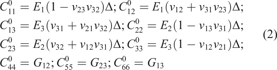

After an element undergoes damage failure, material property degradation and stiffness reduction are required. Consequently, the stiffness matrix element 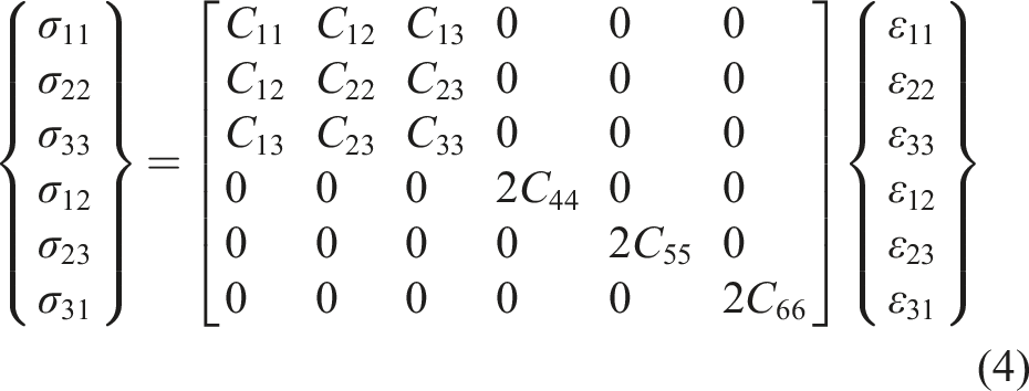


Damage initiation
To determine the onset of material damage, the 3D-Hashin damage criterion43,44 is introduced. This criterion accounts for the failure modes and the combined influence of individual stress components under interactive stress conditions. Its specific expressions are as follows:
Fiber tensile mode (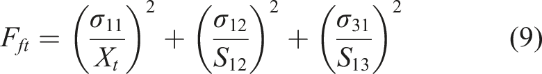
Fiber compression mode (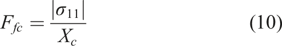
Matrix tensile mode (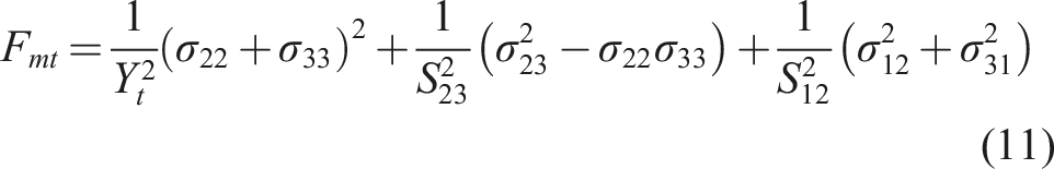
Matrix compression mode (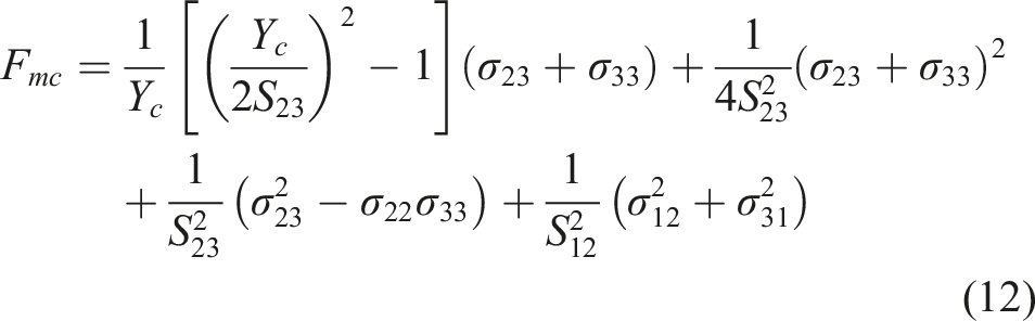
Damage evolution
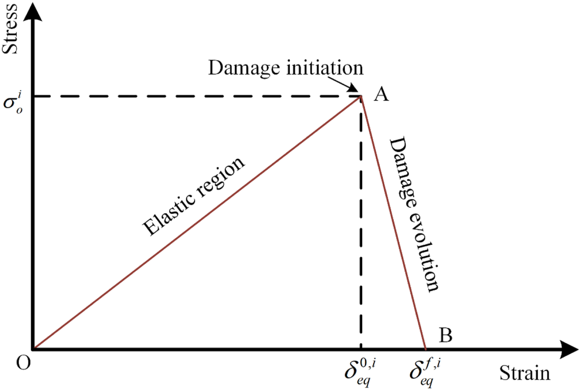
To characterize the progressive degradation of material stiffness, this paper adopts a damage evolution law based on the equivalent displacement damage coefficient.
45
In this law, the evolution of the damage variable from 0 (damage-free) to 1 (complete failure) achieves a continuous quantification of damage accumulation. By correlating damage evolution with the material fracture energy, this method ensures the validity of energy dissipation. Consequently, it effectively overcomes the mesh dependence problem in finite element simulations, rendering the computational results more objective and stable. The specific formulas are as follows: Linear stiffness degradation curve.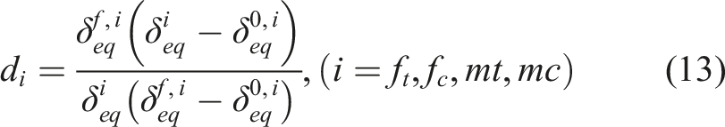
Fiber tensile mode: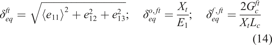
Fiber compression mode: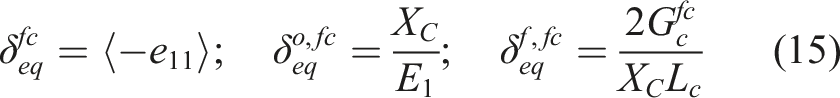
Matrix tensile mode: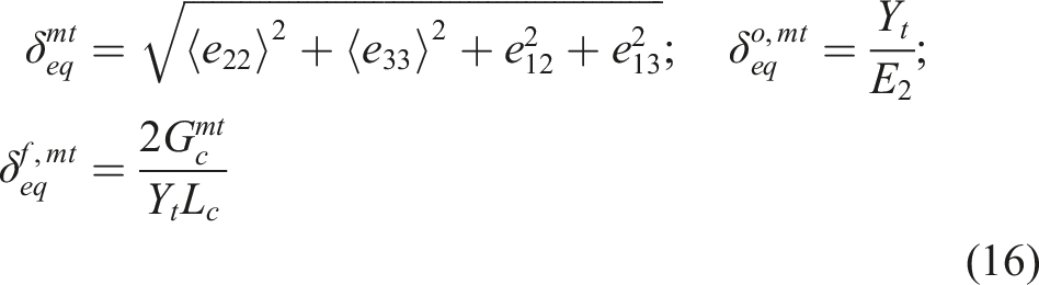
Matrix compression mode: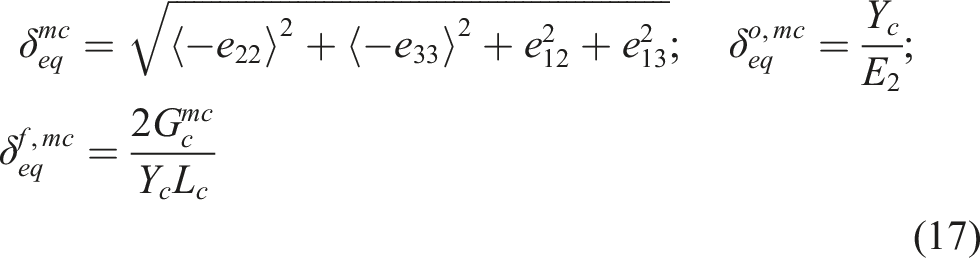
Experimental study
Specimen design
The carbon fiber fabric used in this study was supplied by a well-established Chinese manufacturer. The tensile strengths of the carbon fiber fabric and the epoxy adhesive were 4323 MPa and 38 MPa, respectively, and their elastic moduli were 234 GPa and 2.4 GPa, respectively. As shown in Figure 3, five electrical resistance strain gauges were bonded to the specimen surface to measure the strain distribution during the erosion process. To prevent premature failure at the gripping ends, end tabs were bonded to both ends of the carbon fiber fabric specimens to distribute stresses, and steel plates were used to protect against clamping-induced crushing, thereby ensuring that tensile failure occurred within the central region of the epoxy adhesive system. The designed dimensions of the test specimens were 750 mm in length and 75 mm in width. After fabrication, the specimens were cured for 12 h under standard laboratory conditions at 20°C, after which the wind-blown sand erosion tests were conducted. Macro-detail view of the specimen.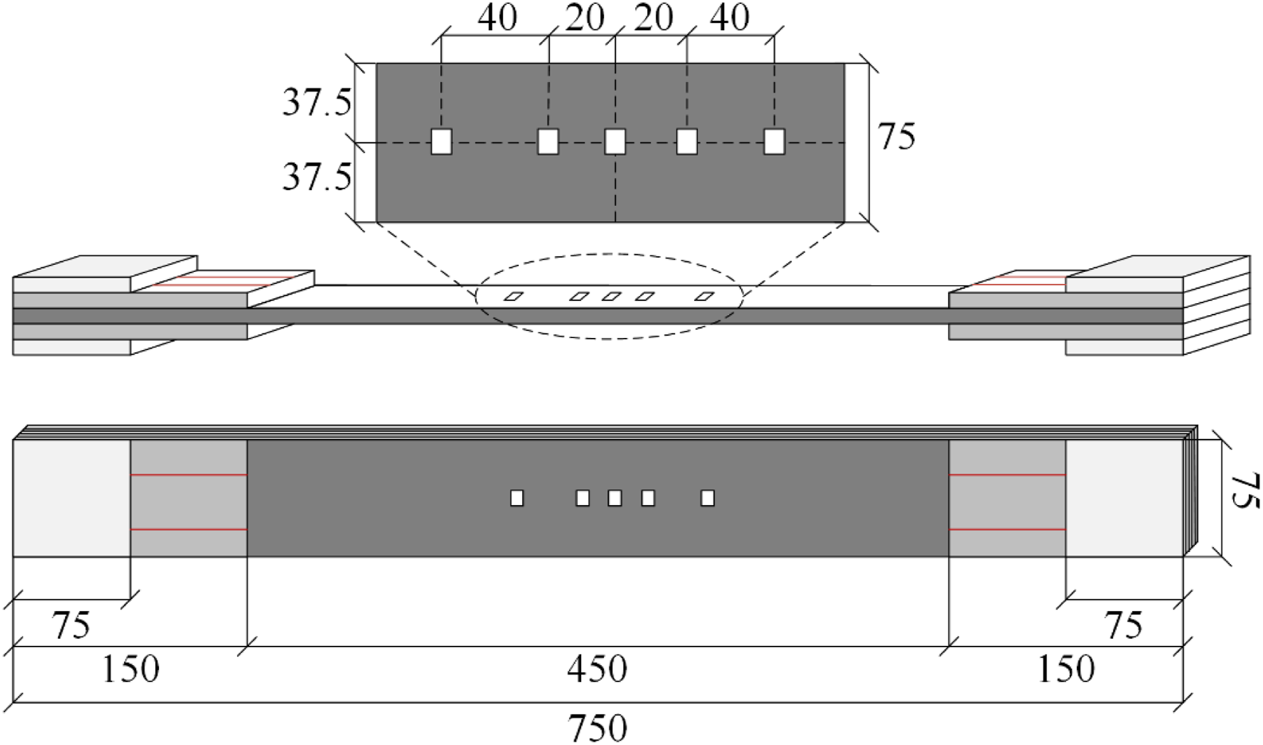
Test setup
The experiment employed the jet erosion method, which effectively simulates the characteristics of actual wind-sand environments and allows for accurate and efficient control of the erosion angle and sand flow rate, thereby facilitating the successful completion of the erosion tests. The experimental setup is illustrated in Figure 4 and consists of three parts: a high-pressure gas supply system, a sand feeding system, and an erosion chamber. Specifically, the sand feeding system was used to precisely regulate the sand delivery rate per unit time, while the erosion angle was controlled by rotating and positioning the specimen stage. Inside the erosion chamber, the nozzle diameter was set to 15 mm, and the distance from the nozzle to the specimen surface (stand-off distance) was fixed at 150 mm. Under these parameters, the diameter of the erosion-damaged area on the specimen surface closely matched the specimen width. This ensured that the central region of the specimen was subjected to uniform erosion, thereby enhancing the consistency and comparability of the experiments. Experimental system of blown-sand erosion test.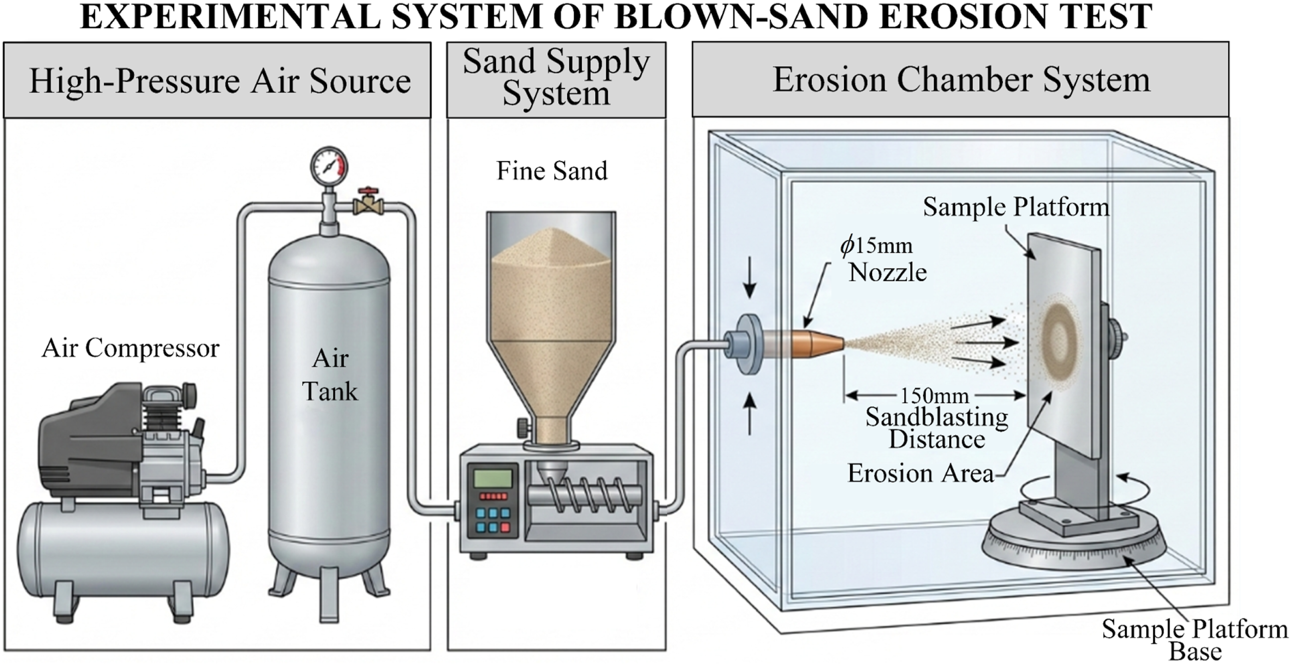
The remaining mechanical properties of the specimens subjected to wind-blown sand erosion were evaluated using an electronic universal testing machine. During the tests, the deformation of the CFRP laminate was monitored in real time by combining Digital Image Correlation (DIC) with a strain acquisition system. A high-speed camera was used to continuously capture deformation images, which were processed by the associated analysis system to generate full-field strain contours, thereby enabling precise quantification of both local and global deformation behavior of the material. The specific arrangement of the experimental setup is shown in Figure 5. Setup of residual mechanical properties test.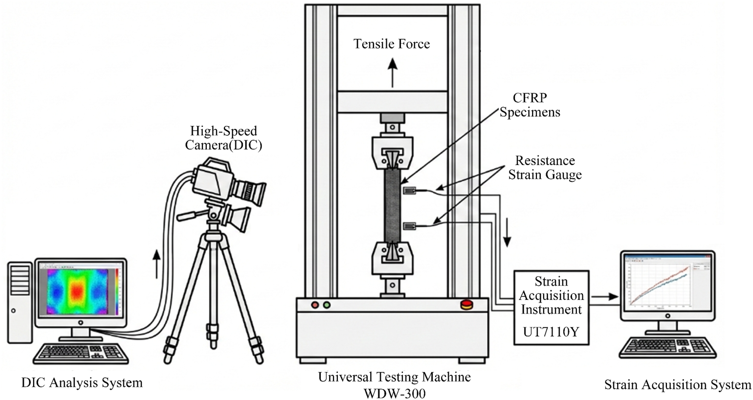
Experimental results of wind-blown sand erosion on CFRP laminate
Mechanical properties of CFRP laminate after wind-blown sand erosion
Test conditions.
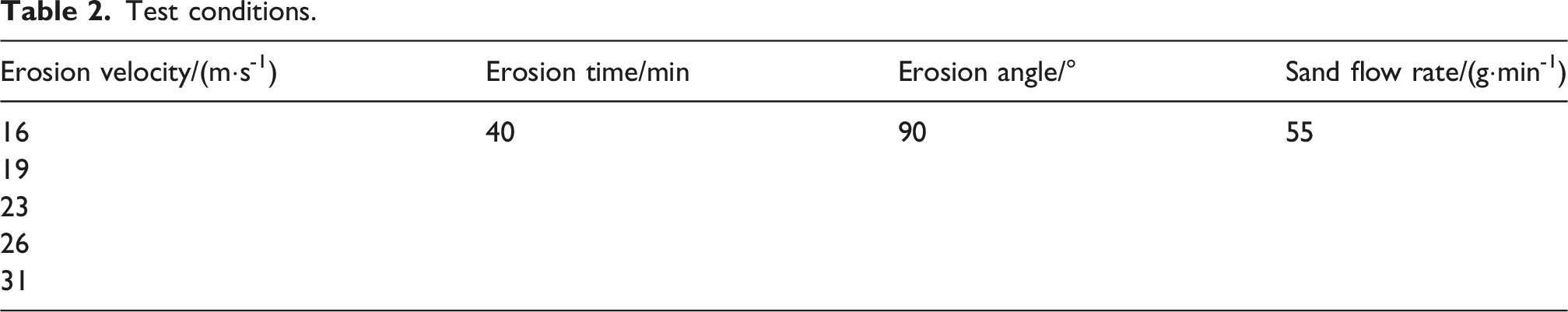
Figure 6 illustrates the evolutionary patterns of the tensile strength and elastic modulus of CFRP laminate following wind-blown sand erosion. It is evident that wind-blown sand erosion significantly weakens the tensile properties of the material. At an erosion angle of 90°, the tensile strength of the CFRP laminate exhibited a clear downward trend with increasing erosion velocity; the maximum strength loss occurred at 31 m/s, with a reduction of approximately 23.16%. Meanwhile, while the elastic modulus fluctuated slightly with increasing velocity, it remained generally stable overall. Notably, the most significant decrease in elastic modulus was observed at 26 m/s, with a reduction of 7.2%. As an intrinsic property, the elastic modulus is primarily determined by the material’s composition and internal structure. Although wind-blown sand erosion, as a surface physical damage process, may induce surface fiber breakage or resin spalling in the CFRP laminate, it does not significantly alter the overall internal structure of the material. Consequently, within the range of erosion parameters examined in this study, the elastic modulus of the CFRP laminate showed no drastic changes, demonstrating excellent stability. In summary, wind-blown sand erosion has a minor impact on the elastic modulus of CFRP laminate, but it significantly degrades their tensile strength. Mechanical properties of CFRP laminate after wind-blown sand erosion.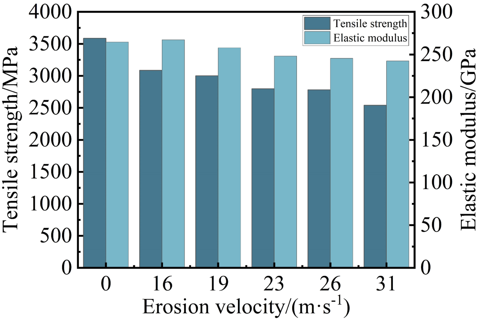
Damage morphology of CFRP laminate after wind-blown sand erosion
As shown in Figure 7, significant damage occurred on the surface of the CFRP laminate after wind-blown sand erosion. At an erosion velocity of 16 m/s, slight damage was visible on the specimen surface, accompanied by localized slight fragmentation of the epoxy resin matrix. As the erosion velocity increased to 19 m/s and 23 m/s, the degree of surface damage intensified significantly, and spalling of the surface resin matrix occurred. When the velocity further increased to 26 m/s, the spalling of the resin matrix aggravated, internal fibers became exposed, and partial fiber bundles fractured. At an erosion velocity of 31 m/s, the surface damage was the most severe, characterized by large-scale spalling of the resin matrix and extensive exposure of internal fibers, which exhibited obvious fracture and damage under the continuous impact of wind-blown sand particles. Damage morphology of CFRP laminate after wind-blown sand erosion: (a) 16 m/s; (b) 19 m/s; (c) 23 m/s; (d) 23 m/s; (e) 31 m/s.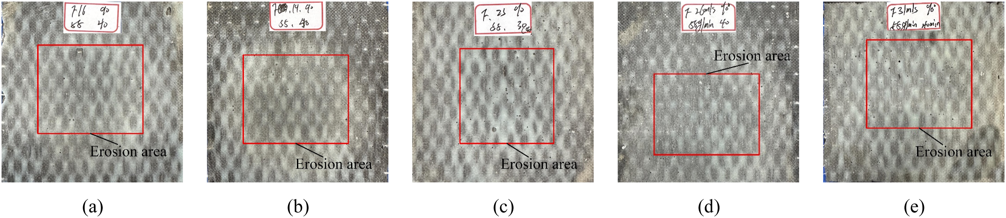
Damage mechanism of CFRP laminate under wind-blown sand erosion
The damage to CFRP fabrics caused by wind-blown sand erosion is a continuous process evolving from the accumulation of microscopic defects to the deterioration of macroscopic properties. As shown in Figure 8, this process is primarily driven by the kinetic energy carried by impacting sand particles, which is predominantly converted into localized compressive stress at the impact points. Specifically, high-speed sand particles striking the surface of the CFRP fabric initially induce elastoplastic deformation and denudation of the epoxy resin matrix. As erosion progresses, the surface layer of the matrix gradually wears away, thereby exposing the internal fibers. These exposed fibers are then subjected to direct impact, leading to fracture or fragmentation under erosive action. Ultimately, these microscopic structural damages directly cause macroscopic performance degradation: the decrease in tensile strength primarily stems from fiber fracture, while the reduction in stiffness is attributed to the combined effects of interfacial failure and microcracking. Consequently, the damage of CFRP fabrics by wind-blown sand erosion is essentially a progressive physical destruction process that is driven by kinetic energy, proceeds from the surface to the interior, and extends from the interface to the whole structure. Damage mechanism of CFRP laminate under wind-blown sand erosion.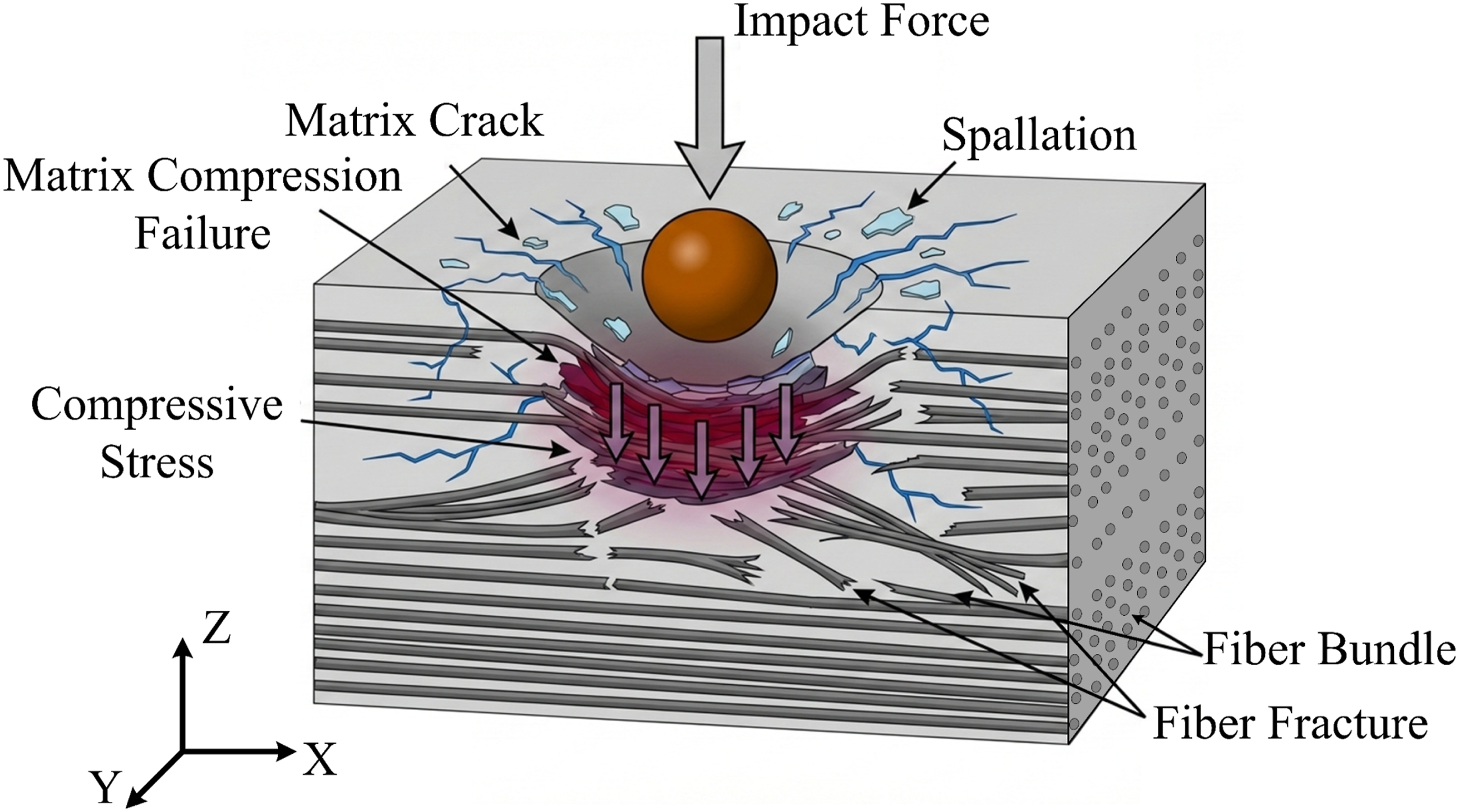
Model validation
Single element verification
The specimen parameters obtained through experiments are used to construct the finite element model to perform numerical prediction and simulation analysis of the experimental process. This model couples the material property parameters via a VUMAT user material subroutine written in Fortran, thereby achieving a more accurate simulation of the tensile mechanical behavior after erosion. The stress update algorithm and the specific calculation flow within the VUMAT subroutine are illustrated in Figure 9. In this study, a dynamic explicit algorithm is employed. Compared to static algorithms, the dynamic explicit algorithm offers higher computational accuracy when dealing with large deformation nonlinear problems and demonstrates significant advantages in the efficient solution of impact-type simulations. Flowchart of VUMAT workflow.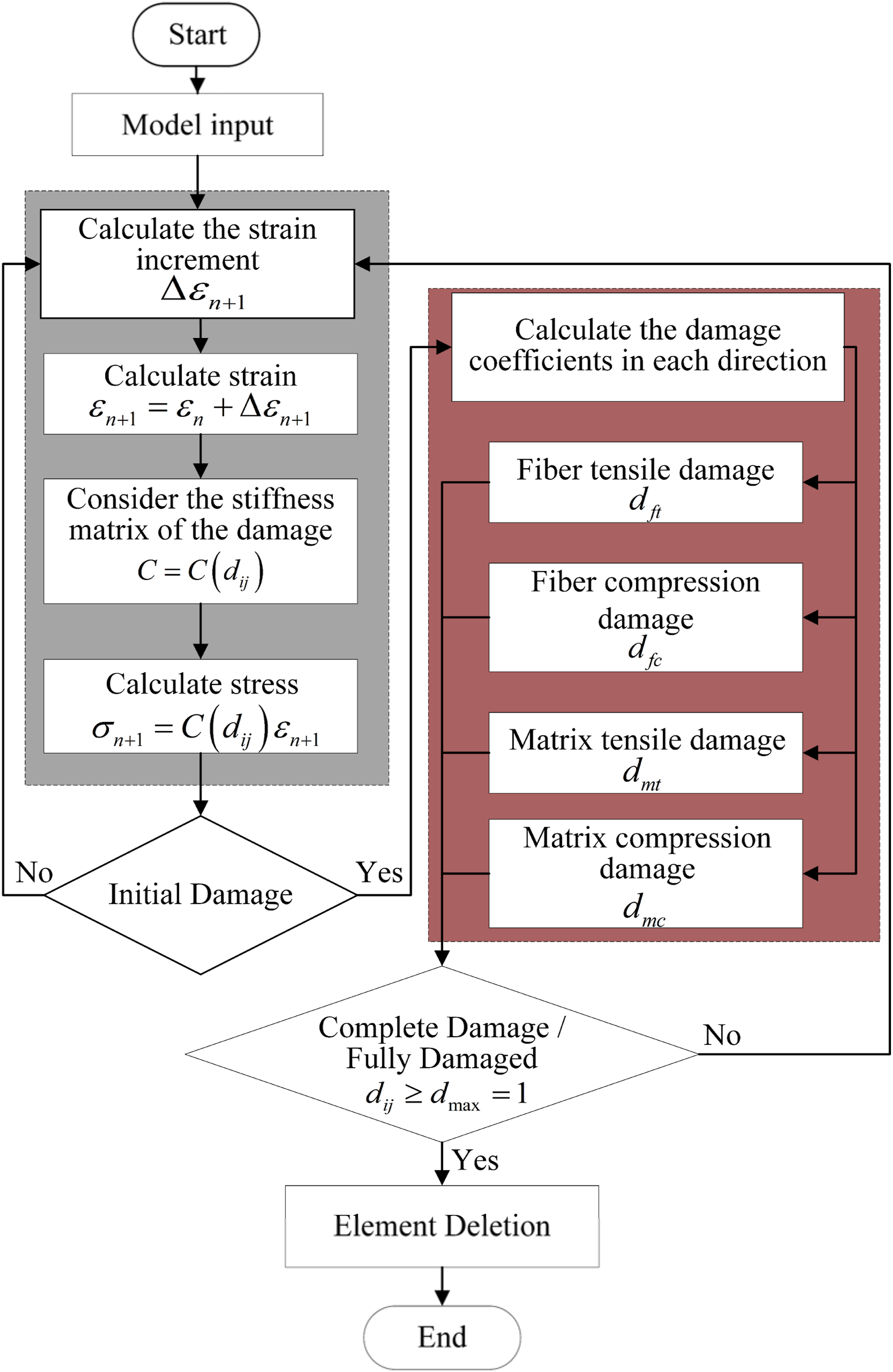
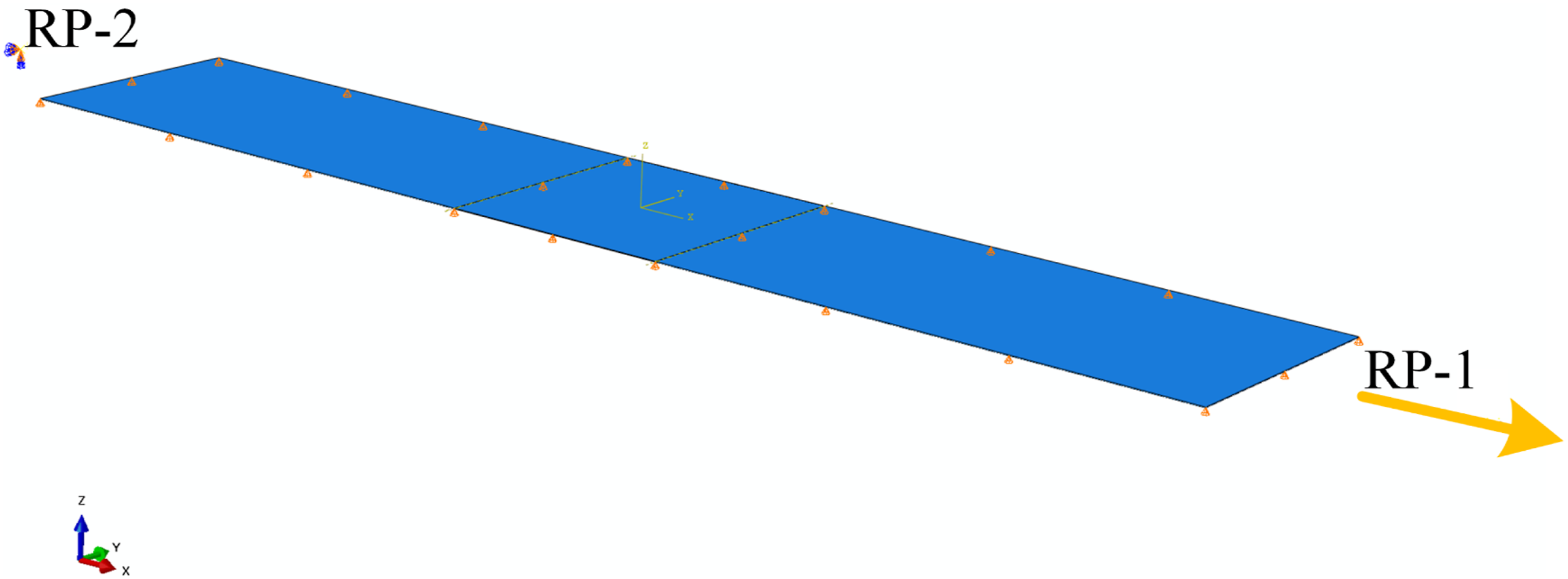
To verify the accuracy of the written VUMAT subroutine, and considering that the actual thickness of the CFRP laminate is relatively thin (0.167 mm), it was found during the simulation process that if a single mesh (element) were used for verification, the elements in the thickness direction would be prone to severe distortion. Therefore, this study employs a coarse mesh model of the overall structure for verification, rather than targeting a single mesh element. In the result analysis phase, one of the typical element meshes is selected for comparative verification. To validate the accuracy of the model, a uniaxial tensile simulation along the fiber direction was conducted, and the model was assigned the actual material parameters of the CFRP laminate. Correspondingly, a 3D solid element model was established with clearly defined material orientations, as shown in Figure 10, and the analysis steps, and boundary conditions were set as shown in Figure 11. Material orientation. Boundary conditions.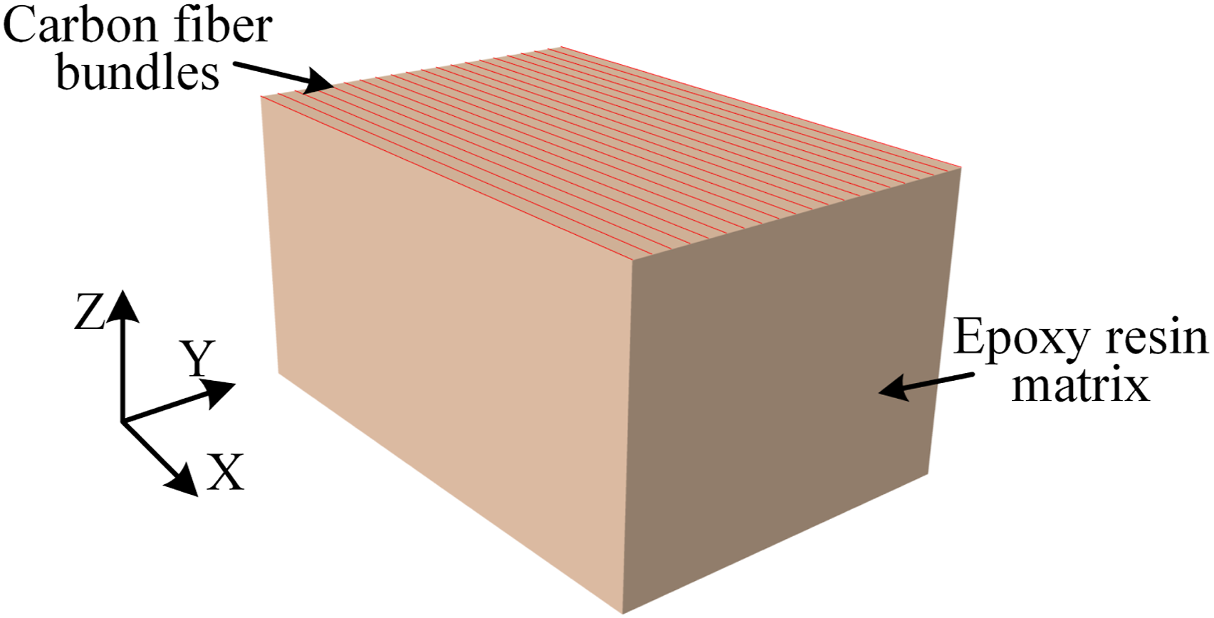
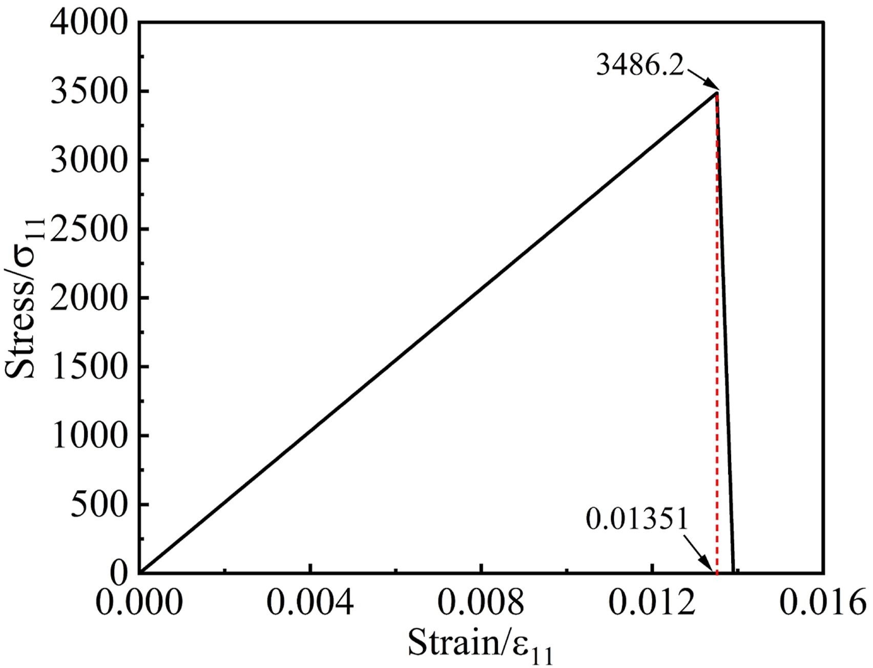
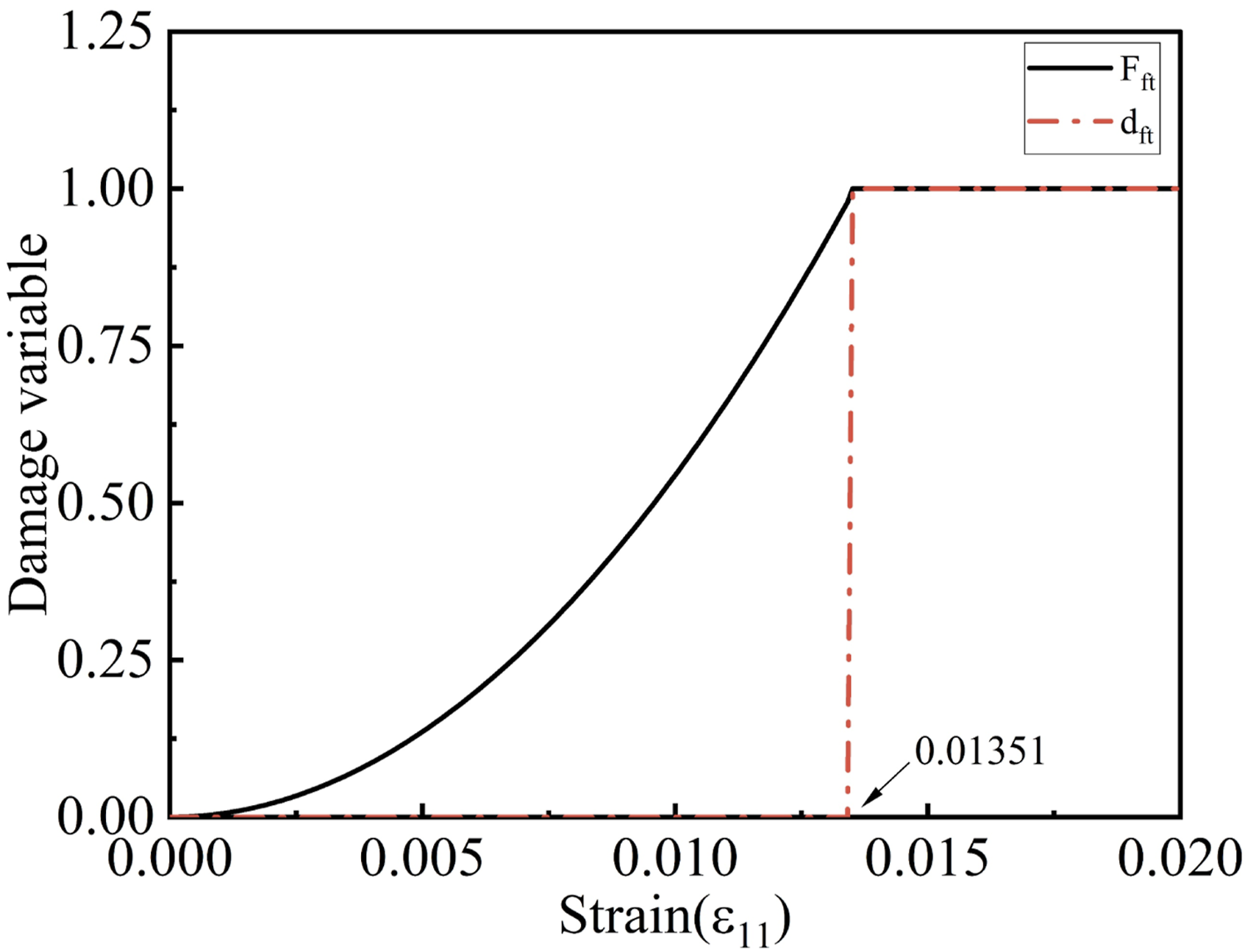
A comparison between the simulation results of the material’s mechanical properties and the experimental data is presented in Figure 12. The bar chart indicates that the simulated tensile strength and elastic modulus agree well with the experimental values, with relative errors of 2.7% for tensile strength and 3.8% for elastic modulus. Figure 13 shows the stress-strain response curve obtained from the simulation. At a strain of 0.01,351, the simulated ultimate stress is 3486.2 MPa, which is close to the experimentally measured ultimate stress of 3586.5 MPa, further confirming the reliability of the established model. Figure 14 illustrates the variations in the fiber initial damage coefficient Comparison of the experimental results with the simulation results. Stress-strain response curve. Damage variable - strain response curve.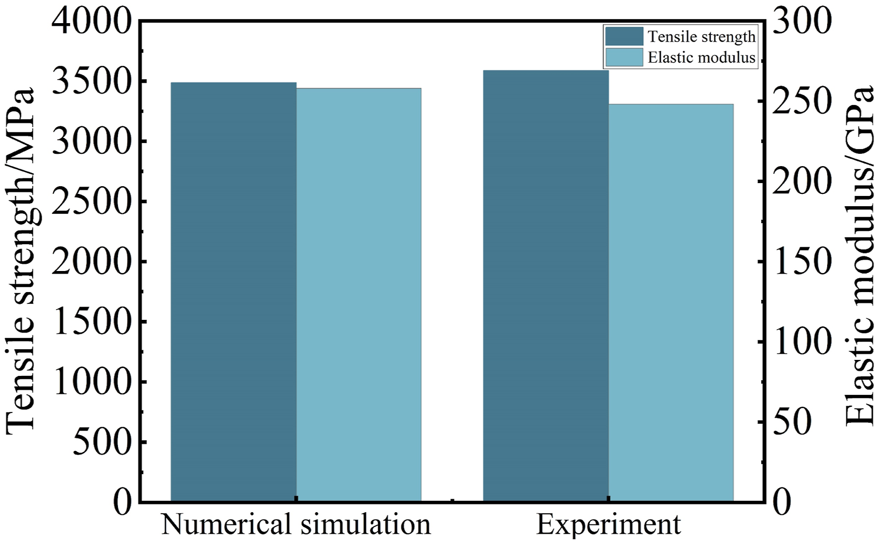
Mesh sensitivity analysis
To ensure the reliability and accuracy of numerical simulation results, it is crucial to reduce the mesh dependency of the model and guarantee its convergence. This study evaluates the convergence behavior of the model through a mesh sensitivity analysis, specifically by employing a method of gradually reducing the mesh size. In the CFRP laminate model, reference planes are used for partitioning, and mesh refinement is applied to the erosion zone. Four sets of mesh sizes (5 mm, 3 mm, 1 mm, and 0.5 mm) were defined for the sensitivity analysis of this region. As shown in Figure 15, the axial tensile simulation results indicate that the load-displacement curves for different mesh sizes overlap significantly before reaching the peak load, suggesting that the response in this stage is essentially independent of the mesh; however, the post-peak stage exhibits slight mesh dependency. Considering computational efficiency and convergence stability comprehensively, the model demonstrates good convergence and stable results with a 1 mm mesh size. Consequently, the mesh size for the erosion zone is determined to be 1 mm. To balance computational costs, the non-erosion region utilizes a bias-based gradient mesh where the element size gradually increases from 1 mm to 15 mm. This mesh strategy significantly improves computational efficiency while ensuring computational accuracy and convergence. Load-displacement responses of elements of different sizes under tensile simulation.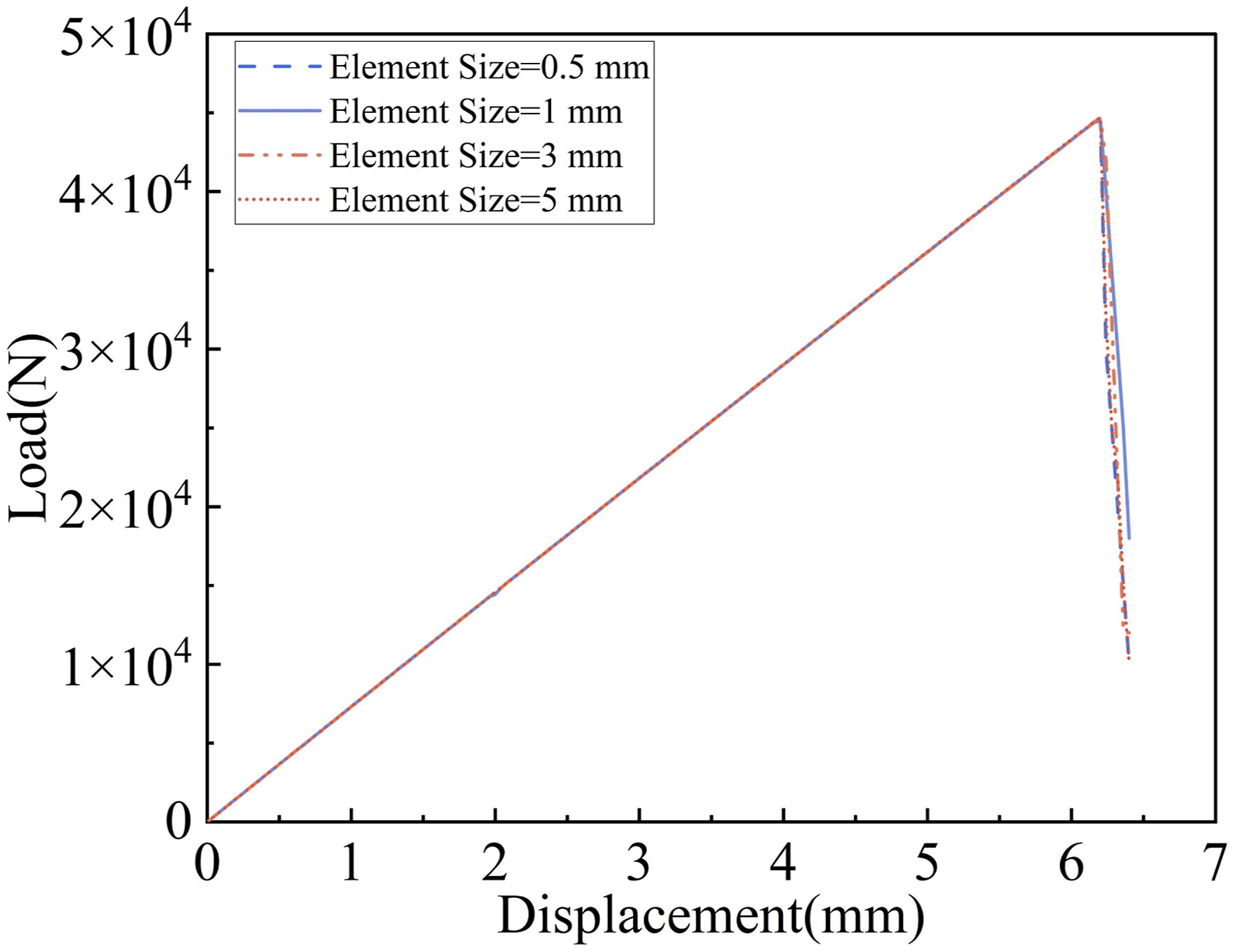
Comparison of mechanical properties after erosion
In this section, the mechanical property degradation of the CFRP laminate model under discrete particle erosion was numerically simulated and compared with experimental results, as shown in Figure 16. As shown in Figure 16(a), with the continuous increase of particle impact velocity, the simulated tensile strength of the CFRP laminate gradually decreases. This degradation trend is consistent with the law observed in the experiments where strength declines with rising velocity. The error range between the simulated and experimental values under various velocity conditions is between 1.37% and 4.18%, indicating that the model possesses high prediction accuracy. Figure 16(b) illustrates the comparison between the simulated and experimental values of the elastic modulus of the CFRP laminate after erosion. The simulation results indicate that the elastic modulus does not change significantly with the increase of erosion velocity, which is basically consistent with the experimental conclusions. Meanwhile, the simulated values are close to the experimental ones, with an error range of 3.56%–6.48%. It is worth noting that, as seen from the bar chart, the experimental values exhibit a slight decrease at 23 m/s, 26 m/s, and 31 m/s, whereas the simulated values remain stable. This discrepancy may stem from the relatively ideal simulation environment, whereas in actual experiments, factors such as fiber dispersion and manufacturing errors can induce slight fluctuations in material properties, thereby resulting in a slight reduction in the experimental values of the elastic modulus. Mechanical properties of CFRP laminate after wind-blown sand erosion: (a) Tensile strength; (b) Elastic modulus.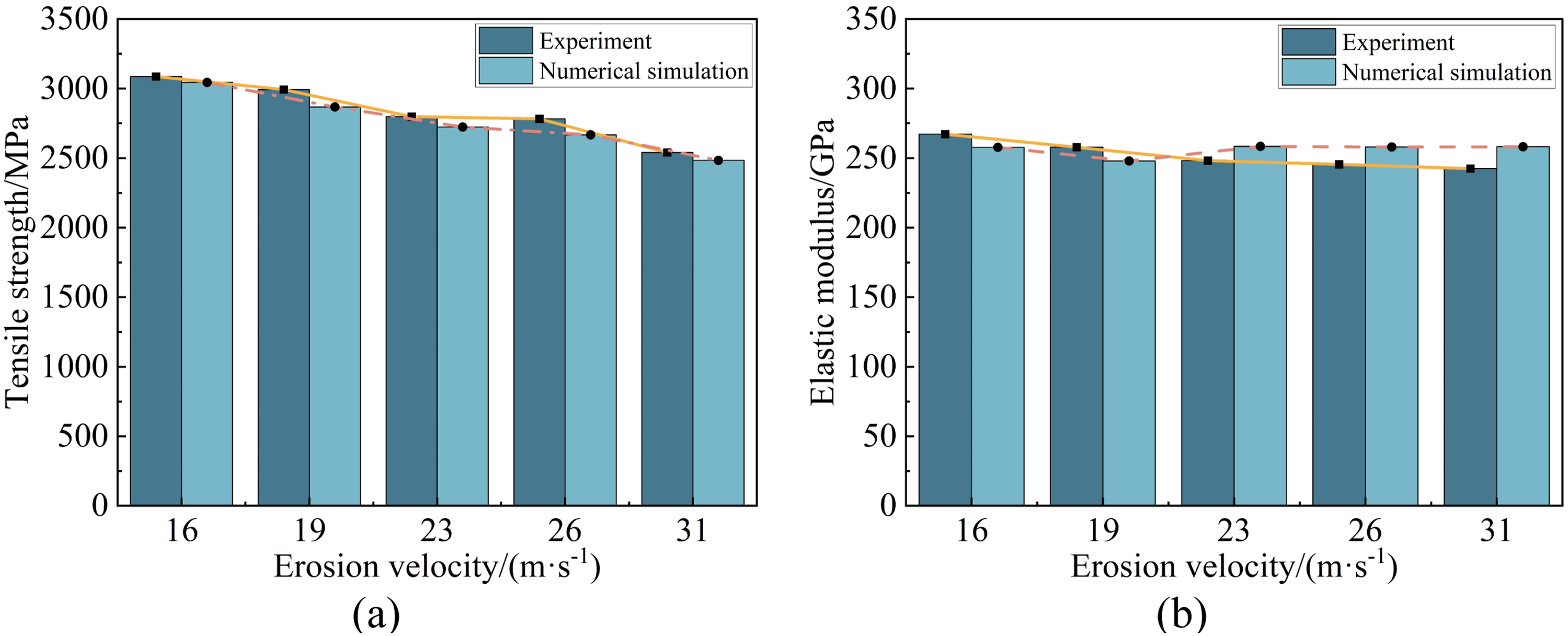
In summary, the simulation results of the model agree well with the experimental results, and the errors fall within an acceptable range for engineering applications. Therefore, the model can be used for further analysis and prediction of the mechanical properties of CFRP laminate under Wind-Blown Sand Erosion conditions.
Damage morphology after particle impact
Under particle erosion at different initial velocities (16 m/s, 19 m/s, 23 m/s, 26 m/s, and 31 m/s), the surfaces of CFRP laminate specimens exhibited varying degrees of damage morphologies. Similarly, in numerical simulation, the material surface is primarily subjected to compressive stress from the particles upon impact, a stress shared by both the fiber bundles and the matrix. Therefore, this study adopts the fiber compression initial damage coefficient (
At the relatively low impact velocity of 16 m/s, the kinetic energy of the particles is relatively low, yet the initial damage coefficients Erosion damage diagram of 16 m/s.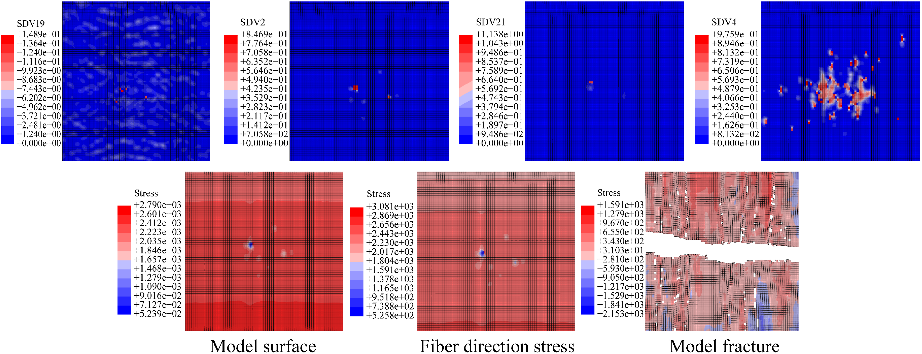
When the initial particle velocity is increased to 19 m/s and 23 m/s, the damage behavior of the model undergoes significant changes. As shown in Figures 18 and 19, the contours of SDV19 and SDV21 indicate a marked increase in the number of elements whose damage coefficients have reached the threshold compared to the 16 m/s case. Meanwhile, the number of elements undergoing strength degradation in the damage evolution coefficient contours (SDV2 and SDV4) also rises significantly. Distinct holes can be observed on the model surface, indicating that some elements have reached their ultimate strength and have been deleted. It is worth noting that although elements approaching 1.0 are observed in the SDV2 and SDV4 contours, values equal to or greater than 1.0 are not visible. This is because once the damage evolution coefficient reaches 1.0, the corresponding element is immediately deleted and therefore no longer appears in the contours. The stress contour in the fiber direction further reveals a significant increase in dark blue spots, reflecting that internal damage within the impacted elements has caused them to lose their tensile load-bearing capacity. Furthermore, the appearance of dark red spots in the figures indicates the occurrence of local stress concentration due to element deletion. As the external loading continues, these stress concentration zones will undergo fracture first, ultimately triggering the failure of the overall material. Erosion damage diagram of 19 m/s. Erosion damage diagram of 23 m/s.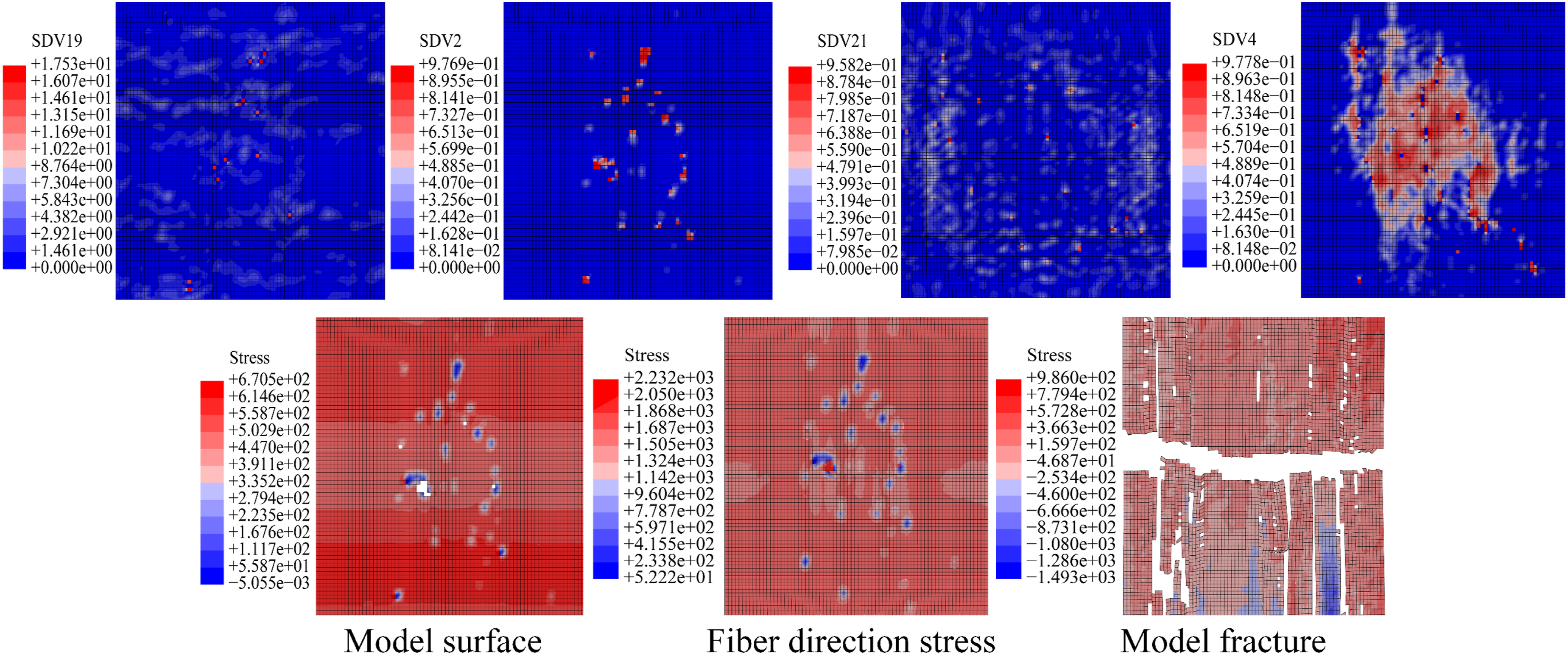
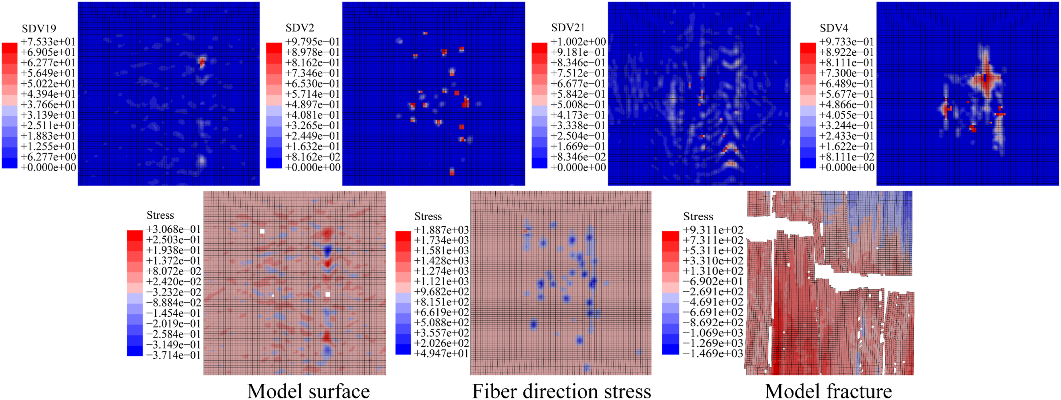
Figure 20 illustrates a significant increase in element deletion on the specimen surface when the erosion velocity is raised to 26 m/s. The damage coefficient contour SDV19 reveals that the damage coefficients of a large number of elements have exceeded 1.0, indicating significant damage to the fibers under impact loading. Meanwhile, the SDV21 contour reflects that the matrix damage areas are relatively concentrated; however, no elements with values greater than or equal to 1 appear in this contour. Combined with the SDV4 damage evolution coefficient contour, it can be inferred that elements in SDV21 that originally exceeded 1.0 have been deleted due to reaching the ultimate strength, and thus are no longer displayed in the SDV21 contour. Observing the damaged surface of the model, it is evident that the number of deleted elements has increased significantly. The overall proliferation of blue elements, which represent the loss of load-bearing capacity, indicates that the material damage has become severe, ultimately leading to a decrease in the ultimate strength of the overall model. Erosion damage diagram of 26 m/s.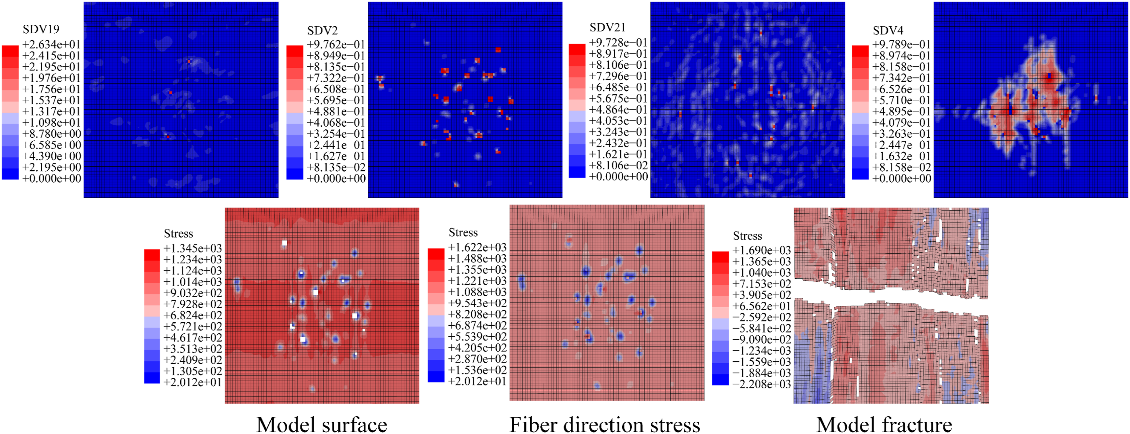
As shown in Figure 21, when the velocity is further increased to 31 m/s, the number of deleted elements on the specimen surface rises sharply. The damage coefficient contour SDV19 indicates significant fiber damage, while the SDV21 contour shows that the matrix damage coefficients generally exceed 1.0, with more concentrated damage zones. The corresponding damage evolution coefficient contours (SDV4) also exhibit a dense distribution of high-value elements, reflecting a highly concentrated spatial pattern of damage evolution. Multiple large-area holes are visible in the model surface morphology contour, indicating widespread generation of failed elements, and impact damage has extended significantly from the surface into the interior. At this stage, the CFRP laminate model is in a severely damaged state, with markedly degraded macroscopic mechanical properties. This simulated morphology is consistent with the severe damage characteristics of the material observed in high-speed Wind-Blown Sand Erosion experiments. Erosion damage diagram of 31 m/s.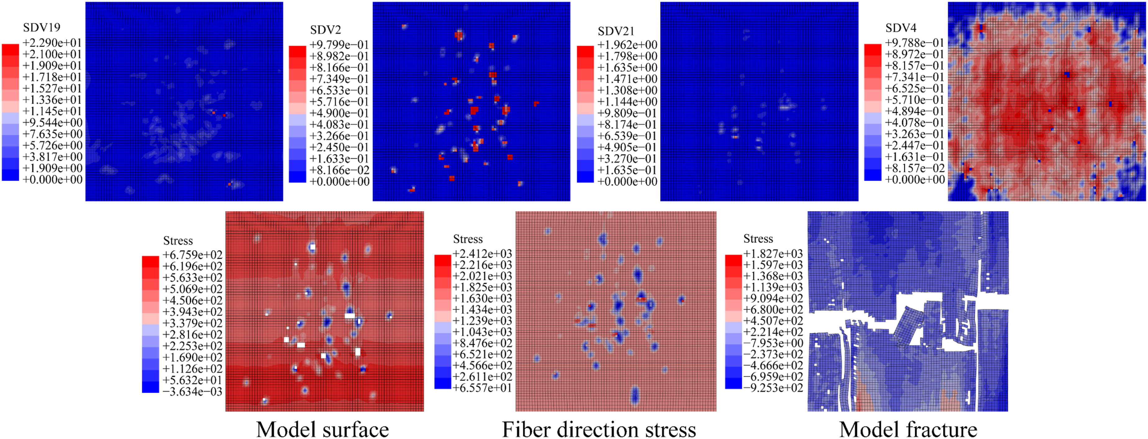
Prediction of mechanical properties
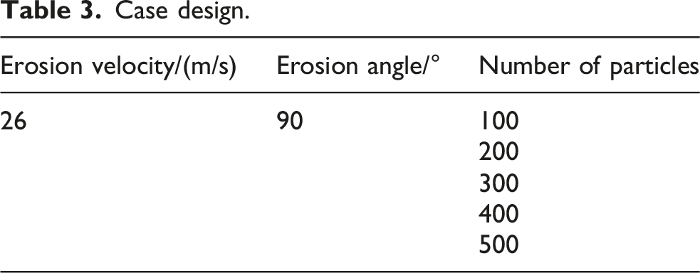
Case design
Case design.
Mechanical properties of CFRP laminate model post-erosion
Figure 22 illustrates the evolution of the mechanical properties of CFRP laminate under erosion conditions with different numbers of particles, as predicted by the ABAQUS model. It can be observed that when the number of particles is 100, 200, and 300, the predicted tensile strength of the CFRP laminate model does not exhibit a significant decrease. This may be attributed to the relatively small number of particles; the cumulative energy upon impact on the CFRP laminate model is low and insufficient to cause significant damage to the surface elements, thus the overall mechanical properties remain relatively stable. As the number of particles increases to 400, the tensile strength of the CFRP laminate exhibits a significant decline, decreasing by approximately 16.71% compared to the 300-particle case. At this stage, the total energy exerted by particle impact on the CFRP laminate model is substantial, causing noticeable damage to the material. When the number of particles further increases to 500, the tensile strength continues to decrease, dropping by approximately 29.26% relative to the 300-particle case. The aforementioned results indicate that as the number of particles increases, the damage sustained by the CFRP laminate model intensifies. Consequently, the number of elements deleted due to reaching the ultimate strength increases correspondingly, leading to a distinct deterioration trend in the tensile strength. Mechanical properties of CFRP laminate model after erosion with different numbers of particles.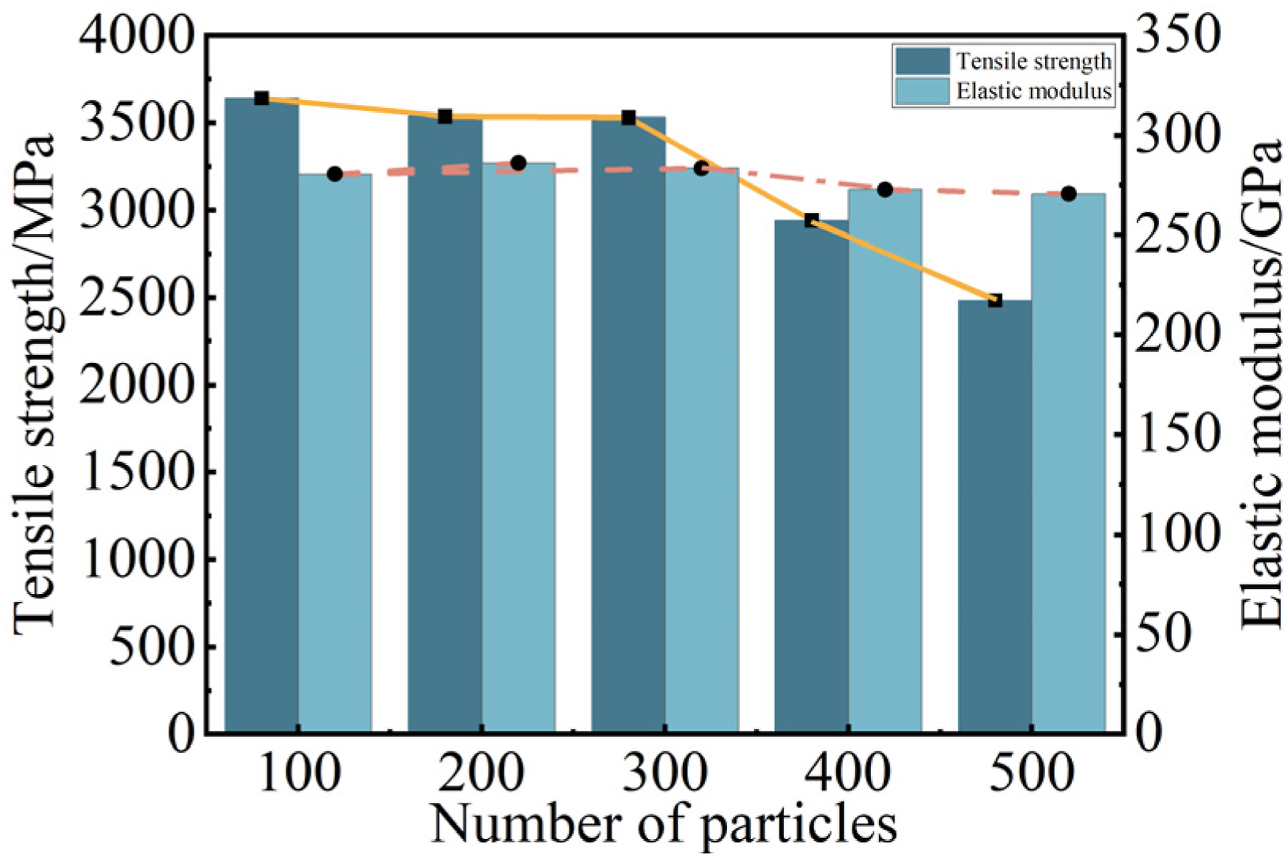
It is worth noting that the elastic modulus of the CFRP laminate model does not exhibit significant fluctuations under any of the particle number cases, remaining relatively stable throughout. This indicates that, although particle erosion in the predictive model leads to a decrease in macroscopic strength, it does not alter the fundamental elastic properties of the material.
Damage morphology of CFRP laminate model post-erosion
The erosion damage morphology on the surface of the CFRP laminate model under different numbers of particles is shown in the figure. From the damage morphology images in Figure 23(a)–(c), it can be seen that at an initial velocity of 26 m/s and with particle numbers of 100, 200, and 300, no obvious damage appears on the surface of the CFRP laminate model. The dark blue spots in the damage contour indicate that the elements at these locations have met the damage initiation criterion; microcracks may have initiated or softening may have occurred internally, but since they have not yet reached the ultimate strength, these elements are retained and can continue to bear tensile stress. As the number of particles increases to 400, voids begin to appear on the model surface, as shown in Figure 23(d). This is because the increased particle number leads to a rise in cumulative impact energy; some surface elements reach their strength limit with a damage evolution coefficient greater than or equal to 1.0, and are therefore deleted. These deleted elements no longer participate in load carrying, resulting in a decrease in the ultimate tensile strength of the model. When the number of particles further increases to 500, a large number of dense voids appear on the surface of the CFRP laminate model. The increase in particle number significantly aggravates material damage; more surface elements are deleted due to reaching the failure condition, thereby severely weakening the overall tensile strength of the model. Surface damage morphology of CFRP laminate model after erosion with different numbers of particles: (a) 100 particles; (b) 200 particles; (c) 300 particles; (d) 400 particles; (e) 500 particles.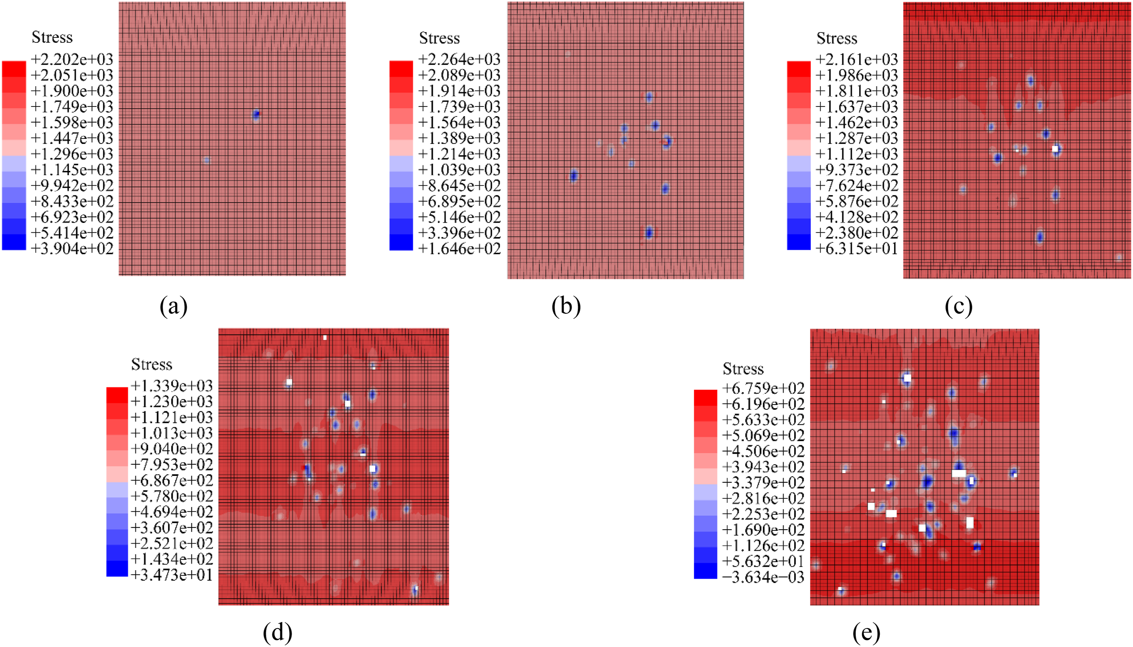
Analysis of prediction accuracy
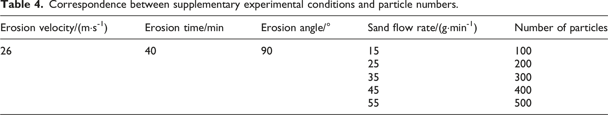
Correspondence between supplementary experimental conditions and particle numbers.
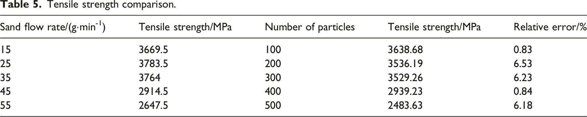
Tensile strength comparison.
Elastic modulus comparison.
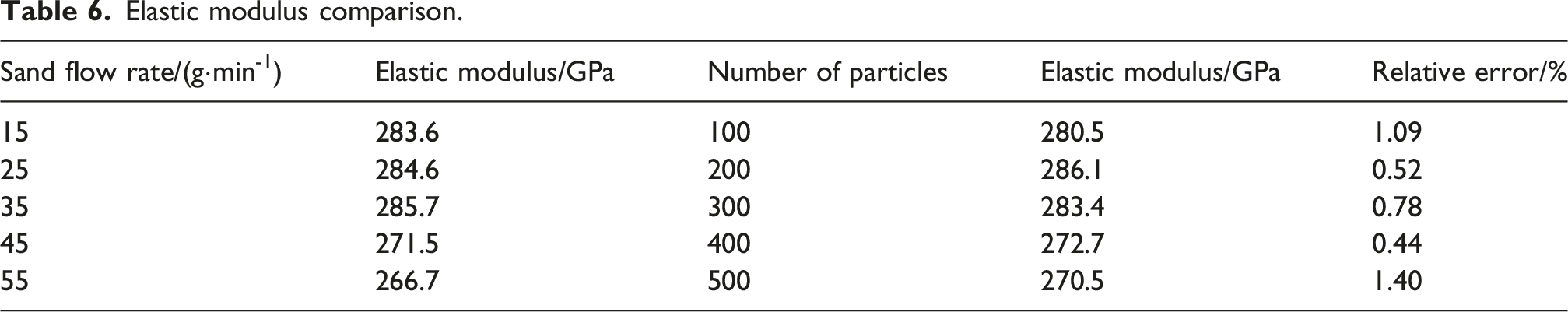
Figure 24 illustrates the evolution of the surface morphology of CFRP laminate after wind-blown sand erosion at different sand flow rates. At lower sand flow rates (15, 25, and 35 g/min), no significant macroscopic damage was observed on the material surface, with only slight spalling of the epoxy resin matrix (Figure 24(a)–(c)). When the sand flow rate increased to 45 g/min, the degree of damage significantly intensified, characterized by large-area spalling of the resin matrix, fiber exposure, and extensive fracture (Figure 24(d)). Upon further increasing the sand flow rate to 55 g/min, distinct erosion pits formed on the surface, and the damage further propagated (Figure 24(e)). The damage modes observed in the aforementioned experiments are highly consistent with the model predictions shown in Figure 11, both demonstrating a progressive damage process ranging from surface resin abrasion to fiber fracture and finally to macroscopic pitting. In summary, the erosion model established in this study exhibits high prediction accuracy and can reliably simulate the degradation of mechanical properties and the damage evolution process of CFRP laminate under real wind-sand environments, thereby providing an analytical basis for the durability assessment of CFRR structures in such conditions. Wind-blown sand erosion damage morphology of CFRP laminate under different sand flow rates: (a) 15 g/min; (b) 25 g/min; (c) 35 g/min; (d)45 g/min; (e) 55 g/min.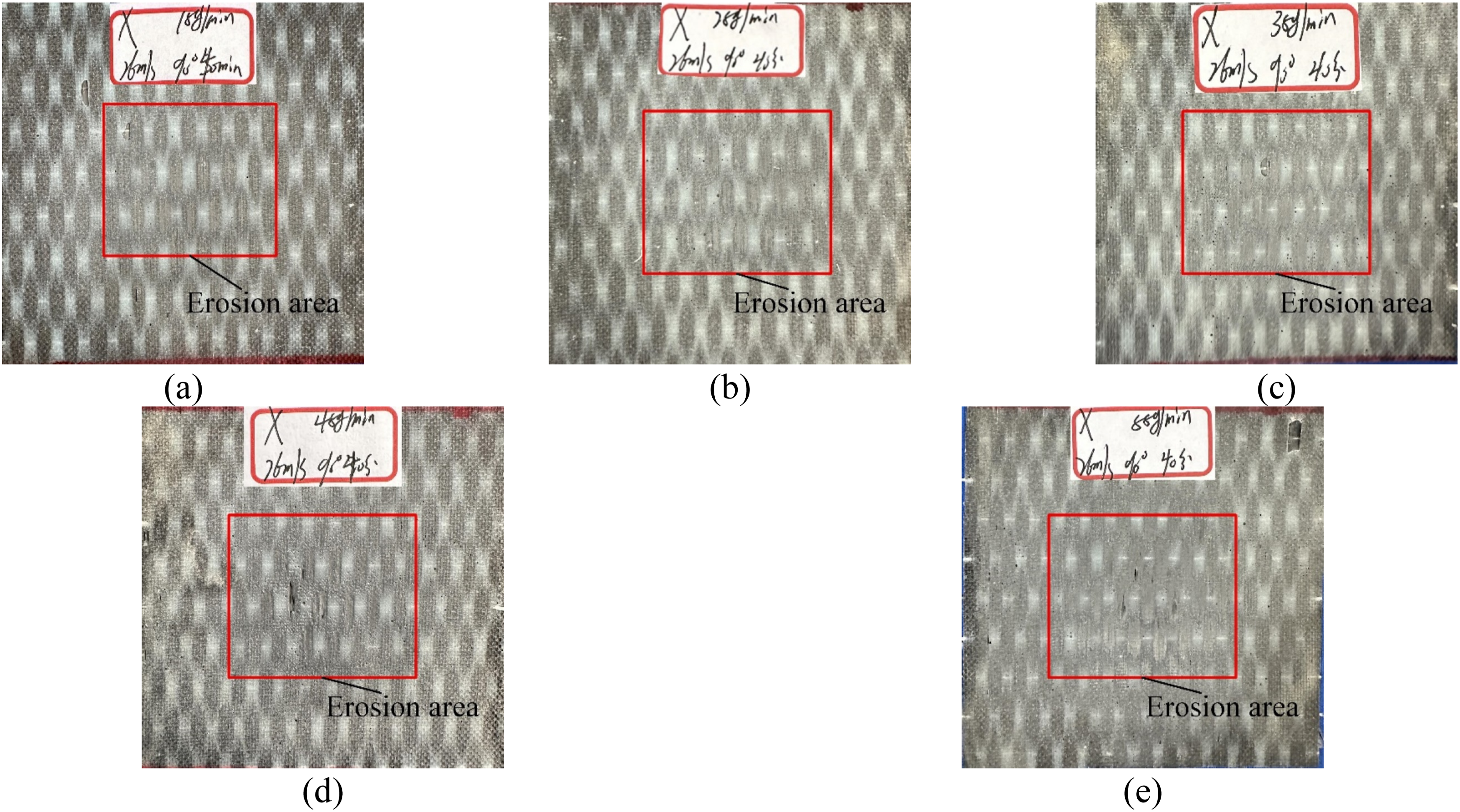
It should be objectively noted that, constrained by the ultra-thin thickness of the CFRP laminate (0.167 mm) and the size effect induced by mesh discretization in the numerical model, the comparison of damage morphology in this study primarily focuses on the qualitative agreement of evolutionary patterns and trends, rather than directly extracting damage area or depth for quantitative measurement. However, the high consistency of the macroscopic tensile strength degradation data (with an error of less than 5%) indirectly corroborates the reliability of the model in assessing the extent of damage evolution from a mechanical response perspective. This provides robust support for the qualitative morphological comparison, thereby validating the accuracy of the proposed model based on damage morphological features.
Conclusion
In this study, the erosion process of CFRP laminate by wind-sand particles was simulated using ABAQUS software, where the dynamic erosion of particles was achieved via a built-in particle generator. A VUMAT subroutine was developed based on the 3D Hashin failure criterion to characterize the material’s damage initiation, evolution, and stiffness degradation behavior during the erosion process. The subroutine was validated at the element scale, and a mesh sensitivity analysis was performed on the computational model. On this basis, the evolution of damage morphology of CFRP laminate under different erosion velocities was systematically analyzed, and the simulation results were verified by comparison with experimentally measured variations in mechanical properties. Finally, the model was utilized to predict the mechanical property degradation and damage morphology characteristics of CFRP laminate under different sand flow rates. The conclusions are drawn as follows: (1) In the wind-sand erosion tests, the tensile strength of the CFRP laminate exhibited a significant downward trend with increasing erosion velocity. At an erosion velocity of 31 m/s, the tensile strength experienced its maximum reduction of approximately 23.16%. However, the increased erosion velocity had no noticeable impact on the elastic modulus of the CFRP laminate. The pronounced degradation in tensile strength is attributed to the fracture failure of locally load-bearing fibers driven by the kinetic energy of the sand particles. In contrast, the stability of the elastic modulus is primarily due to the fact that wind-sand erosion is essentially a surface physical damage mechanism; it mainly induces local microstructural destruction and strength degradation, while minimally affecting the inherent constitutive properties that determine the overall stiffness of the material. (2) To verify the accuracy of the developed VUMAT subroutine, this study employed coarse mesh modeling and selected a representative element for validation. The simulated tensile strength and elastic modulus agreed well with the experimental values, with relative errors of 2.7% and 3.8%, respectively. The results indicate that the subroutine can reliably characterize the mechanical behavior of CFRP laminate under tensile loads. (3) Based on the ABAQUS platform, this study utilized its built-in particle generator to simulate the erosion process of sand particles on CFRP laminate. The results indicate that the degree of damage in the model significantly intensifies as the initial velocity of the particles increases. When the velocity reaches 31 m/s, the number of surface elements deleted due to reaching the damage limit is the highest, resulting in the most significant impact on the macroscopic mechanical properties of the material. The simulated damage morphology is consistent with experimental observations, and the prediction errors for tensile strength and elastic modulus are maintained within 1.37%–4.18% and 3.56%–6.48%, respectively. This verifies the feasibility and reliability of the simulation method for investigating wind-blown sand erosion behavior. (4) A wind-blown sand erosion model was established on the ABAQUS platform, utilizing the built-in particle generator to predict the degradation of mechanical properties of CFRP laminate under different sand flow rate conditions. Supplementary experiments were conducted to compare the experimental data with the model predictions. The results indicated that the tensile strength of the CFRP laminate exhibited a consistent downward trend in both the experiments and predictions, with an error range of 0.83%–6.53% between them. The elastic modulus remained stable in both cases, with errors ranging from 0.44% to 1.4%. The comparison of damage morphologies further revealed that the surface damage evolution patterns observed in the experiments were highly consistent with the simulation predictions. (5) Although the proposed model demonstrates sound reliability in predicting the macroscopic mechanical degradation trends of CFRP laminate, due to computational efficiency constraints, it incorporates several idealized assumptions. These include neglecting the irregular morphologies, impact fragmentation, and inter-particle interactions of sand particles, as well as modeling the CFRP laminate as a macroscopic homogeneous medium while overlooking the inherent randomness of the fiber materials. Furthermore, the current model focuses solely on purely mechanical kinetic impacts, without incorporating the multi-physics effects present in real-world wind-blown sand environments. Consequently, the proposed method is presently more applicable for evaluating the performance degradation and damage evolution trends of CFRP laminate under idealized erosion conditions. Future research could expand its applicability by introducing mesoscale characterizations and multi-physics coupled models.
Footnotes
Acknowledgments
The authors are deeply grateful for the financial support from National Natural Science Foundation of China (Grant no. 52508560), Natural Science Foundation of Inner Mongolia Autonomous Region of China (Grant No. 2024QN05010), Research Program of Science and Technology at Universities of Inner Mongolia Autonomous Region (Grant No. NJZZ23077), the Basic Scientific Research Expenses Program of Universities directly under Inner Mongolia Autonomous Region (Grant No. JY20250089).
Author contributions
Jinpeng Zhang: Methodology, writing-original draft; Siha A: Supervision, conceptualization; funding acquisition; validation; writing-review and editing; Shuai Hao: Software and writing-review.
Funding
The authors disclosed receipt of the following financial support for the research, authorship, and/or publication of this article: The financial support from National Natural Science Foundation of China (Grant no. 52508560), Natural Science Foundation of Inner Mongolia Autonomous Region of China (Grant No. 2024QN05010), Research Program of Science and Technology at Universities of Inner Mongolia Autonomous Region (Grant No. NJZZ23077), the Basic Scientific Research Expenses Program of Universities directly under Inner Mongolia Autonomous Region (Grant No. JY20250089).
Declaration of conflicting interests
The authors declare that they have no known competing financial interests or personal relationships that could have appeared to influence the work reported in this paper.
Data Availability Statement
Data will be made available on request. ![]() .
47
.
47