
Abstract
Most of the hydraulic fracturing experiments by the mining industry in hard rocks were conducted to precondition the rockmass with the aim of improving caveability and fragmentation for block caving mining operations through the creation of hydraulic fractures (HF). Based on an extensive literature survey and models, it is suggested that successful preconditioning could be obtained through hydraulic treatment of the rockmass. This paper discusses the interaction between hydraulic fluid injection and the pre-existing discrete fracture network (DFN) in a rockmass subject to in-situ stresses. Three-dimensional numerical studies have been used in an initial attempt towards understanding how the rockmass and the pre-existing natural fractures response to fluid injection is affected by some of the DFN characteristics and borehole length. Results indicate that DFN characteristics control fluid percolation in low-permeability formations and influence stimulated rock volume. When injection pressures are lower than pressures required for hydraulic fracturing, borehole length does not influence significantly fracture surface area stimulated by slip. It is shown that representing the fractures explicitly in the numerical models and adopting a fully coupled hydromechanical modelling approach provide promising capabilities in the prediction of rockmass responses to fluid injection.
Introduction
Most of the hydraulic fracturing experiments by the mining industry in hard rocks were conducted to precondition the rockmass and improve caveability and fragmentation for block-caving mining operations (Catalan et al. 2012; Chacon, Barrera, Jeffrey and van As 2004; van As et al. 2004;, van As and Jeffrey 2002; Jeffrey et al. 2009, Mills and Jeffrey 2004; Mills, Jeffrey and Zhang 2004, Morales et al. 2007). In a thrust stress regime, a number of horizontal, relatively closely spaced hydraulic fractures (HF) are generated and propagated to a desired length. The fractures are created by injecting fluid between closely spaced straddle packers. Although the objective of these experiments typically was not to destress the rockmass, there are observations of reduced microseismicity during caving of the volume of the rockmass that has been previously preconditioned by hydraulic fracturing. Hydraulic stimulation is typically performed by injecting fluids through a long open-hole section and has been so far the primary approach for reservoir engineering in Enhanced Geothermal Systems (EGS).
One objective of the reservoir stimulation at geothermal projects is to increase the permeability of the rockmass. The stimulation operations are also designed to maximise the contact surface for heat exchange while avoiding ‘short-circuiting’, which could occur if very direct hydraulic connections are created through hydraulic fracturing of the rockmass. At the geothermal projects, fluid is injected at rates and pressures that are lower than the critical rates and pressures required to induce hydraulic fracturing, but sufficiently large to cause ‘hydro-shearing’ on pre-existing fractures. The evidence from reviewed literature is that the injection pressures during successful stimulation of geothermal reservoirs are almost never greater than the minimum principal stress (MIT 2006). The success of the stimulation operations depends on the nature of in situ fracture network (mainly its connectivity), fracture properties (strength and dilatancy) and the in situ stress state. The reservoirs are stimulated as a result of aperture (and permeability) increase because of dilation associated with hydro-shearing because of fractures roughness, fracture tip processes (e.g., wing cracks) and ruptures at fracture relays (e.g., pull-apart). There are observations, based on lower levels of microseismic activity when the fluid is reinjected in a volume of the rockmass, that the stimulation of the reservoirs also results in shear stress release on the natural fracture network.
Based on the literature survey and the developed conceptual model, it seems that during hydraulic treatment of the rockmass with the intention of changing its properties and stresses, the fluid should be injected at such rates and injection pressures that do not cause hydraulic fracturing (i.e., the injection pressures less than the minimum initial principal stress). Hydraulic fracturing, as it was typically conducted in mining applications using closely spaced straddle packers, might be necessary during the initial stage of the treatment as a way of connecting with the pre-existing fractures (if the pre-existing fractures do not form a connected, percolating network) in the rockmass using a series of relatively closely spaced HF. However, during propagation of HF, hydro-shearing (as a main mechanism of destressing) of the pre-existing fractures in the rockmass is not optimised, because most of injected volume and the energy are spent on the propagation of HF.
As typically done during geothermal projects, treatment of a relatively large volume of rockmass should be carried out by injecting fluid though open-hole completions at pressures that are less but relatively close to the minimum in situ principal stress. The injection pressure should be large enough to cause hydro-shearing of the pre-existing fractures. The injection time during this treatment stage should be longer than the time during the initial stage, when the HF are created, and the actual duration will depend on the volume of the treated rockmass. The duration of the injection should be sufficient for fluid to percolate into the rockmass volume, but also for fluid pressure to increase to a critical level required to cause slip in all fractures within the treated volume. Similar to geothermal and shale gas extraction projects, the extent of the treated rockmass could be interpreted from micro-seismic data.
Fluid percolation and its effect on the rockmass can be studied by explicitly representing the Discrete Fracture Network (DFN) using the discrete element method. In this approach, DFN models are created using a statistical description of fractures.
During injection, several mechanisms can lead to permanent rockmass changes. First, pre-existing fractures can open because of the increase in pressure or the decrease in effective normal stress. This mechanism is reversible; in other words, the fracture will close once pressure dissipates, and therefore, fluid injection often needs to be accompanied with the injection of proppant into the affected fractures. Second, initiation and propagation of HF result in an increase in fracture network connectivity. Third, pre-existing fractures can open permanently because of slip-induced dilation. This process is permanent and referred to as hydro-shearing or shear stimulation. Lastly, the pre-existing fractures can further propagate increasing the connectivity of the fracture network.
This paper presents the conceptual model of fluid propagation in the rockmass and the results of a numerical modelling example of interaction between propagating HF in a rockmass with the pre-existing DFN in a three-dimensional framework. The numerical approach is based on a discrete element method as implemented in 3DEC(Itasca Consulting Group) 2013, a three-dimensional code. In this approach, the rockmass is represented as an assembly of blocks separated by joints or fracture planes. A series of sensitivity studies with respect to different DFN characteristics and for different open-hole completion lengths along the borehole are performed. In addition to a qualitative evaluation of results, the model responses are compared in terms of a series of indices that were evaluated during injection. These indices include:
Injection pressure, defined as the pressure along injection line; DFN affected surface area, defined as the surface area of the DFN that has experienced a fluid pressure increase towing to injection; DFN shear-stimulated surface area, defined as the area of fractures that have experienced slip; and Surface area of the HF.
Conceptual Model
Practical experience, numerical modelling and theoretical studies indicate that there are different modes of rockmass response to fluid injection. In general, the injected fluid will percolate through the connected pore space around the injection point. That percolation is also associated with an increase in pore pressure. Under fairly general conditions, the pressure increase in the rockmass, Δp, owing to injection is proportional to the dimensionless injection rate, 


Another dimensionless number that affects the rockmass response to fluid injection is the in situ principal stresses ratio, k in the plane perpendicular to the injection borehole

Continuous Rockmass
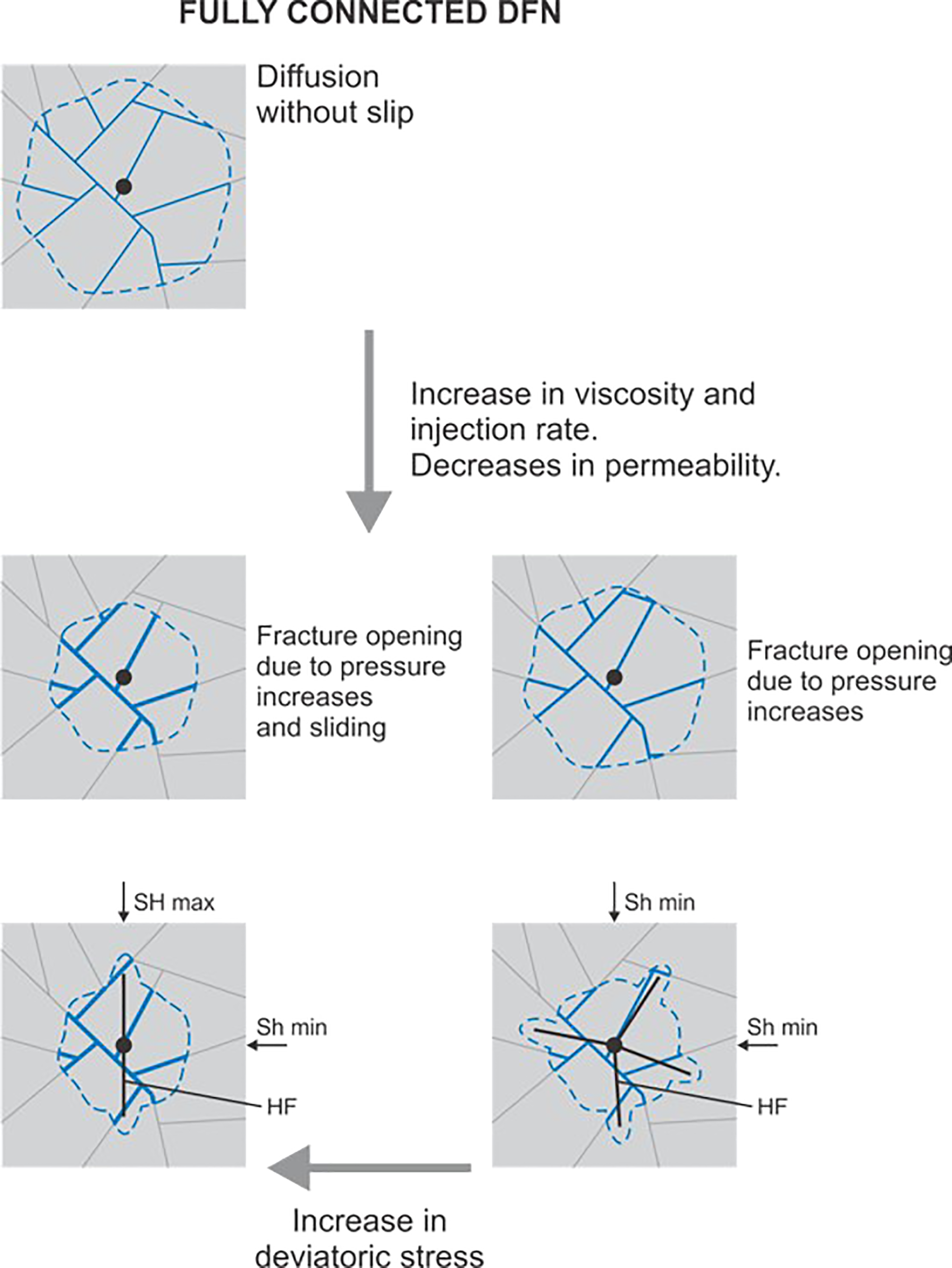
Assuming that the rockmass behaves as a homogeneous continuum, the conceptual model of the rockmass response to fluid injection as a function of two dimensionless parameters is shown in Fig. 1. The pressure changes in the rockmass will always result in elastic deformation. The effective stress, σ′ij, which affects the strength of the rock, is defined as
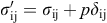
 , is lower than a critical value, the implied pressure changes do not promote inelastic deformations. The critical state is controlled by the hydraulic parameters of equation (2), the stress state (equation (3)) and the rock strength properties (particularly tensile strength). The fluid injection is associated with fluid diffusion into the rockmass and relatively small, elastic deformation (top row in Fig. 1).
Conceptual model of fluid injection in homogeneous, continuous medium
When the dimensionless injection rate exceeds the critical value, and the tensile strength of the rockmass is exceeded, the HF will form and propagate (middle plot in Fig. 1) perpendicular to σ3 (or Sh,min). The direction of the fracture will be well defined if k < 1. As k approaches 1, the orientation of the HF becomes undefined (bottom row in Fig. 1).
The fracture propagation parameters (i.e., the fracture length and width as a function of time) are functions of three dissipative processes: fracturing at the tip, viscous flow of fluid inside the fracture and leakoff of fluid from the HF into the surrounding formation. In typical field applications, dissipative processes owing to fracturing at the tip can be neglected and the fracture propagation can be assumed to be dominated by viscous flow and leakoff. With an increase in the dimensionless injection rate, the leakoff becomes less important and viscosity more dominant (the second and third rows in Fig. 1).
In order to induce permanent changes to the state of the rockmass by fluid injection, it is necessary to cause irreversible deformation or damage in the rockmass. In the case of massive rocks (that can be approximated as homogeneous continua), it is necessary to introduce a HF. However, even the propagation of a HF does not significantly change the stresses in the rockmass. Under fairly general conditions, after a HF develops, the fluid pressure inside the fracture is just slightly greater than the in situ stress perpendicular to the fracture (σ3 or Sh,min). The excess fluid pressure inside the HF relative to σ3, or net pressure, is typically of the order of 1 MPa, which is usually relatively small compared to σ3.
Thus, propagation of a HF, with the exception of the region near the fracture tip, does not significantly change the stress state. Under ideal conditions, the stress perpendicular to the fracture increases insignificantly, while two other principal stresses and orientations of the principal stresses do not change. Furthermore, the stress change owing to fluid pressure increase required for HF propagation is reversible. When the fluid injection is stopped, and the fluid pressure decreases as a result of leakoff and flow-back, the fracture closes with practically no irreversible deformation or stress change. The only way to make the deformation and stress change owing to HF propagation (not associated with shear) permanent is to prop the fracture by injecting proppant during fracture propagation.
In addition, the tensile strength of the rockmass perpendicular to the HF plane is changed. That is the reason that hydraulic fracturing is used for preconditioning of the rockmass and for improvement of fragmentation during block caving mining operations. During preconditioning of the rockmass, a series of parallel HF are created at relatively short spacing (of the order of 1–10 m). The expected stress path during caving operations is such that it will open created HF resulting in fragmentation of the rockmass. However, under conditions when the confining stresses do not change significantly compared to the in situ conditions, hydraulic fracturing in a massive rockmass does not significantly change the rockmass strength after the fluid pressure dissipates and the fracture closes.
Fractured Rockmass
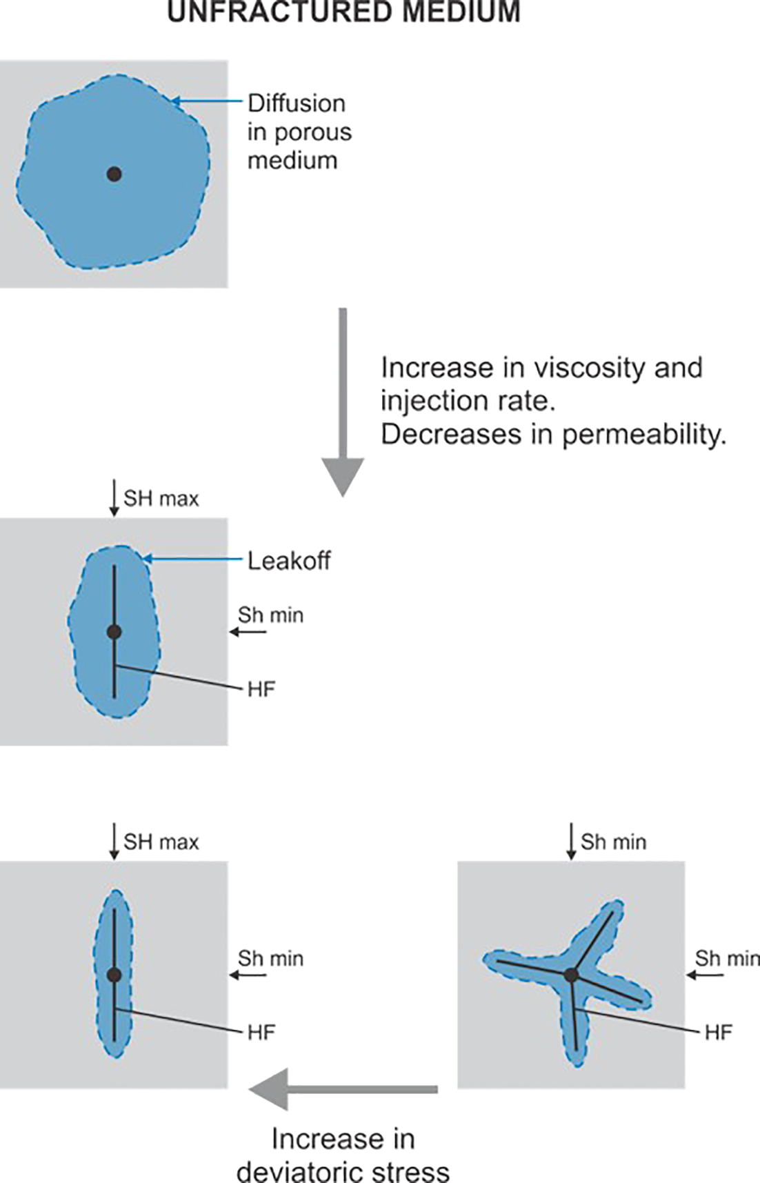
The conceptual model of fluid injection into a fractured rockmass is shown in Fig. 2. For the sake of simplicity, it is assumed that the DFN in the rockmass is fully connected. The main controlling parameters are the same as for the continuum medium, the dimensionless injection rate,  , and the stress ratio, k. However, in the case of a fractured rockmass, because the discrete fractures represent surfaces of weakness, the increase in the pore pressure can cause inelastic, irreversible deformation even before the HF is initiated.
Conceptual model of fluid injection in fractured rockmass
For a relatively small dimensionless injection rate, the pressure changes are also small, such that the normal deformation of pre-existing fractures is small compared to the initial apertures resulting in negligible change in permeability. The injected fluid diffuses into the DFN (top row in Fig. 2). The increase in the dimensionless injection rate at one point induces sufficient pressure change to cause appreciable increase in the aperture of the fractures (owing to reduction in the effective stress) compared to the initial aperture to result in overall permeability change. However, this permeability change is still reversible (i.e., the permeability will decrease as the fluid pressure dissipates).
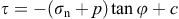
Generally, the condition for fracture slip can be expressed in term of the Coulomb slip condition
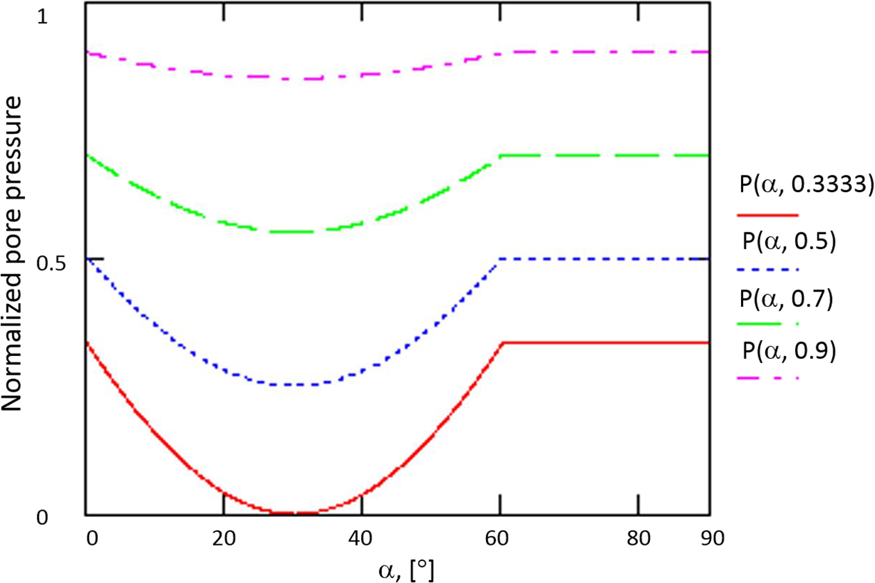
Normalised fluid pressure required to cause a slip on pre-existing fracture or to create a tensile fracture as a function of the angle between the major principal stress and the fracture plane for a range of principal stress ratios between 1/3 and 0.9, friction angle of 30° and zero cohesion
The plots in Fig. 3 indicate that as a function of deviatoric stresses in the rockmass (i.e., the principal stress ratio), the orientation of the pre-existing fractures relative to the orientation of the principal stresses and the fracture shear strength, the pre-existing fractures can slip before the HF is initiated as the pore pressure increases. The horizontal part of the curves in Fig. 3 is the hydraulic fracturing pressure. The conditions for slip are more favourable as the in situ stress ratio decreases (i.e., increasing the in situ deviatoric stress). There is also optimum fracture orientation of 30° (for 30° friction angle), for which the pressure required for slip is a minimum. However, if the angle is greater than 60° (again, for 30° friction angle), slip is not possible (i.e., the HF is generated before the pre-existing fractures slip). The optimum and limiting angles change as a function of the friction angle, i.e., they decrease as the friction angle increases.
Slip on the pre-existing fractures as a result of increase in fluid pressure (i.e., ‘hydro-shearing’) results in two irreversible changes (i.e., even after the injection pressure dissipates) in the rockmass (the right column in the middle row in Fig. 2). The shear stresses that existed on the planes of the pre-existing fractures will be relieved as a result of slip and the stress concentrations will move to the edges of the pre-existing fractures. Depending on the strength of the intact rock those concentrations can also result in extension of pre-existing fractures and potential weakening of the rockmass. Another irreversible change is permanent opening (dilation) of the pre-existing fracture and an increase in aperture. As natural fractures slip, they will dilate as a consequence of fracture surface roughness.
The typical objective of the reservoir stimulation for geothermal projects is to permanently increase the rockmass permeability by hydro-shearing and dilation of pre-existing fractures. The reservoir stimulation for geothermal projects is typically designed to generate pressure sufficient to cause hydro-shearing of pre-existing fractures, but not to induce the HF (the right column in the middle row in Fig. 2).
In a fractured rockmass, similar to homogenous rock, sufficiently large injection pressure will result in initiation and propagation of the HF (the bottom row in Fig. 2). However, in this case (compared to HF propagation in a continuous medium), the trajectory of the HF can be much more complex. In the fractured rockmass, the trajectory of the HF includes both fracturing of the intact rock (‘rock bridges’) and reopening of the pre-existing fractures. As observed in mine-through experiments, HF sometimes propagate through the pre-existing fractures (typically when the intersection angle is close to 90°), but sometimes gets diverted into the pre-existing fractures resulting in offset trajectory. Also, the propagation of the HF in the fractured rockmass is dominated by leakoff into the intersected pre-existing fractures, which can also hydro-shear as a function of fluid pressure increase.
Modelling Example
This modelling example focuses on evaluating the importance of DFN characteristics in a three-dimensional-framework. The statistical parameters that characterise a DFN include the fracture size distribution, orientation distribution and density.
Representation of the Discrete Fracture Network
Three study cases represent different DFNs that have been generated statistically (Fig. 4). The DFN used in this study consists of two fracture sets, each with a given fixed orientation. Both sets are dipping at 75° with dip directions of 45° and 135°. The fracture size follows a power law distribution, which relates the probability of occurrence of a fracture with a size, l, to the negative exponent of the size, i.e., n(l)∞l− α. The value of α is site specific. For 3D fracture systems, the power law exponent is measured to vary in most cases between 2.5 and 4 (Bour and Davy 1998). In this work, the power law exponents of 3.5 (Case 1), 4.0 (Case 2) and 3.0 (Case 3) are used for the three study cases (Fig. 4). The minimum fracture size cutoff of 20 m is used for all three cases. (The minimum fracture size cutoff is determined based on the length scale of the problem analysed.). The maximum fracture size was chosen to be significantly larger than the model domain for Cases 1 and 2, and the maximum fracture size cutoff of 220 m is used for the Case 3. In this three-dimensional study, P32 is used as the measure of the fracture density. P32 is defined as the sum of the areas of all of the fractures divided by the volume of the mapping domain.
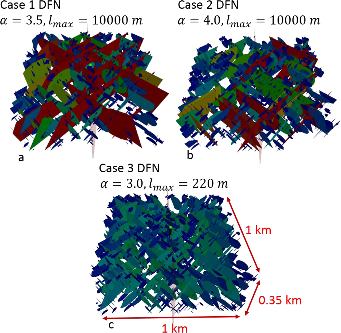
Discrete fracture network (DFN) realisations using a power law distribution with the exponent of 3.5 a; 4.0 b and 3.0 c. Fractures are coloured based on fracture length
The flow characteristics of the DFN are determined by identifying the fracture clusters and evaluating the overall DFN connectivity. A cluster is a group of fractures that are connected to each other. No fracture inside a cluster intersects a fracture belonging to a different cluster. A fully connected DFN is defined as a DFN in which one cluster extends throughout the analysed domain. The fully connected DFN was created through a trial-and-error process, at the critical density that would lead to the formation of one cluster extending throughout the domain.
Considering the computational requirements of the numerical tool used in this study, it was impractical to represent DFNs with the same level of complexity as that observed in the field. Therefore, the DFN realisations were simplified by:
disregarding fractures with a size smaller than a prescribed threshold disregarding the smaller of the two closely spaced, sub-parallel fractures, which are sometimes generated by the Poisson process used for generation of the fracture locations in the synthetic DFN and disregarding clusters that are not connected to any of the following: the main cluster; HF plane or the borehole.
Numerical Approach
The numerical analyses of this study simulated the fully coupled hydro-mechanical response of the DFN to fluid injection. The stimulation phase of EGS is modelled in this work as a demonstration of the numerical approach. During the stimulation phase, fluid is injected into the rockmass to open pre-existing fractures to increase permeability. The model assumption is that fluid flow can only occur within the fractures. The rock blocks between the fractures are modelled as elastic and impermeable. The pre-existing fractures are represented explicitly. They are discontinuities that can open and slip (as governed by the Coulomb slip law) as a function of pressure and total stress.
3DEC can simulate fracture propagation along the predefined planes only. In this study, propagation of pre-existing fractures is disregarded. In order to simulate propagation of an HF, the trajectory of the fracture should be predefined in the model before simulations. In this model, the HF is assumed to be planar, perpendicular to the direction of the minimum principal stress. The two ‘incipient walls’ of the plane of the HF initially are bonded with a strength that is equivalent to a specified fracture toughness. Propagation of the HF corresponds to the breaking of these bonds. The assumption of propagation of the HF along a single planar surface is a simplification. Constraining the path of the HF in the numerical model can result in overestimating the energy required for fracturing. However, in this study, the pressures are such that propagation of the HF is not a primary mechanism, and this simplification is not expected to have a significant effect on the response of the model.
Figure 5 shows the geometry and set-up of the 3DEC model. The fluid is injected along the vertical open-hole completion segment of a borehole at a constant rate. The open-hole completion segment lengths of 20, 60 and 350 m were used for all three cases. The core part of the model containing the DFN is embedded into a larger domain with a regular network of pipes with a permeability equivalent to that of the core region. The linear dimensions of the full model are twice as large as those of the core part. The model core measures 1000 × 1000 × 350 m. The state of stress is assumed to be anisotropic, with the maximum principal horizontal stress equal to the vertical stress and the minimum principal horizontal stress equal to half of the vertical stress. The selected magnitudes of the initial stresses are based on typical depths of EGS.
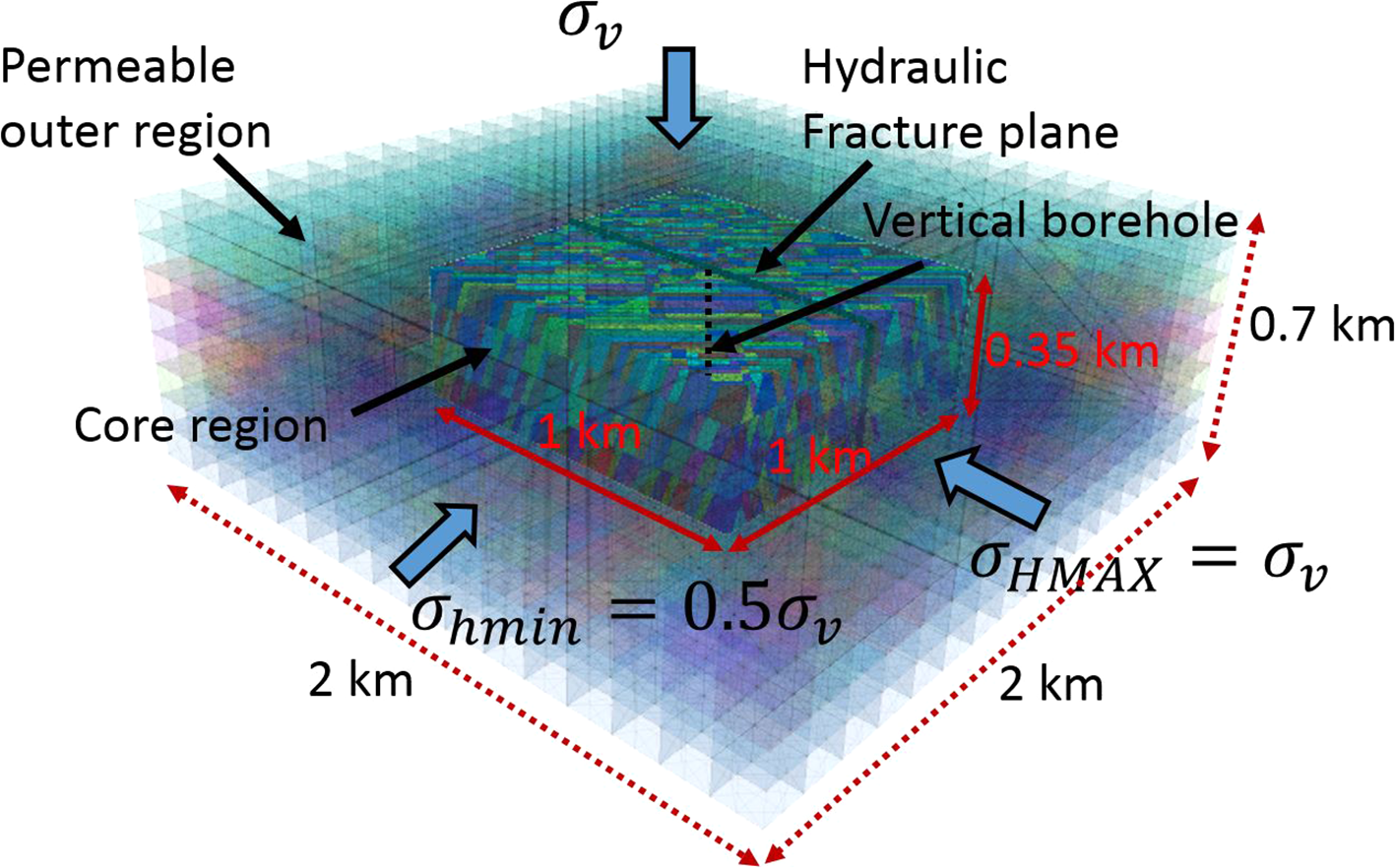
Geometry and model set-up
The applied injection rate is 0.07 m3 s− 1 or 70 kg s− 1. This rate is approximately equal to 26.4 bpm (barrels per minute). It is assumed that the pre-existing fractures are already open and conductive with a uniform aperture for each fracture set. The primary and secondary fracture sets are assigned an initial aperture of 3 × 10− 5 m, and 1 × 10− 5 m, respectively. The failure criterion of the pre-existing fractures is defined by the Coulomb slip law, with zero cohesion, a friction angle of 30° and a dilation angle of 7.5°.
Results
In this work, the response of the DFN to fluid injection was evaluated with regard to fracture size distribution. In addition, the effect of the borehole length was investigated for different DFN realisations. The three DFNs used in this study (Fig. 4) are fully connected. However, the DFN realisations have different length exponent, α, and a maximum fracture length, lmax. Both the primary and secondary fracture sets are oriented favourably for slip (i.e., the fluid pressure required to cause slip on the fractures is less than the minimum principal stress).
Qualitative and quantitative results are correlated to the exponent α of the fracture size distribution and the probability of having large fractures relative to the domain size. Larger α results in a narrower range of fracture sizes with a higher frequency for fractures with the length close to lmin. For example, very large values of α lead to a constant fracture size equal to lmin. However, it should be noted that Case 3 has the smallest α, but the maximum fracture size is capped to 220 m. Thus, the DFN has a fairly narrow fracture size distribution with both the mean and frequency of large fractures much smaller than those of the same distribution with uncapped lmax. In these analyses, injection pressure remains below the HF pressure.
Figures 6 and 7 show the evolution of the apertures for Cases 1 and 3, respectively. In both cases, the borehole length was 20 m with no fracture intersecting the borehole. Figures 6 and 7 indicate that in both cases a small propagation of HF was required to reach the closest pre-existing fractures. As soon as the fluid reached the pre-existing fractures at early stages of the fluid injection, the HF stopped growing.
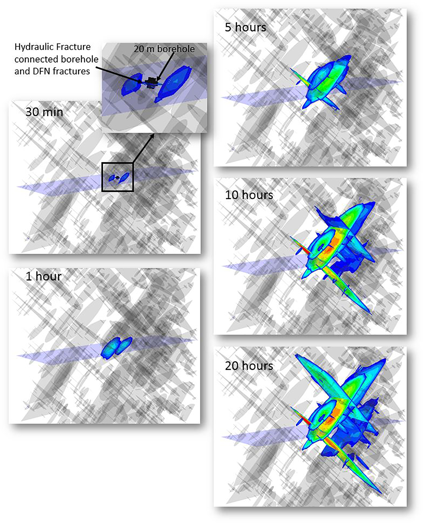
Evolution of apertures in Case 1 (α = 3.5) with the borehole length of 20 m (red in aperture plots equals 1 mm)
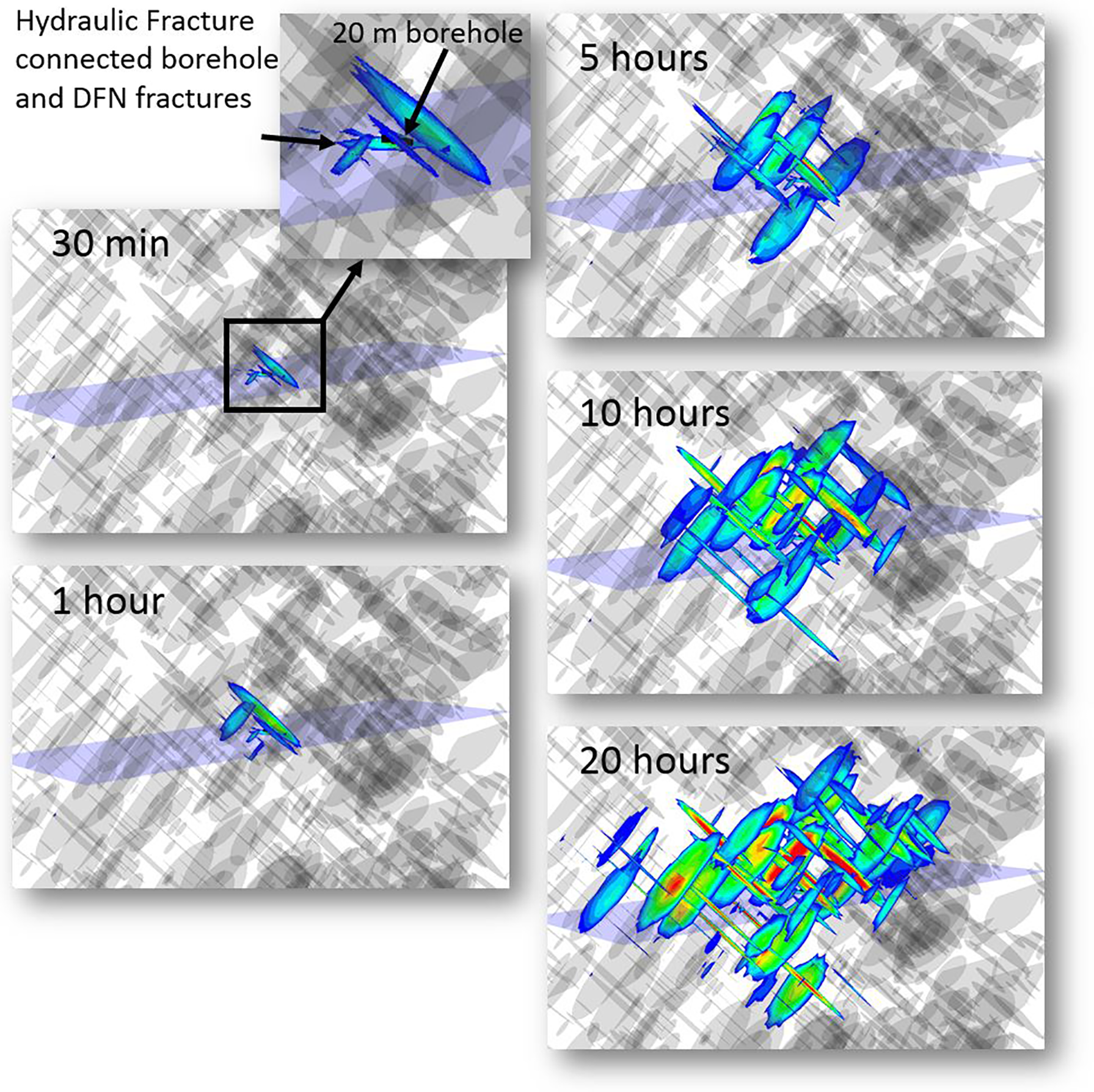
Evolution of apertures in Case 3 (α = 3 and capped fracture size) with the borehole length of 20 m (red in aperture plots equals 1 mm)
Comparing the results of different borehole lengths for Case 3 (Fig. 8) indicates that there is no significant HF growth in the 20 h of injection for all three cases of the borehole length. Higher pressures are observed in the case of the smaller borehole length taking into account that all fluid flow is distributed along a smaller borehole volume. Results are qualitatively similar for all cases of borehole length, even though slightly different sets of fractures are stimulated. Despite the different borehole lengths, the same volume of the fluid was injected in all of these cases. The presented results indicated that the shear-stimulated fracture area depended on the volume of the injected fluid and were not affected by the borehole length.
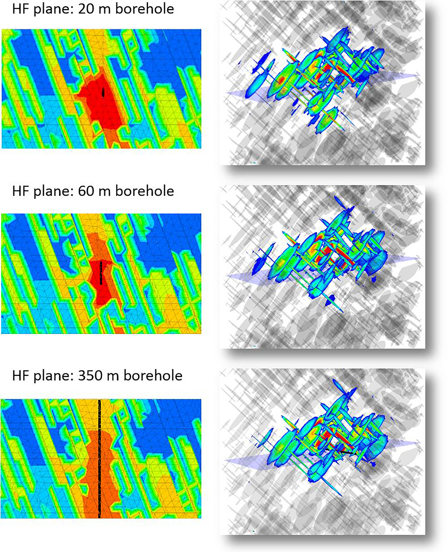
Fluid pressure contours (left) and aperture contours (right) after 20 h injection in Case 3. Red in pressure plots equals to 32 MPa, red in aperture plots equals 1 mm
In contrast to Cases 1 and 3, more significant HF growth is observed in Case 2 (Fig. 9). Different patterns of HF propagation in three cases of the borehole lengths provide fluid access to different fractures causing variation in aperture contours (Fig. 9, right).
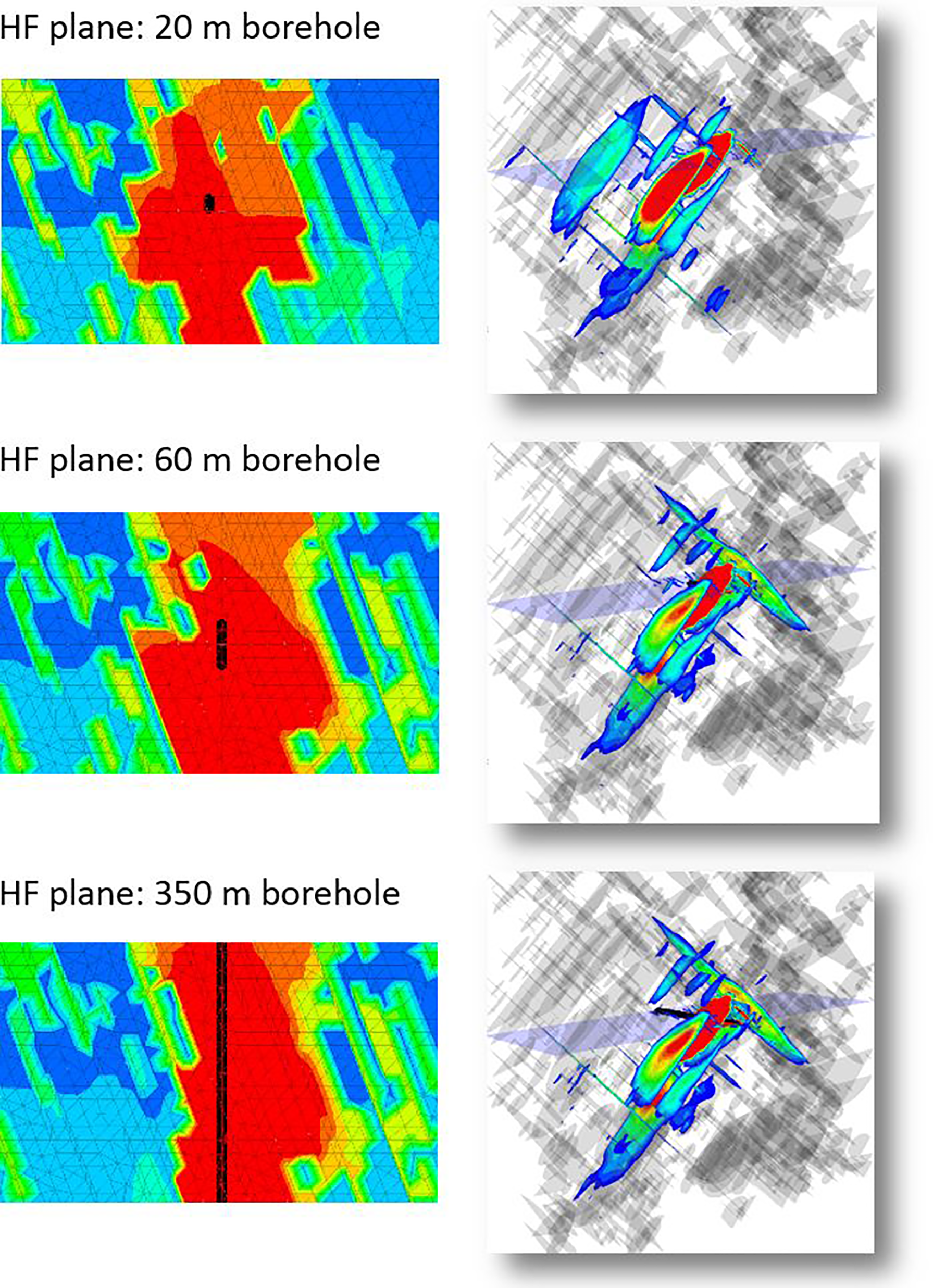
Fluid pressure contours (left) and aperture contours (right) after 20 h injection in Case 2. Red in pressure plots equals to 32 MPa, red in aperture plots equals 1 mm
Qualitative comparison of models in Cases 1, 2 and 3 is given in Fig. 10, which shows slip contours after 20 h of stimulation for the cases with borehole length of 60 m. Figure 10 suggests that fluid flow and shape and location of stimulated volume in the rockmass depends strongly on the geometrical parameters of the DFN. The Case 3 model, in which the DFN is characterised by a narrower range of fracture size distribution with a maximum fracture length smaller than the DFN region, experiences more uniform, even and symmetrical shear-stimulated volume when compared to Cases 1 and 2 DFNs. Cases 1 and 2 indicate highly asymmetrical shapes of stimulated volumes in regard to a borehole. Therefore, the presence of large fractures in the network causes asymmetric irregular shapes of the stimulated volume and localisation of flow.
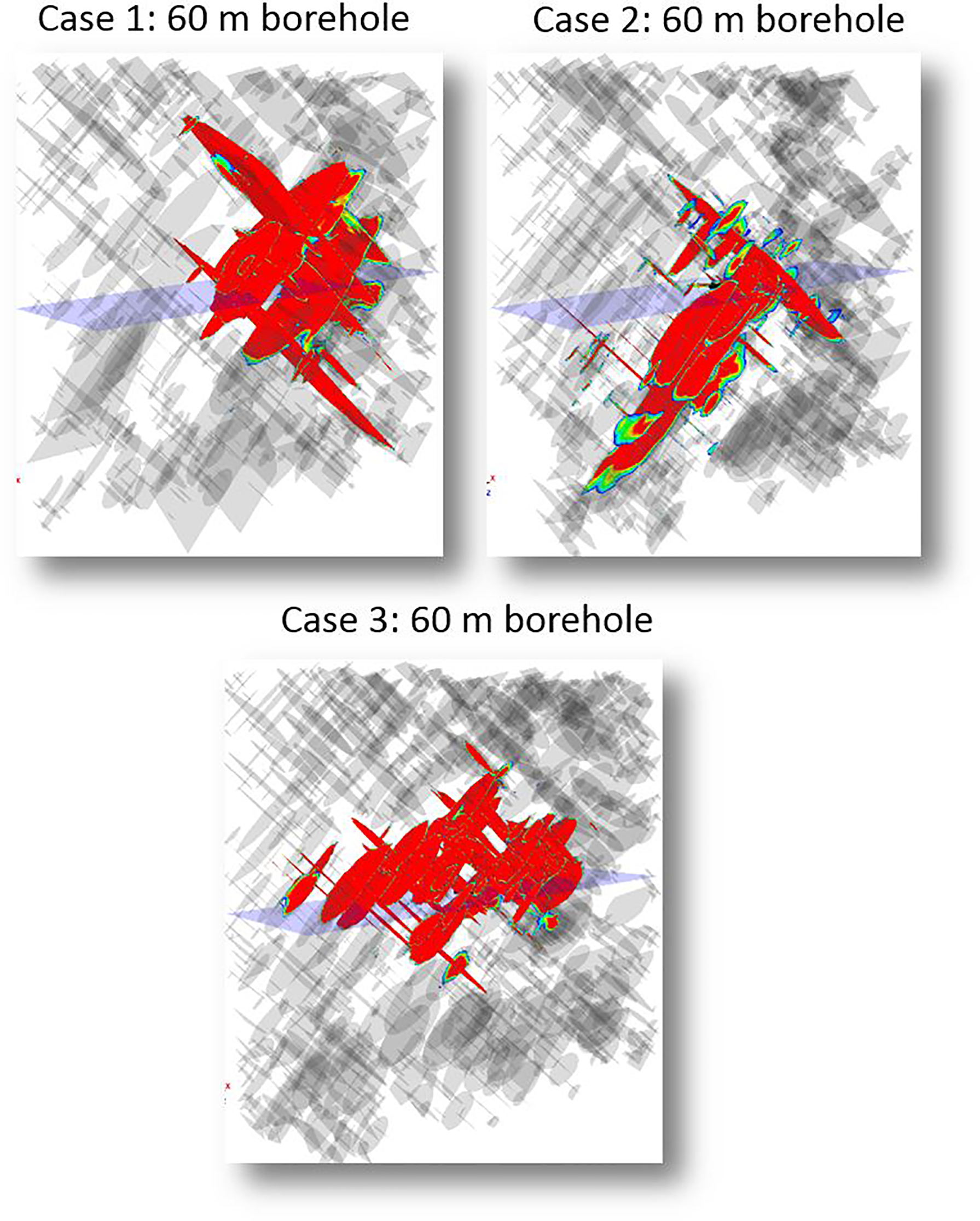
The effect of fracture size distribution: slip on fractures after 20 h of injection (maximum of 1 mm)
Comparing the graphs of the shear-stimulated surface area indicates that the smallest area was stimulated in Case 2 (Fig. 11), the case that shows the largest growth of the HF. The HF accommodates some of the injected fluid, resulting in slower propagation of the pressure front and smaller stimulated volume. In addition, comparing the differential stress changes (Fig. 12) it is clear that Case 2 models experienced the largest drop of the differential stresses that reduce the possibility of shearing along the fractures (differential stresses are averaged over 100 m distance from a borehole).
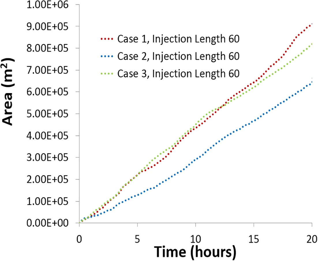
The effect of fracture size distribution: history of shear-stimulated area
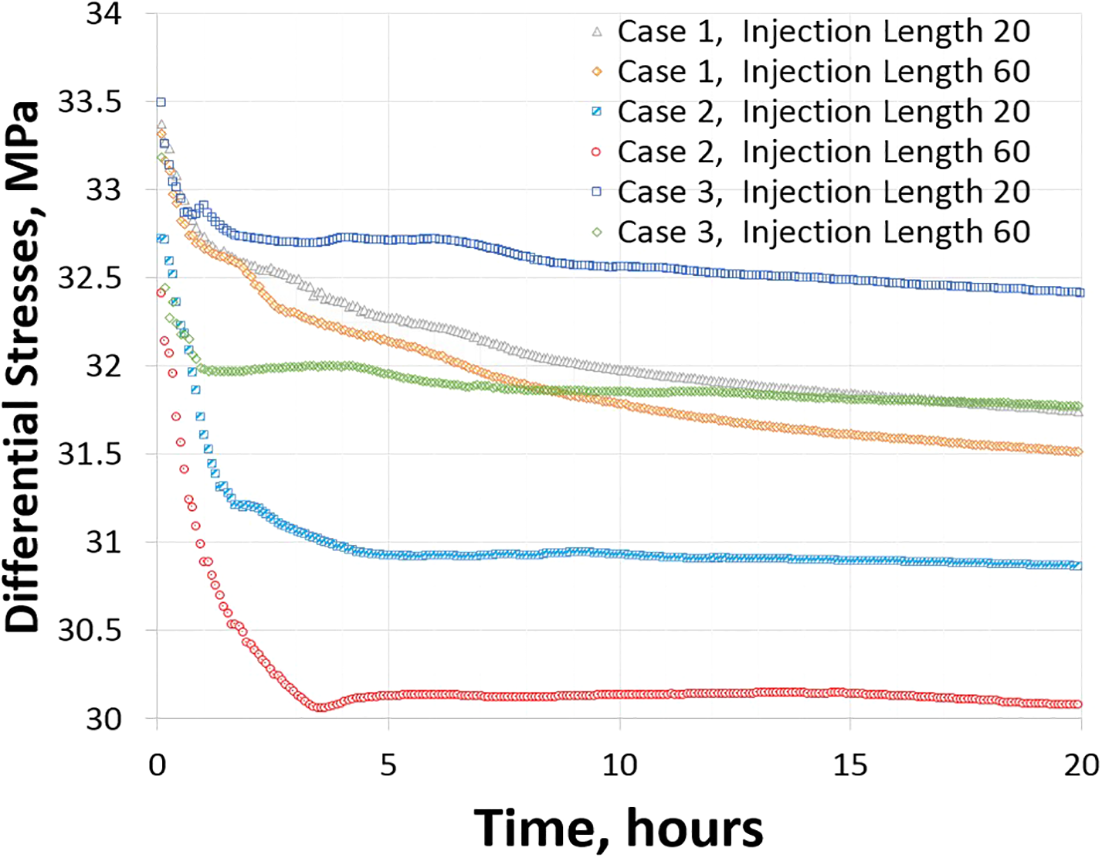
Differential stress changes owing to fluid injection
Discussion and Conclusions
Hydraulic fracturing performed for mining and oil and gas industries results in propagation of a fracture in an opening mode. However, if the rockmass contains pre-existing fractures, depending on the magnitudes of the principal stresses, orientation of pre-existing fractures and their shear strength, the injection can pressurise them and sufficiently reduce the effective stress to cause shearing at the pressure below that required for hydraulic fracturing (i.e., the pressure lower than the magnitude of the minimum principal stress). Although it is conjectured that shearing can be caused by change in total stresses only (i.e., while fractures are still ‘dry’), the literature seems to indicate that shearing occurs only if the fluid enters the fracture and pressurises it.
In most mining, and oil and gas HF treatments, fluid injection rates are sufficiently high that an opening-mode fracture is initiated and propagated; however, some fluid is lost into cross-cutting fractures and this leads to some shearing on them with associated microseismicity. Pine and Batchelor (1984) analysed shear fracture growth associated with injections of water into the fractured Carnmenellis granite near Cornwall, UK. If the directions of stresses do not align with the natural fracture directions, the critical pressure for shear fracturing can be considerably less than the pressure for opening mode HF extension (Fig. 3; van As and Jeffrey 2000).
During cave inducement (i.e., preconditioning in the cave-induced stress field) for the cave mining, the in situ stress field is modified by the cave. The least principal stress becomes perpendicular to the boundary in close proximity to the boundary. Holes orthogonal to the cave boundary, as a result, are aligned approximately with the minimum stress direction. In these holes, HFs can initiate at a natural fracture or flaw that cuts across the borehole axis. If an initiation point does not exist in the borehole, it is common for a HF to initiate as an axial fracture along the borehole wall at a position controlled by the stress concentrations (Jeffrey et al. 2009).
The effect of the stress field and the natural fractures on crossing interactions may lead to non-circular fracture shapes. In many cases the fracture grows along a shear zone (most probably owing to singular permeability of brittle shear zone or because of the strength anisotropy developed in ductile shear zone) and along natural fractures. Significant fracture offsets can occur owing to shear zones; minor offsets occur frequently as the fracture grows through the natural fractures. Branched sections also can form during fracture propagation. In general, it is suggested that hydraulic fracturing might weaken the rockmass (certainly the tensile strength in the direction perpendicular to the induced fracture surfaces) enhancing caveability and improving fragmentation.
Nelson et al. (2007) state that the influence of geology on HF stimulation has been well documented in the literature. Pre-existing geological weaknesses (e.g., natural fractures, joints, faults and bedding planes) have been shown to open and reactivate during fracture stimulation operations. As discussed by Kaieda, Sasaki and Wyborn (2010), many cases (e.g., Ogachi, Hijiori and Cooper Basin) have demonstrated relatively low seismic activity until the injected water extended beyond the boundaries of the previously injected volume. (The intensity of seismic activity increased when the fluid reached the unstimulated rockmass.) This is thought to be owing to stress release (caused by permanent changes to the natural fracture network) attributable to previous water injection. The water volume injected and the seismically activated area of each site showed linear correlations, but the slope of this relationship differs by site. These differences are thought to be strongly dependent on the regional joint system and stress conditions.
The response of pre-existing fracture networks to fluid injection, including potential HF propagation, has been investigated in the numerical example by explicit representation of the fractures in a three-dimensional framework. This example presents some results of a study focused on understanding of the complex processes involved in DFN stimulation and hydraulic fracturing by fluid injection. The hydro-mechanical response of pre-existing fracture networks to fluid injection has been studied with respect to some of the DFN characteristics, i.e., fracture size distribution and borehole length. The results are summarised as follows.
Fluid flow in a rockmass depends on the DFN characteristics, including shape and location of the stimulated region. In a fully connected DFN, HF propagation results in less efficient DFN stimulation. For fully connected DFNs, under conditions favourable for the development of hydro-shearing, borehole length may not influence the DFN shear-stimulated surface area. DFN characterised by a narrower range of fracture size distribution with a maximum fracture length smaller than the model domain, experiences more uniform and symmetrical fluid percolation and DFN stimulation in regard to the borehole. The presence of large fractures can cause localised flow and asymmetrical shapes of stimulated volume. Asymmetric responses to fluid injection are frequently observed in recorded microseismic data.
The outcome of the numerical experiment presented in this paper suggest that, everything else being equal, the characteristics of the DFN has a strong influence on the shape of the stimulated volume and the activated facture area. Such important findings should be tested with experimental data. The most promising approach in that matter are medium scale injection experiments in underground laboratory settings with a dense, multi-parameters (stress, deformation, micro-seismicity, fluid pressure) monitoring system and high resolution rockmass characterisation data (Kaiser, Valley, Dusseault and Duff 2013). These experiments should be executed at various locations in order to cover significantly different DFN characteristics and tectonic settings (stress regime).
The datasets generated by these experiments will be invaluable to calibrate, verify and improve numerical models such as the ones presented in this paper. This will in turn increase the predicting power of such models. However, one needs to acknowledge that if the results obtained in this paper hold true, small modifications in the fracture network may induce significant changes in the model prediction. In practical applications, it is unlikely that sufficient details on the in situ conditions, particularly on the detailed fracture network characteristics, will be known ahead of time at the design stage. This however emphases the importance of collecting quality datasets on the fracture network characteristics, possibly beyond current standard practices, when hydraulic injections are to be used as a rockmass conditioning tool. This also implies that purely deterministic approaches are likely to fail and meaningful results can be obtained only if such modelling approaches are embedded in a robust stochastic framework.
In addition, the details of the model output are likely to be meaningless, as they will depend on details of the fracture network that will remain beyond the resolution of our characterisation techniques. More global indicators, like the stimulated area used in this paper, are however meaningful outputs with important practical implications (e.g., the efficiency of heat extraction in an EGS will depend directly on such parameter). Numerical experiments, such as the ones presented in this paper or more comprehensive ones to be performed, are thus very valuable to determine which are the key parameters influencing the response of the rockmass and the overall efficiency of hydraulic injections. These results will help to guide optimal data collection required to design such hydraulic injections.
Acknowledgements
The authors acknowledge the financial support of the Centre for Excellence in Mining Innovation and Sandia National Laboratories for this work. Richard Brummer and anonymous reviewers are thanked for their helpful comments that improved this paper.
This paper was originally presented at the first International Conference on Discrete Fracture Engineering (DFNE 2014) (19–22 October 2014, Vancouver, Canada) and has subsequently been revised and extended before consideration by Mining Technology.