
Abstract
In this study, hybrid aluminum (Al) matrix composites reinforced with copper-coated carbon fibers and SiC particles (SiCp-Cu@CF/Al composites) were manufactured by the powder metallurgy method. With the carbon fiber mass fraction fixed at 1 wt%, the effect of SiC particle mass fraction on the microstructure and properties of the composite was systematically investigated. The results indicated that with the addition of 3 wt% SiC particles, the SiCp-Cu@CF/Al composite exhibited a hardness of 73.47 HB and a tensile strength of 344.38 MPa, which were 30.6% and 22.1% higher than those of the copper-coated carbon fiber reinforced aluminum matrix (Cu@CF/Al) composite, respectively. Meanwhile, the composite demonstrated an average friction coefficient of 0.4526 and a wear rate of 0.93 × 10⁻² mm3/N·m, representing reductions of 42.7% and 66.6%, respectively. Carbon fibers enhanced the tensile strength primarily through axial load-bearing, while SiC particles improved the hardness and wear resistance via dispersion strengthening and grain refinement. The synergistic effect of these two reinforcements, aided by a graded stress distribution at the interface that inhibited crack propagation, led to a complementary improvement in the overall mechanical and tribological properties. This work provides a systematic understanding of the synergistic strengthening and wear-resistance mechanisms of SiCp-Cu@CF/Al composites fabricated by powder metallurgy, and identifies an optimized SiC particle content for achieving balanced mechanical and tribological performance.
Keywords
Introduction
Composite materials have evolved from conventional single-phase structural materials to fiber, particle, and hybrid-reinforced systems designed for multifunctional performance.1,2 Among them, aluminum matrix composites (AMCs) have attracted considerable attention because of their outstanding mechanical properties, including high specific strength and specific modulus. Owing to these advantages, AMCs have emerged as important lightweight structural materials and have been widely used in aerospace, the nuclear sector, and the automobile industry.3–5 In early composite systems, fibers were mainly introduced to improve load-bearing capacity and specific strength, whereas particulate fillers were commonly used to enhance hardness, dimensional stability, thermal resistance, and wear resistance.1,6 Nevertheless, the relatively poor wear resistance and inadequate strength-ductility synergy of AMCs still hinder their application in specific engineering fields.7,8 To address these limitations, hybrid reinforcement strategies that combine complementary reinforcing phases have shown significant promise for improving the comprehensive performance of AMCs through synergistic strengthening and toughening mechanisms.9,10 Recent studies have further demonstrated that the mechanical, thermal, and tribological properties of composites are strongly influenced by the type, morphology, scale, distribution, and surface condition of reinforcements.2,6,11 In particular, micro/nano fibers, ceramic particles, and surface-coated nanoparticles can improve stress transfer, interfacial bonding, friction stability, and wear resistance.6,11,12 These findings provide important guidance for the design of metal matrix composites, where interfacial compatibility and multi-scale reinforcement architecture are critical for achieving balanced mechanical and tribological properties.
Wang et al. 13 developed micro/nano Al2O3 hybrid FeCoNiCrMn HEA particle reinforced AMCs through the process of microwave sintering. The hardness, compressive strength, and yield strength of the 2% nano-Al2O3 sample were measured at 109.7 HV, 560.7 MPa, and 286.5 MPa, respectively. In comparison to the single HEA, the strength exhibited increases of 70.9%, 94.7%, and 98.5%, respectively. Su et al. 14 fabricated a 6013 aluminum matrix composite dual-reinforced with carbon nanotubes (CNTs) and SiC particles (SiCp) via powder metallurgy. The composite demonstrated an ultimate tensile strength of 666.21 MPa and an elastic modulus of 89.39 GPa, surpassing the CNT/6013Al and SiC/6013Al composites by 22.7% and 112.5%, respectively. Guo et al. 15 developed hybrid reinforced aluminum matrix composites consisting of SiC and graphite particles (SiC-Gp/Al composites) using the powder metallurgy technique. The tribological properties of hybrid composites were examined, revealing that the friction coefficient of SiC-Gp/Al composites was markedly lower than that of single SiCp reinforced Al matrix composites.
Carbon fibers (CFs) are extensively utilized as a reinforcement phase in a range of matrices, such as metal, polymer, and ceramic, for the fabrication of composites due to their impressive strength, low density, and minimal coefficient of thermal expansion.16–19 Lv et al. 20 produced a CF/Al composite using squeeze casting, which achieved the maximum tensile strength of 169 MPa while maintaining an elongation of 4.2%. Nevertheless, the strength enhancement from carbon fibers comes at the expense of material embrittlement and an increased wear rate due to fiber pull-out during wear. 21 Owing to their elevated hardness, outstanding wear resistance, and thermal stability, SiC particles are also widely used as a reinforcement phase to enhance AMCs. Ye et al. 22 fabricated a SiC/Al composite using pressure infiltration, which achieved a maximum yield strength of 643 MPa. However, its elongation was not reported. It is well established that while SiC can significantly enhance the strength of composites, it often leads to a deterioration in their ductility and toughness. 23 Carbon fibers and SiC particles hybrid reinforced aluminum matrix composites have drawn significant research interest in recent years due to their great potential for achieving a balanced multi-property profile and overcoming the limitations of single-reinforcement composites.24–26
In this study, we fabricated hybrid Al matrix composites reinforced with CFs and SiCp using powder metallurgy techniques. Furthermore, to mitigate the detrimental interfacial reaction between CFs and the aluminum matrix during composite preparation, copper coatings were applied to the surface of the CFs using an electroless plating technique. Although carbon fibers and SiC particles have both been widely used as reinforcements in aluminum matrix composites, most previous studies have focused either on single-reinforcement systems or on limited hybrid systems mainly involving mechanical, thermal expansion, or damping properties. The coupled mechanical and tribological behavior of copper-coated carbon fiber and SiC particle hybrid reinforced Al matrix (SiCp-Cu@CF/Al) composites fabricated by powder metallurgy has not been sufficiently investigated. In particular, the optimum SiC particle content under a fixed carbon fiber content, the individual contribution of each reinforcement, and the synergistic strengthening/wear-resistance mechanism remain unclear. Therefore, this work aims to clarify the microstructure-property relationship and the cooperative strengthening and wear-resistance mechanisms of SiCp-Cu@CF/Al composites.
Experimental
Raw materials
In this study, the carbon fibers (CFs), SiC particles (SiCp) and pure aluminum powders were used as raw materials. CFs (purity ≥99.9%, diameter: 7 μm, density: 1.76 g/cm3) were supplied by Weihai Guangfu Composite Material Co., Ltd. SiCp (purity ≥99.9%, average particle size: 400 nm, density: 3.2 g/cm3) were purchased from Beijing Zhongke Yannuo New Material Co., Ltd. Pure aluminum powder (purity ≥99.9%, average particle size: 1 μm) was provided by Beijing Yijin New Material Technology Co., Ltd.
Fabrication of composites
The hybrid aluminum (Al) matrix composites reinforced with copper-coated carbon fibers and SiC particles (SiCp-Cu@CF/Al composites) were produced via the powder metallurgy method, as illustrated in Figure 1. Firstly, to improve the wettability between the CFs and aluminum matrix, a copper coating was deposited on the CF surfaces via an electroless plating process. Surface pretreatment was a crucial step in the electroless copper plating of the CFs. The CFs were subjected to heating in a muffle furnace at 150°C for 8 min to eliminate the sizing agent, followed by acidification in 65 wt% nitric acid. Subsequently, they were sequentially immersed in SnCl2 and PdCl2 solutions for sensitization and activation, respectively. After completing the aforementioned steps, the CFs and a pre-prepared plating solution were placed in a water bath and allowed to react for 8 min. The 1 wt% copper-coated carbon fiber (Cu@CF), different mass fractions of SiCp (1, 3 and 5 wt%) and Al powder were combined for 1 h at 300 rpm in argon-protected stainless-steel tank. The uniformly mixed composite powder was first cold pressed in a graphite mold under 40 MPa for 30 min to obtain green compacts. The green compacts were then placed in a fast hot-pressing sintering furnace (FHP-828, Haatn, China). Before heating, the chamber was evacuated to 10-2-13-2 Pa. The temperature was increased from room temperature to 600°C at a heating rate of 50°C/min. When the temperature reached 600°C, an axial pressure of 35 MPa was applied and maintained for 8 min. After sintering, the specimens were cooled to room temperature in the furnace under vacuum protection. Schematic diagram of the preparation process of SiCp-Cu@CF/Al composites.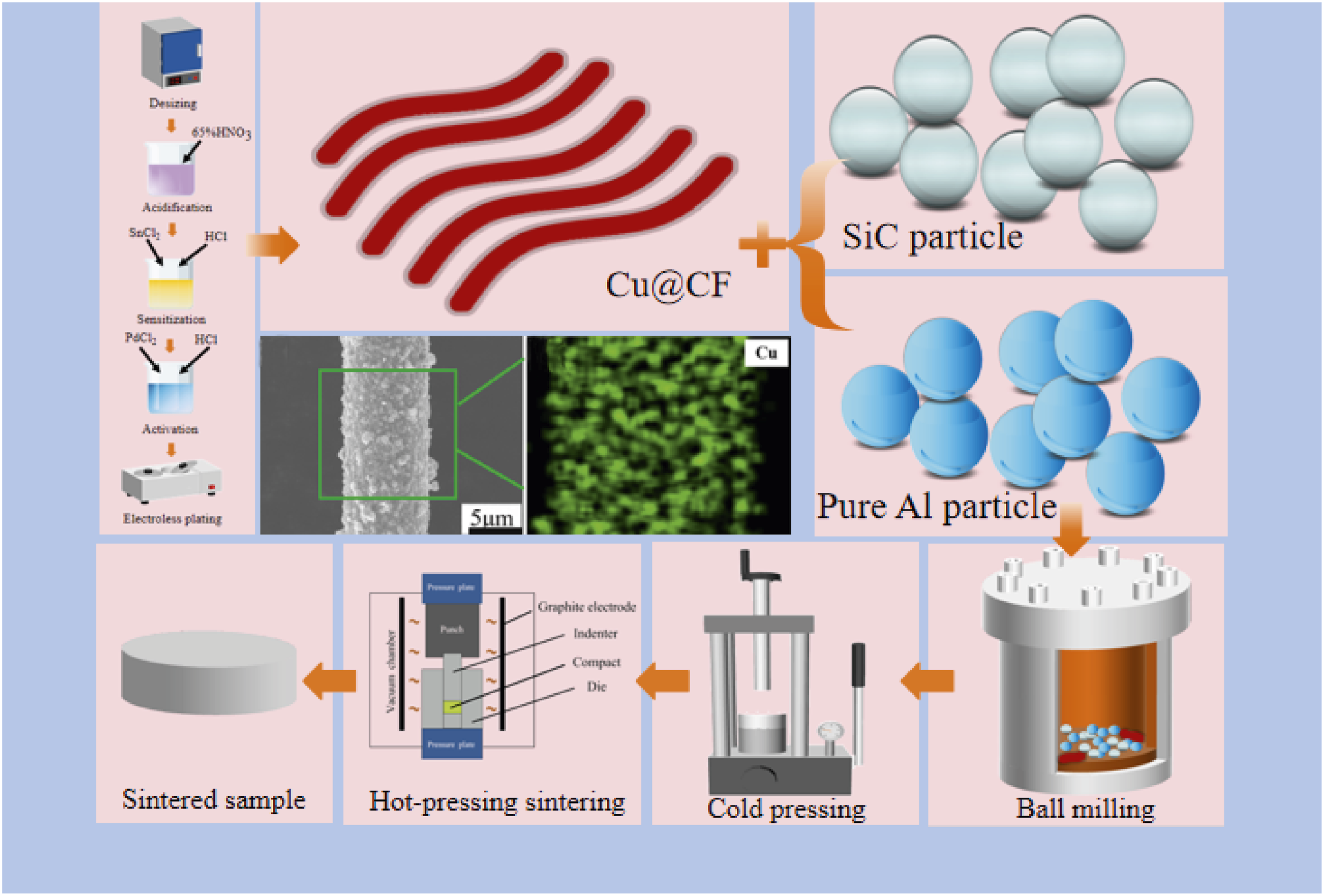
Figure 2 presents a photograph of the as-sintered samples. For each composition, at least five disk-shaped samples with a uniform diameter of 40 mm and a thickness of 2 mm were prepared. The sintered compacts were machined into specimens of various dimensions using a wire electrical discharge machining (DK7740, Huadong Automation, China) for microstructure characterization and property testing. Specimens for microstructure characterization, density measurement, and hardness testing were rectangular with dimensions of 5 mm × 5 mm × 2 mm. Dog-bone-shaped specimens were used for tensile tests, with a gauge length of 10 mm, a gauge width of 2 mm, and a thickness of 2 mm. Wear test specimens were rectangular with dimensions of 10 mm × 10 mm × 2 mm. To ensure repeatability, the hardness of each sample was measured at no fewer than six different locations. Tensile and wear tests were repeated at least five times for each composition. The mean values and standard deviations were calculated and are presented as error bars in the figures. Photograph of the sintered disk-shaped composite specimens used in the experiments.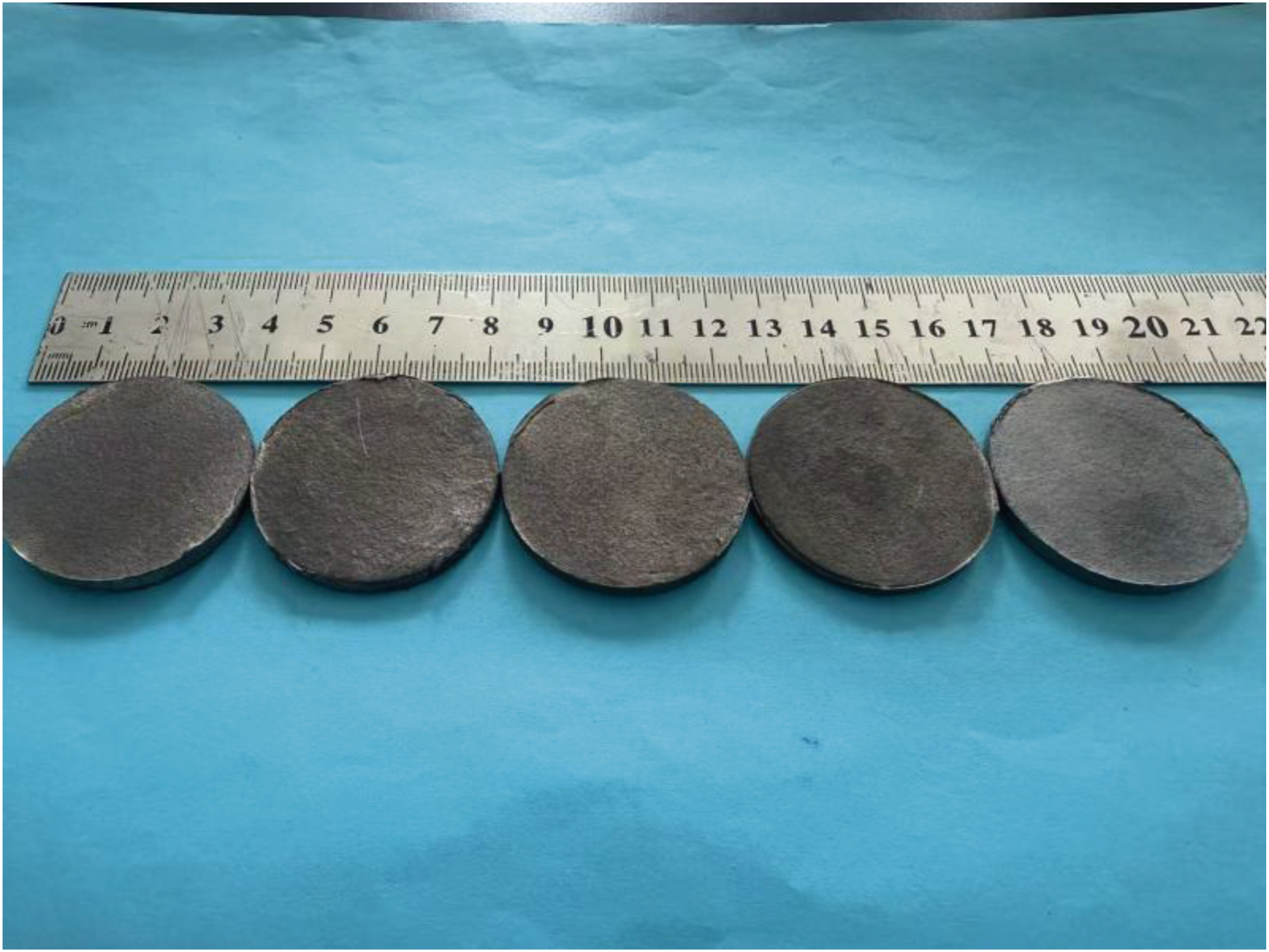
Characterization
A field emission scanning electron microscope (FESEM, Supra55, Zeiss, Germany) equipped with an energy dispersive X-ray spectrometer (EDS) was utilized to examine the microstructure of the specimens. Grain size and phase distribution were evaluated using electron backscattered diffraction (EBSD, NordysMax, Oxford, UK) at a voltage of 20 kV, employing a step size of 0.11 μm. The phase compositions of the composites were analyzed using X-ray diffraction (XRD, Dmax/2500PC, Rigaku, Japan) within the 2θ range of 20-100° at a scanning rate of 5°/min.
The hardness was evaluated with a Brinell hardness tester (310HBS-3000, Huayin, China) with a load of 500 N applied for 15 s. Hardness tests were conducted at a minimum of six distinct sites for each sample, and the average value was documented. The tensile strength of the composites was evaluated using a universal testing machine (5892, Instron, USA) at a strain rate of 0.1 mm⋅min−1 under ambient temperature conditions.
The multifunctional friction and wear tester (MFT-5000-H, Rtec instruments, USA) was employed to perform friction and wear experiments on the surfaces of sintered samples. The wear-test specimens were machined into 10 mm × 10 mm × 2 mm. For each composition, five independent wear tests were performed under the same conditions, and the average friction coefficient and wear rate were reported together with the standard deviation. A GCr15 bearing steel ball with a diameter of 6.35 mm and a hardness of 60 HRC was used as the antagonist material during the dry sliding wear test. The dry sliding wear tests were conducted using a reciprocating sliding configuration with reference to ISO 7148-2:1995. Before conducting the experiment, a 0.25 μm alumina colloidal suspension, containing a polishing agent, was utilized to carefully polish the sample surface. The experiments were carried out over a period of 20 min at room temperature, with a load of 25 N applied and a sliding speed maintained at 40 mm/s. A normal load of 25 N and a sliding speed maintained at 40 mm/s were selected to provide a moderate dry sliding condition. Under such a condition, measurable wear tracks can be obtained without causing catastrophic surface damage or severe plastic deformation of the sintered composites. Menachery et al.
27
tested CF-reinforced AA7050 composites at 10, 25, and 40 N and found that the mass loss under 10 and 25 N was relatively stable, whereas a marked increase occurred at 40 N. This indicates that 25 N can be regarded as an intermediate condition before severe wear becomes dominant. The laser confocal microscope (LSM-700, Zeiss, Germany) was utilized to acquire the 3D profile and the cross-section curve of the worn surface. The wear volume was obtained from the three-dimensional wear profiles measured by laser confocal microscopy. To reduce local measurement error, three cross-sectional profiles at different positions of each wear track were measured, and the average wear volume was used for calculation. The specific wear rate was calculated using the following equation:

Results and discussion
Microstructure analysis and density of composites
Figure 3 demonstrates the microstructures of the SiCp-Cu@CF/Al composites with different SiCp mass fractions. A diagrammatic representation of the sample is presented in Figure 3(a), where CFs were randomly allocated in the aluminum matrix, while the smaller SiCp filled the gaps between the CFs and the aluminum matrix, effectively reinforcing the weak interfacial regions. This three-dimensional hybrid reinforcement structure can be analogized to a concrete system: the aluminum matrix acts as the cement, the CFs resemble steel rebars, and the SiCp serve as aggregates. The synergistic interaction among these three components significantly enhanced the overall performance of the composite. Figure 3(b) and (c) correspond to the SiCp-Cu@CF/Al composites with SiCp mass fractions of 1 wt.% and 3 wt.%, respectively. In these images, the black areas represent CFs, the white areas indicate SiCp, and the gray areas correspond to the aluminum matrix. The SiCp were uniformly dispersed in the aluminum matrix and formed a well-integrated composite structure with the CFs. This uniform distribution facilitated effective stress transfer, thereby enhancing the mechanical properties of the material. However, when the SiCp mass fraction was increased to 5 wt.%, Figure 3(d) revealed obvious particle agglomeration in localized regions. Furthermore, in the magnified view of Figure 3(e), clusters of SiCp forming distinct defective areas could be clearly observed. Microstructures of SiCp-Cu@CF/Al composites with different SiCp mass fractions: (a) schematic diagram of the composite sample, (b) 1 wt.%, (c) 3 wt.%, (d, e) 5 wt.%.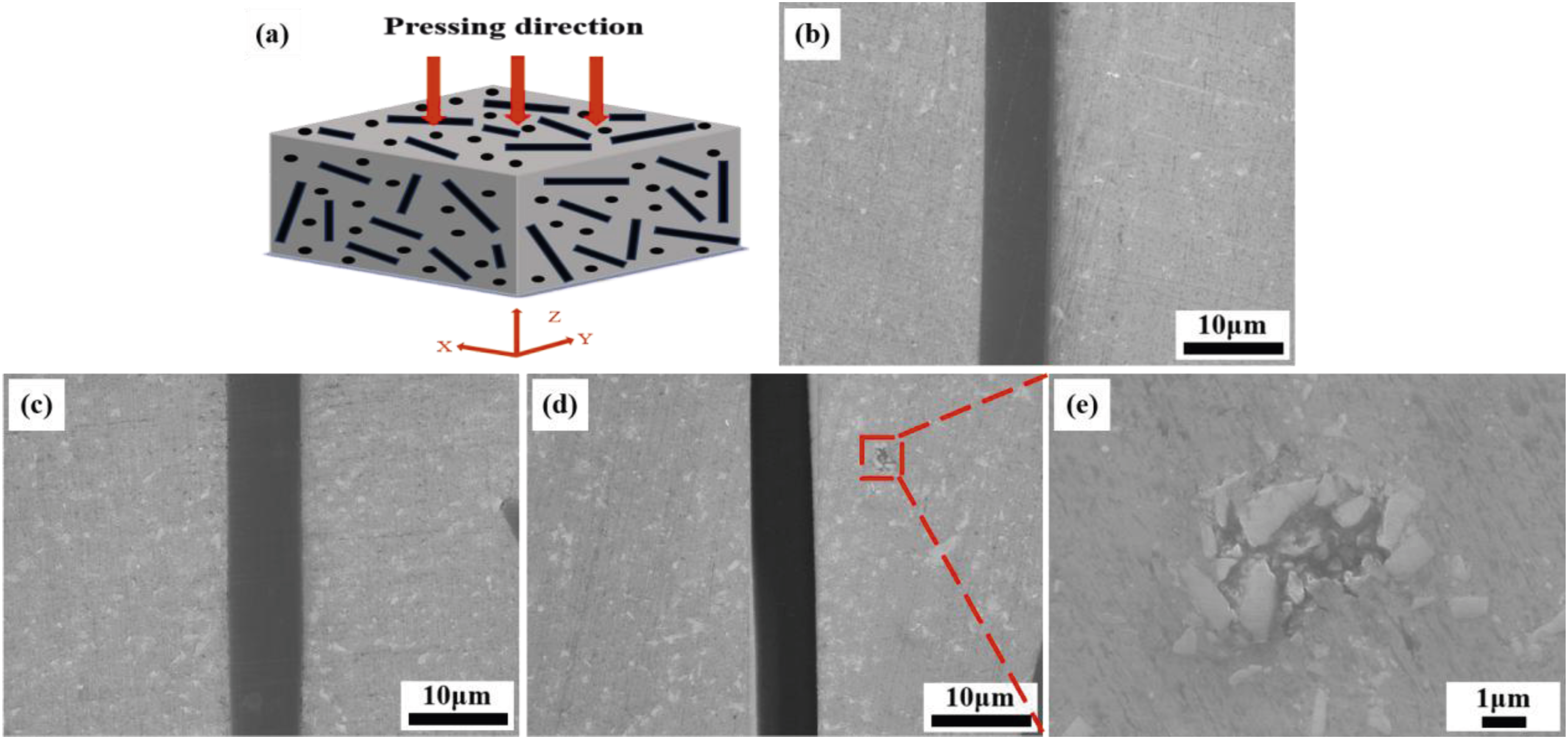
Figure 4 presents the EBSD analysis of SiCp-Cu@CF/Al composites with different SiCp mass fractions. As the SiCp mass fraction increased, the grain size of the composites gradually decreased from 1.9233 μm to 1.5546 μm. This refinement was attributed to the introduction of SiCp, which optimized stress distribution and promoted grain refinement. The SiC nanoparticles, serving as high-melting-point ceramic phases, influenced the grain structure during solidification of the AMCs through heterogeneous nucleation mechanisms. The elevated specific surface area and dispersed distribution of the nanoparticles provided numerous physical nucleation sites for the aluminum melt. The high melting point of SiCp enabled its preferential precipitation during the initial solidification stage, acting as heterogeneous nucleation sites for the aluminum matrix solidification, thereby increasing the nucleation rate. As the SiCp mass fraction increased, the density of nucleation sites further rose, resulting in a more pronounced refinement effect. Additionally, the pinning impact of the particles hindered movement of grain boundaries via the Zener mechanism, according to the Zener formula: IPF maps and grain size distribution maps of SiCp-Cu@CF/Al composites with different SiCp mass fractions: (a-b) 0 wt.%, (c-d) 1 wt.%, (e-f) 3 wt.%, (g-h) 5 wt.%.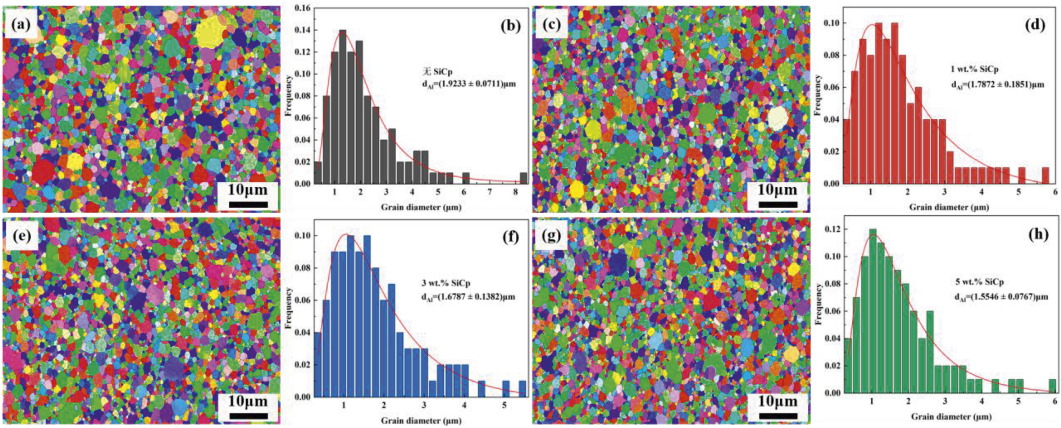
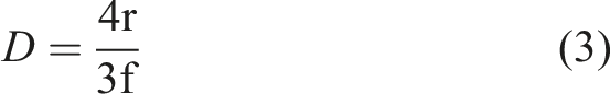
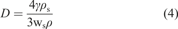
Figure 5 displays the XRD patterns of SiCp-Cu@CF/Al composites with varying SiCp mass fractions. The patterns revealed clearly the characteristic diffraction peaks of the Al matrix and SiC. With increasing SiCp mass fraction, the intensity of the SiC diffraction peaks gradually enhanced, and no significant peak shift was observed. This indicated that within the detection accuracy of the experiment, the SiCp maintained its original crystal structure in the composites, with no significant phase transformation detected. No diffraction peaks corresponding to C were detected in the XRD phase analysis. This was attributed to the low content (1 wt.%) and amorphous nature of the CFs, whose diffraction signal was consequently masked. Furthermore, despite the addition of different mass fractions of SiCp, no diffraction peaks corresponding to Al4C3 were detected in the XRD patterns. This suggests that the interaction between SiCp and the aluminum matrix primarily occurred through physical mechanisms rather than chemical reactions forming new compounds. XRD patterns of SiCp-Cu@CF/Al composites with different SiCp mass fractions.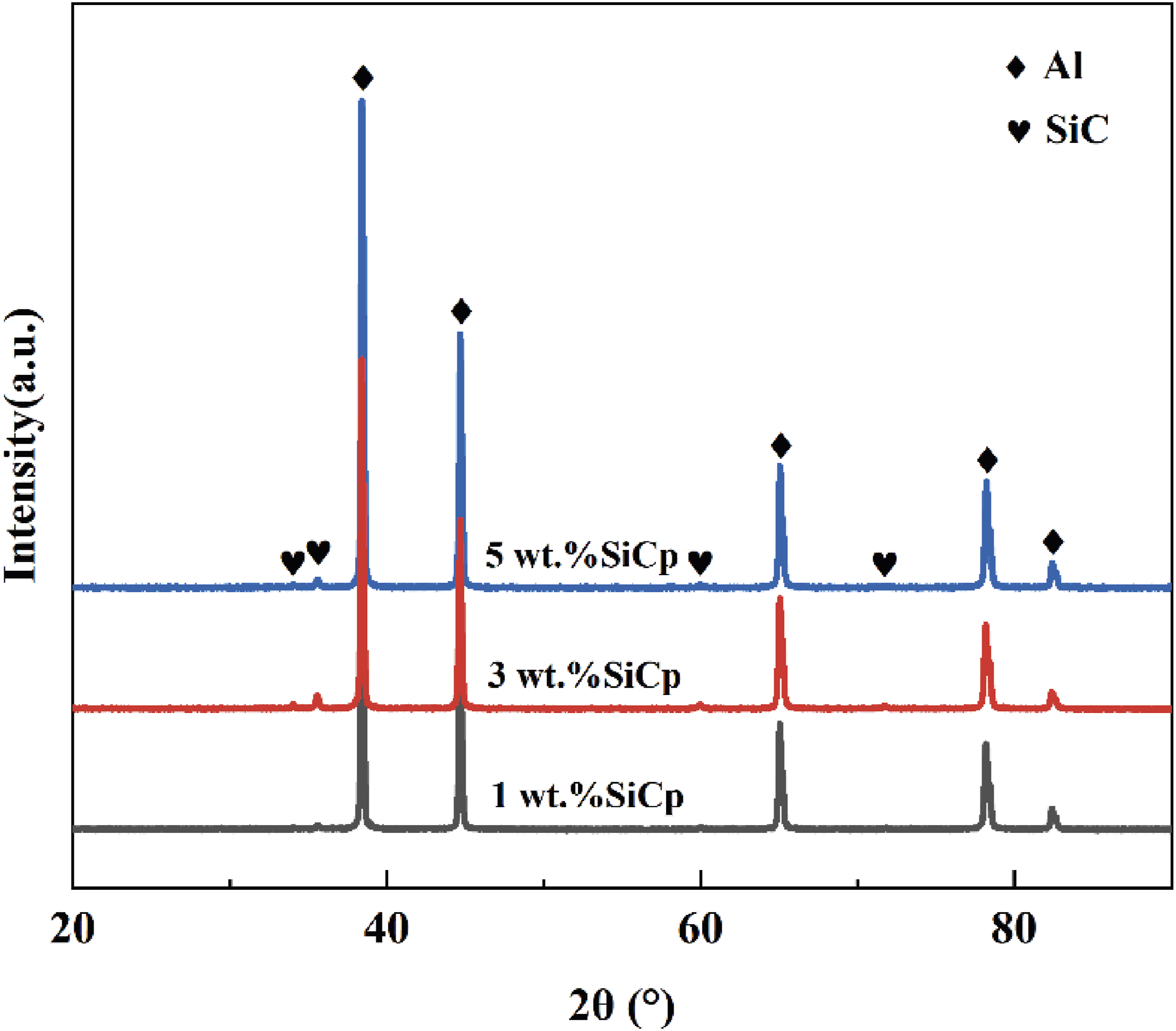
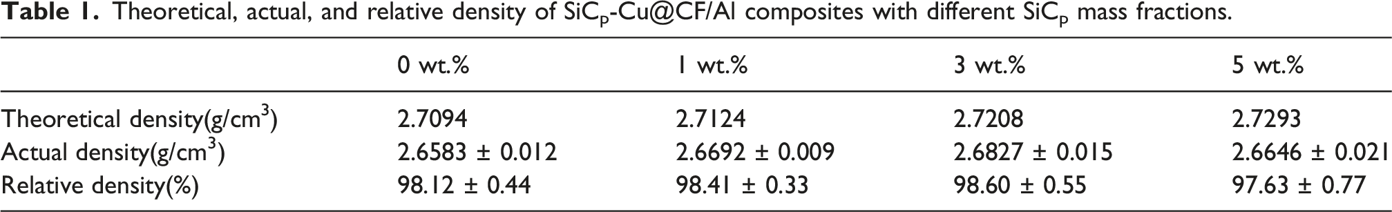
Theoretical, actual, and relative density of SiCp-Cu@CF/Al composites with different SiCp mass fractions.
Mechanical properties of composites
Figure 6(a) exhibits Brinell hardness of SiCp-Cu@CF/Al composites with different SiCp mass fractions. The Brinell hardness of the composites initially rose and subsequently fell with an increasing mass percentage of SiCp. At 3 wt.% SiCp mass fraction, the composite reached its maximum hardness value of 73.47 HB, representing a 30.6% improvement compared to the Cu@CF/Al composite (56.22 HB). This enhancement was attributed to the effective strengthening provided by SiCp through grain refinement and its high intrinsic hardness. However, when the SiCp mass fraction reached 5 wt.%, the hardness decreased due to particle agglomeration at high concentrations, resulting in inhomogeneous distribution. This reduced the effective bonding area between the Al matrix and particles, resulting in poor interfacial adhesion and consequently compromising the composite hardness.
Figure 6 (b)-(c) shows the tensile properties of SiCp-Cu@CF/Al composites with varying SiCp mass fractions. The sudden stress drop after the maximum tensile stress in the engineering stress-strain curves corresponded to unstable crack propagation and final fracture of the composite specimens. The presence of rigid SiC particles and carbon fibers limited plastic deformation after the ultimate tensile strength was reached. With a rise in the SiCp mass percentage, the tensile strength and yield strength of the composites first rose, subsequently declining. The maximum tensile strength of 344.39 MPa was achieved at 3 wt.% SiCp, representing a 22.1% enhancement compared to the Cu@CF/Al composite (281.91 MPa). The enhancement was ascribed to the consistent distribution of SiCp inside the aluminum matrix at this concentration, which synergistically enhanced the strength through dispersion strengthening, grain refinement strengthening, and effective load transfer. Simultaneously, the macro-scale Cu@CF and micro-scale SiCp collectively formed a multi-scale reinforcement architecture: the Cu@CF primarily bore the main load, while the SiCp particles inhibited local plastic deformation of the matrix and collaboratively impeded the initiation and propagation of cracks, thereby significantly improving the fracture toughness and overall strength of the composite. However, when the SiCp mass fraction increased to 5 wt.%, particle agglomeration occurred, resulting in the development of defects and stress concentration in localized regions. The agglomeration not only weakened the interfacial bonding between SiCp and Cu@CF, the aluminum matrix but also disrupted the uniform dispersion of Cu@CF, thereby compromising the continuous load-bearing capacity of the fibers. This resulted in intensified stress concentration at the interfaces and induced premature failure. Additionally, the decline in elongation was primarily due to the rigid constraints imposed by SiCp, which offset the positive effects of grain refinement.
31
(a) Brinell hardness, (b) stress-strain curves and (c) tensile properties variation trend of SiCp-Cu@CF/Al composites with different SiCp mass fractions.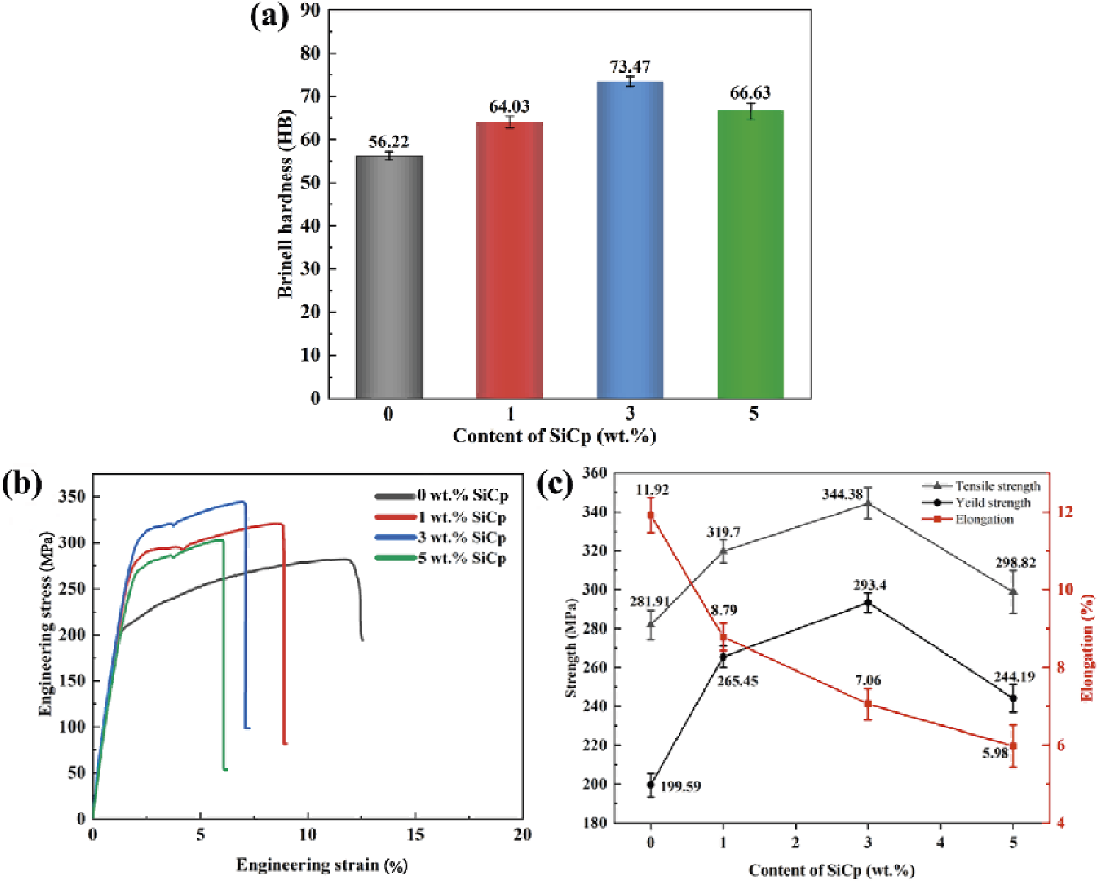
Figure 7 depicts the fracture morphologies and corresponding EDS spectra of SiCp-Cu@CF/Al composites with different SiCp mass fractions. The EDS spectra in Figure 7(c), (f), and (i) detected four elements, C, Al, Si, and Cu in the fracture regions. With increasing SiCp mass fraction, the area proportion of Si gradually expanded. The fracture morphologies in Figure 7(b) and (e) revealed that as the SiCp mass fraction increased, more and finer dimples appeared on the fracture surface, indicating enhanced microscopic deformation capability within the material. This phenomenon was primarily ascribed to the efficient obstruction of dislocation movement by an appropriate amount of SiCp in the aluminum matrix. Furthermore, SiCp refined the matrix microstructure through heterogeneous nucleation and grain boundary pinning. This refinement regulated the nucleation and growth of microvoids during plastic deformation, promoting the formation of numerous fine dimples, which contributed to improved fracture toughness.
32
However, when the SiCp mass fraction increased to 5 wt.%, the fracture surface observed in Figure 7 (h) became relatively smooth with significantly fewer dimples, exhibiting typical brittle fracture characteristics. This was due to particle agglomeration at high reinforcement content, which intensified local stress concentration and weakened the effective interfacial bonding between the matrix and reinforcements. Consequently, the plastic deformation capacity of the composite was markedly reduced, consistent with the sharp decline in elongation shown in Figure 6(c). Fracture morphologies and EDS spectra of SiCp-Cu@CF/Al composites with different SiCp mass fractions: (a-c) 1 wt.%, (d-f) 3 wt.%, (g-i) 5 wt.%.
Figure 8 displays a schematic diagram of the fracture mechanism in the SiCp-Cu@CF/Al composite. Under external loading, microcracks first initiated in the matrix at stress concentration regions, such as pores or interfaces. This typically occurred because areas with relatively lower strength in the matrix were prone to failure under stress concentration. When a propagating crack encountered well-bonded Cu@CF or SiCp, the carbon fibers, due to their high strength and toughness, hindered further crack advancement. The fibers bridging the crack surfaces delayed crack opening and enhanced fracture toughness. Upon encountering SiCp, the crack could deflect, branch, or circumvent the particles, thereby prolonging the propagation path, dissipating more energy, and delaying fracture. When the crack reached regions with weak interfacial bonding between Cu@CF or SiCp and the matrix, interfacial debonding occurred under high stress. For Cu@CF, insufficient interfacial bonding or localized debonding allowed the crack to propagate along the interface, eventually leading to fiber pull-out. Similarly, SiCp experienced debonding from the matrix, facilitating rapid crack propagation along the interface. When the crack simultaneously encountered both Cu@CF and SiCp, multiple resistance mechanisms were activated, including fiber bridging and pull-out from Cu@CF, as well as pinning and deflection from SiCp. In summary, the crack propagation in the composite followed a multi-stage mechanism: “matrix crack initiation — encounter with reinforcements — deflection/pinning/bridging — continued propagation or interfacial debonding — further energy dissipation.” The synergistic interaction between CF bridging/pull-out and SiCp pinning/deflection was identified as the primary reason for the improved fracture toughness.
24
However, insufficient interfacial bonding or excessive reinforcement content could lead to interfacial debonding or defect aggregation, thereby compromising the overall performance of the composite. Schematic illustration for the fracture mechanism of the SiCp-Cu@CF/Al composite.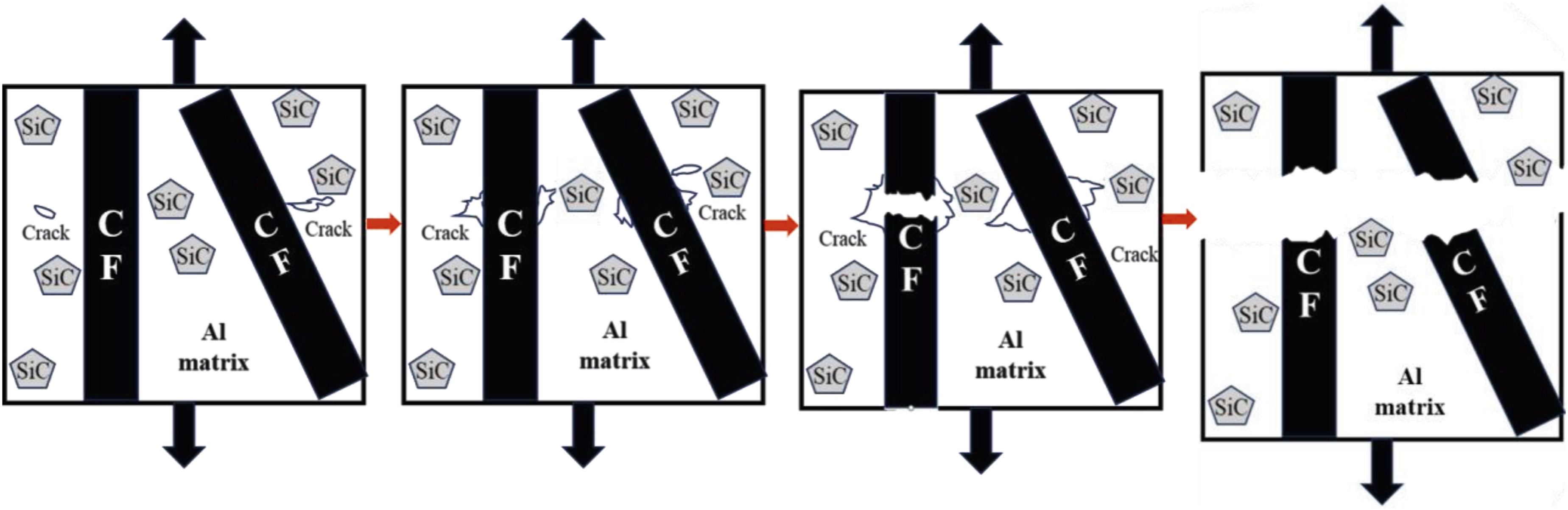
Tribological properties of composites
Figure 9 exhibits the friction coefficient curves of SiCp-Cu@CF/Al composites with different SiCp mass fractions. The friction coefficient of the composites first decreased and then increased with increasing SiCp mass fraction. When the SiCp mass fraction was 3 wt.%, the composite exhibited the lowest average friction coefficient of 0.4526, indicating a 42.7% decrease relative to the Cu@CF/Al composite (0.7912). This reduction was attributed to the increased matrix hardness achieved through grain refinement strengthening and load transfer mechanisms provided by SiCp, which reduced the area of direct interaction between the counterface ball and the aluminum matrix surface during friction. However, when the SiCp mass fraction increased to 5 wt.%, the friction coefficient rose again. This was because excessive SiCp tended to agglomerate in the aluminum matrix, and the uneven distribution of SiCp could form locally rough or sharp microstructures at the friction interface, thereby increasing the overall frictional resistance.
33
Furthermore, significant fluctuations in the friction coefficient were observed during the initial stage, which gradually stabilized as the test progressed. This initial instability occurred because a stable worn layer had not yet formed at the interface during the early friction process, combined with continuous variations in local heat, stress, and micro-contact conditions. As the wear process continued, the Cu@CF gradually played a unique role at the friction interface. Under the combined effects of continuous friction and localized temperature, a fine and uniform lubricating film progressively formed on the surface. This lubricating film not only reduced the friction resistance between the contact surfaces but also provided isolation and buffering effects, effectively suppressing further surface wear and thereby stabilizing the friction coefficient.
34
(a) Friction coefficient curves and (b) average friction coefficient of SiCp-Cu@CF/Al composites with different SiCp mass fractions.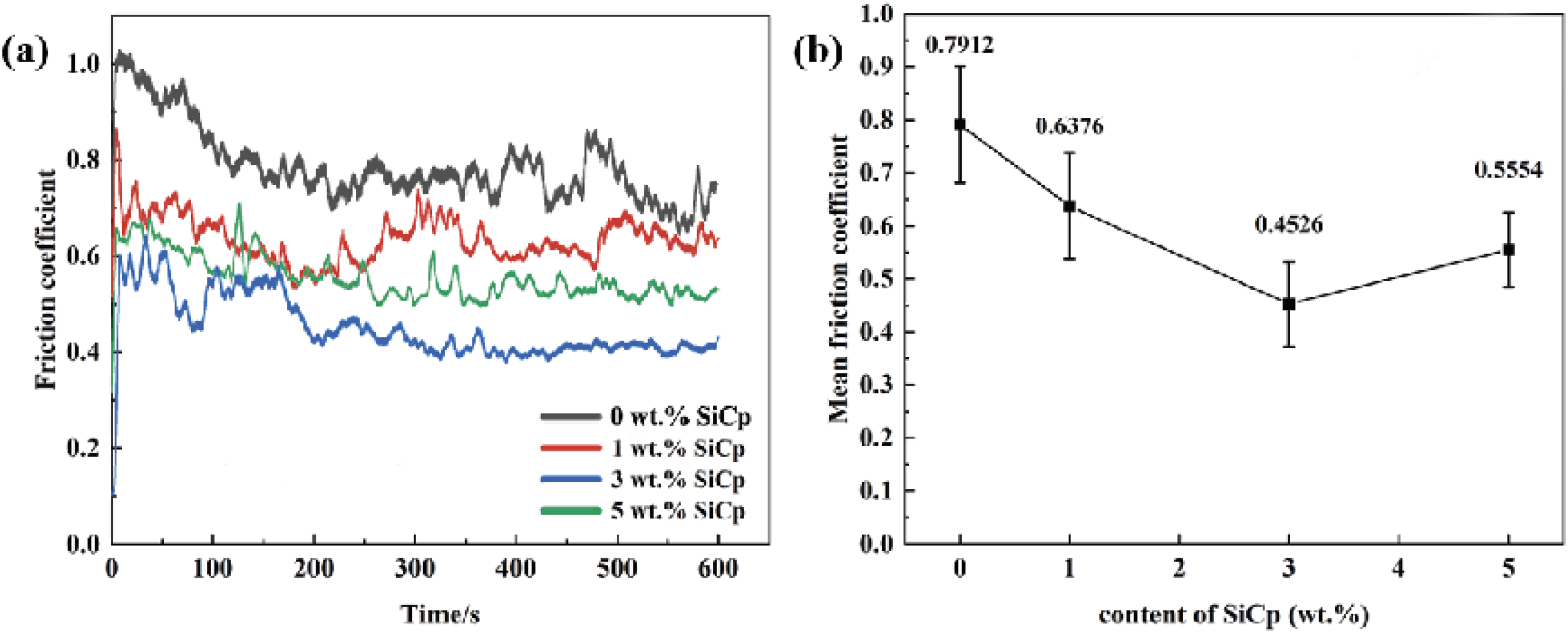
The worn surface morphologies of SiCp-Cu@CF/Al composites with different SiCp mass fractions is shown in Figure 10. As the SiCp mass fraction increased, the wear track width of the composites gradually narrowed, and the amount of wear debris decreased. This indicated that SiCp effectively performed its anti-wear function at the friction interface. On one hand, as high-hardness ceramic particles, SiCp could withstand high contact stress and suppress adhesive wear, promoting the transition of the wear mechanism from adhesive wear to mild abrasive wear, thereby improving the wear resistance of composites.
32
On other hand, Cu@CF not only enhanced the overall strength of the composite but its uniformly dispersed fiber structure also hindered crack propagation, reducing the spalling of localized material during friction. The two types of reinforcements fully utilized their respective advantages, significantly improving the tribological properties of the composite. To further confirm the identification of the fiber-like phase in Figure 10 (d), a high-magnification SEM image and EDS point analysis of the selected region were added as insets. The enlarged image shows a typical elongated fibrous morphology. Meanwhile, the EDS spectrum obtained from the marked region shows a dominant C peak, and no obvious Al, Si, Cu, or O signals are detected. Combined with the morphology and the introduced reinforcement phase, these results confirm that the marked phase in Figure (d) corresponds to carbon fiber. As shown in Figure 10(e), when the SiCp mass fraction was 3 wt.%, the combined reinforcing effect of SiCp and Cu@CF was most pronounced. They formed a relatively uniform stress distribution at the friction interface, alleviating localized stress concentration and significantly improving the wear resistance of the material. Nevertheless, when the SiCp mass fraction further increased to 5 wt.%, as shown in Figure 10(g), although the amount of wear debris further decreased, wear track morphology became irregular, and localized microcracks were observed in Figure 10(h). This was attributed to the agglomeration of high content SiCp, which weakened the continuity of the aluminum matrix and reduced the overall toughness of the material. High stress concentration zones formed in localized areas, making the material more prone to localized spalling wear and microcrack propagation during the friction process.35,36 Worn surface morphologies of SiCp-Cu@CF/Al composites with different SiCp mass fractions: (a, b) 0 wt.%, (c, d) 1 wt.%, (e, f) 3 wt.%, (g, h) 5 wt.%.
Figure 11(a)-(e) displays 3D wear profiles and corresponding cross-sectional profiles of SiCp-Cu@CF/Al composites with different SiCp mass fractions. Both the depth and width of the wear tracks exhibited an initial decrease followed by an increase with increasing SiCp mass fraction, indicating an overall improvement in wear resistance. Figure 11(f) shows the wear rate curves of the composites with different SiCp mass fractions. The wear rate initially decreased and then increased with rising SiCp mass fraction, reaching its minimum value of 0.93 × 10⁻² mm3/N·m at 3 wt.% SiCp, which represented a 66.6% reduction compared to the Cu@CF/Al composite (2.79 × 10⁻² mm3/N·m). SiCp improved the matrix hardness through dispersion strengthening, inhibited plastic deformation via grain refinement, and directly resisted abrasive cutting as hard particles. Meanwhile, the copper coating on CF surface enhanced the bonding between CFs and aluminum matrix, enabling the high strength CFs to effectively bear external loads. Through the synergistic effect between these two components, the composite effectively suppressed abrasive cutting of the matrix and prevented premature fiber pull-out during the wear process, thereby significantly enhancing its wear resistance. The wear mechanisms observed in the present study, including abrasive grooves, adhesive wear traces, fiber pull-out, and interfacial debonding, are consistent with previous reports on CF/Al and SiC–CF/Al hybrid composites. Liu et al.
37
attributed the improved tribological response of SCF/Al composites to the presence of carbon fibers, while Cree et al.
38
reported that the improved wear resistance of A356/SiC foam composites was related to the hardness of SiC and the lubricating effect of carbon. Therefore, the present results further confirm that the combined presence of carbon fibers and Si-rich/SiC regions can improve the wear resistance of Al-based composites by simultaneously providing solid-lubricating and load-bearing effects. Wear 3D profiles and wear rate of SiCp-Cu@CF/Al composites with different SiCp mass fractions: (a) 0 wt.%, (b) 1 wt.%, (c) 3 wt.%, (d) 5 wt.%, (e) cross-sectional profile, (f) wear rate.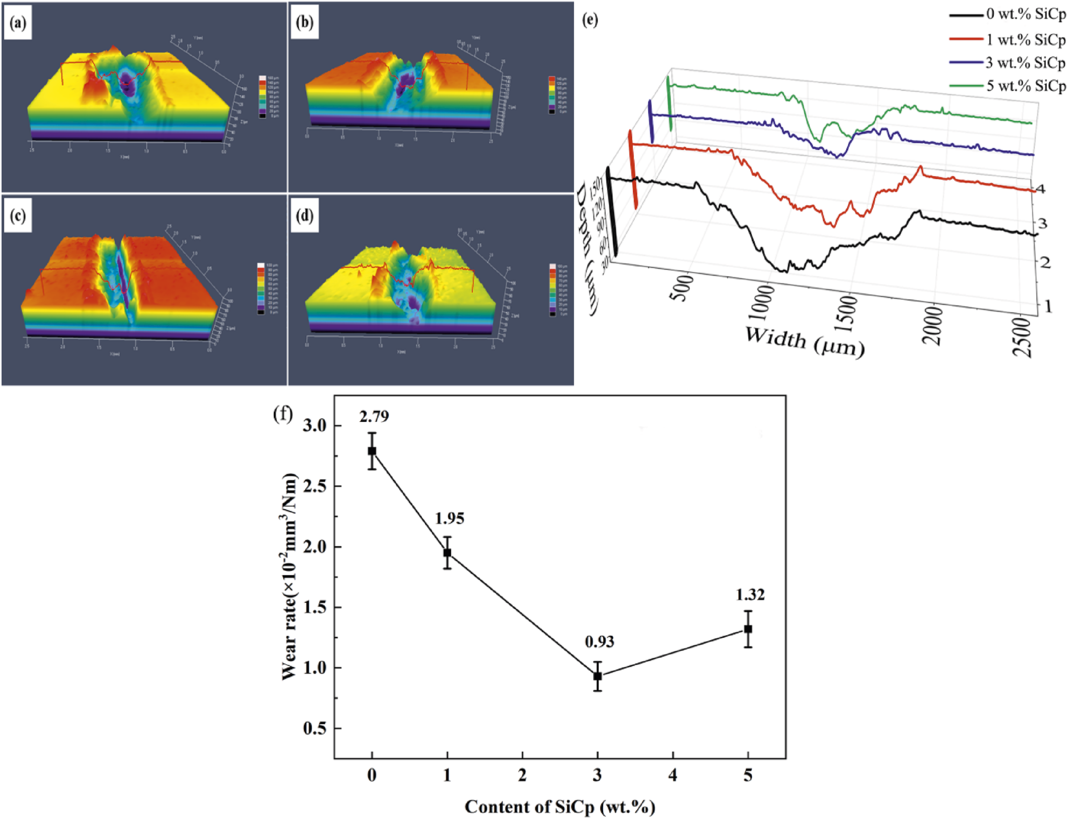
Limitations and future perspectives
Although the present work demonstrates the beneficial effect of hybrid reinforcement by Cu-coated carbon fibers and SiC particles, several limitations remain. First, the carbon fiber content was fixed at 1 wt.%, and only the SiC particle content was varied. Second, the tribological tests were conducted under a single dry sliding condition at room temperature. The effects of load, sliding speed, sliding time, temperature, and lubrication environment were not systematically investigated. Third, long-term wear behavior, fatigue performance, corrosion resistance, and high-temperature stability require further study. In addition, recent studies have shown that multi-criteria decision-making methods, such as the R-method, 39 Entropy-VIKOR, 40 VIKOR, 41 FAHP-TOPSIS, 42 FAHP-FTOPSIS, 43 and AHP-TOPSIS,44,45 can be effectively used to rank and select composite materials based on multiple mechanical, thermal, and tribological criteria. In future work, these MCDM approaches will be introduced to optimize hybrid aluminum matrix composites by considering strength, ductility, hardness, friction coefficient, wear rate, density, processing cost, and service stability simultaneously.
Conclusions
This study, copper-coated carbon fibers and SiC particles hybrid reinforced Al matrix (SiCp-Cu@CF/Al) composites were successfully prepared by powder metallurgy technique. The investigation focused on the microstructure, mechanical properties, tribological properties and the associated strengthening mechanisms of the composites. The principal conclusions are encapsulated as follows: (1) Double reinforcements of SiC particles and carbon fibers were effectively integrated and evenly distributed within the Al matrix using the powder metallurgy method. (2) The hardness and tensile strength of the SiCp-Cu@CF/Al composites first rose and then fell as the mass fraction of SiC particles increased. At 3 wt.% SiC particles, the composite exhibited the optimal hardness of 73.47 HB and tensile strength of 344.38 MPa. (3) The friction coefficient and wear rate of the SiCp–Cu@CF/Al composites initially diminished and subsequently augmented with increasing SiC particles mass fraction. At 3 wt.% SiC particles, the composite exhibited the lowest average friction coefficient of 0.4526 and a wear rate of 0.93 × 10⁻² mm3/N·m. The primary wear mechanism shifts from adhesive wear to abrasive wear. (4) The carbon fibers enhanced the tensile strength through axial load-bearing while simultaneously stabilizing the friction coefficient by leveraging their low-friction characteristics to reduce adhesive effects during sliding. The SiC particles improved the matrix hardness via grain refinement strengthening and load transfer mechanisms, thereby reducing the wear rate. A graded stress distribution formed at their interface, which effectively suppressed crack propagation and significantly enhanced both the mechanical and tribological properties of the composite.
Footnotes
Author contributions
Funding
The authors disclosed receipt of the following financial support for the research, authorship, and/or publication of this article: This work is supported by National Natural Science Foundation of China (Grant No. 52575360) and Jilin Scientific and Technological Development Program (No. 20240402054GH).
Declaration of conflicting interests
The authors declared no potential conflicts of interest with respect to the research, authorship, and/or publication of this article.
Data Availability Statement
Data sharing not applicable to this article as no datasets were generated or analyzed during the current study.