






Abstract
Friction stir processing (FSP)is an effective technique for enhancing material properties by integrating reinforcing particles into a matrix. This study aims to synthesize a novel Mg-Al–Zn surface composite incorporating multiwall carbon nanotube (MWCNT) particles via FSP, and then to evaluate the effects of various processing strategies on particle distribution and material properties, including microstructure, mechanical properties, and tribological performance. Different innovative cavity designs (linear and zig-zag slots) were employed to incorporate MWCNT particles into the base material (BM). In addition, a revolutionary pitch, alternating tool-travel direction between passes, and multiple passes were used as key FSP parameters to induce severe plastic deformation. Results demonstrated uniform particle distribution, significant grain refinement from 33 µm in the BM to 2.65 µm in the linear slot design (LSD) and 4.7 µm in the zig-zag slot design (ZSD), a nearly 100% increase in microhardness, and up to an 82% improvement in tensile strength relative to the BM. Both designs showed improved wear resistance. These enhancements are caused by grain-boundary strengthening and microstructural refinement via continuous dynamic recrystallisation (CDRX). The present study shows that implementing the innovative strategies, such as LSD, achieved enhanced properties of the processed surface composite.
Introduction
Metal matrix composites (MMCs) are designed materials in which a reinforcing phase (metallic, nonmetallic, or ceramic) is embedded in a BM to achieve superior properties.1–3 Among various reinforcing agents used in magnesium-based composites, carbon nanotubes (CNTs) and graphene have become the leading choices as reinforcing materials.4,5 CNTs have a tensile strength of 50 GPa and an elastic modulus of 1000 GPa. These features make it a superior option for reinforcement. 6 Despite these benefits, it remains challenging to achieve homogeneous dispersion of CNTs within the composite matrix. The strong interfacial energy and van der Waals attraction of CNTs contribute to clustering and agglomeration, which together result in an uneven distribution that degrades overall material performance. 7 To address this, researchers have explored various methods of dispersion, such as stir casting with ultrasonic agitation, surfactants, and chemical coating. 6 Unfortunately, these approaches have demonstrated limited success in effectively dispersing CNTs in MMCs. This difficulty necessitates more advanced and effective methods, and FSP, a type of friction stir welding (FSW), offers a promising approach for uniformly dispersing CNTs in the surface composites of magnesium matrices.8,9
FSP is widely recognized as a thermomechanical process for its ability to refine microstructures through severe plastic deformation. Moreover, it’s achieving a uniform particle distribution in the stir zone (SZ).
2
Throughout the FSP, a non-consumable revolving tool with a pin is inserted into the workpiece to generate heat by friction. This softens the material, allowing the tool to penetrate until the shoulder engages the surface. The pin plastically deforms the softened material, inducing immense strain and generating a material flow track that carries the advancing side (AS) material towards the tool’s trailing edge, referred to as the retreating side (RS), as it travels further in the longitudinal direction.
10
Recent advancements have demonstrated the potential of FSP for producing surface composites through the following steps: (1) filling a designed cavity on the substrate with reinforcement particles, as illustrated in Figure 1; (2) Capping pass: The underlying processed layers are sealed using a pin-less tool. (3) Stirring pass: uniformly mix and incorporate reinforcement particles into the matrix using a specially designed stirring tool comprising a pin. The capping pass serves two objectives: first, it prevents the ingress of environmental factors such as oxygen, moisture, and other impurities, which could cause corrosion or wear over time; second, it helps prevent the extraction of reinforcement during the next stirring pass. Stirring passes cause large plastic strain through severe plastic deformation, producing refined grains and a uniform particle distribution. Schematic representation of the FSP operation and slot filling approach of incorporating reinforcement to the BM.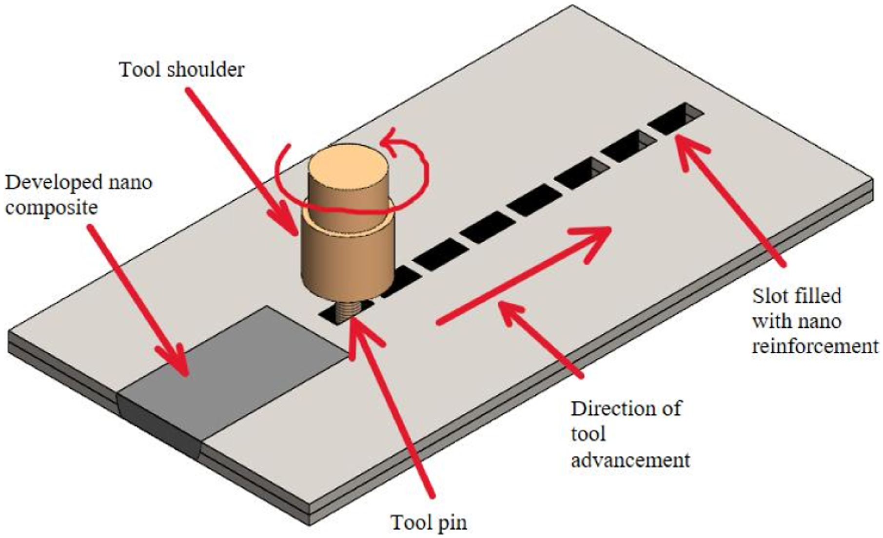
During the FSP process, surface composites are strongly influenced by the working parameters that govern the resulting microstructure and mechanical behaviour. The main parameters, such as rotating speed and travel speed of the tool, the revolutionary pitch (RP) (travel speed/rotating speed), multi-pass, and tool travel direction alternate between passes, and reinforcement addition method, are important in determining the final surface characteristics of the surface composite. Among such parameters, the choice of the cavity in which the reinforcement is to be incorporated is particularly crucial, as it directly influences the uniformity in the particle dispersion.11,12 Different strategies have been established to incorporate secondary-phase particles into the surface, including filling holes or grooves, applying surface coatings,12,13 sandwich arrangements, and direct friction stir processing (DFSP). 14
MWCNTs were first introduced by Morisada et al. 15 into a pre-machined groove in AZ31, and a surface composite was then prepared using the FSP technique. They were able to refine to a fine grain of up to 500 nm. The obtained surface composite was found to have a microhardness 200-300% higher than that of the matrix material. Such improvements were attributed to the various strengthening mechanisms: (1) grain boundaries, (2) strain hardening and (3) precipitation hardening. Soltani et al. 16 incorporated 1% and 2% MWCNT powders in the AZ31 alloy using variable-width grooves that were applied in one or four passes during FSP. A 2% reinforcement weight, achieved through a 3-pass process, provided uniform dispersion of MWCNTs within BM, leading to increased hardness and microstructural homogeneity. Conversely, the 4-pass sample received excessive heat, leading to CNT degradation, whereas the single- and 2-pass samples were only partially mixed. The hole-filling method was employed to incorporate MWCNTs and graphene into the AZ31 Mg matrix, and the resulting 130% increase in microhardness was primarily attributed to grain boundary refinement and the pinning effect. 9 Similar grain reduction and uniform reinforcement distribution were reported during the fabrication of AZ31-based composites reinforced with MWCNTs, GNPs, and TiO2. 17 A novel DFSP technique enabled uniform dispersion of SiC particles in AZ31, resulting in a refined grain size of 1.24 μm from the initial 16.57 μm and an approximately 100% increase in microhardness, primarily due to DRX and a particle-induced grain-boundary pinning mechanism. 14
According to the literature, most previous studies have primarily focused on maximizing the properties of fabricated composites by varying the matrix material, reinforcement type, reinforcement size, and reinforcement volume fraction. In addition, conventional groove- or hole-filling techniques along with different FSP processing parameters have generally been employed in the fabrication of surface composites.
However, relatively little attention has been paid to developing effective reinforcement-adding strategies that achieve uniform reinforcement distribution, controlled material flow, and defect-free composite formation. 12
In this context, the present work is significant because it emphasises the relationships among processing, microstructure, and properties through the implementation of novel LSD- and ZSD-based approaches. The zigzag groove pattern used in the LSD and ZSD approaches creates alternating material flow paths during tool rotation and traversal, which increase multidirectional stirring. This turbulent flow enhances the breakup and uniform dispersion of reinforcement particles throughout the SZ, resulting in a more homogeneous microstructure.18,19 In addition to forming different cavities to incorporate reinforcement, strategies such as changing the rotation direction between passes have been observed to promote a more uniform distribution of reinforcement particles within the SZ. 20 The changing-direction pass (CDP), in which the stirring direction alternates after each pass, combined with alternating between AS and RS, substantially softens the matrix and achieves a homogeneous distribution of the reinforcements.
The present study focuses on implementing novel strategies, such as LSD and ZSD, for the fabrication of AZ31/MWCNTs-based surface composites. The study investigates the microstructural, mechanical, and tribological properties of the fabricated surface composites, while also providing deeper insight into defect evolution and material flow behavior during FSP. Therefore, the novelty of the present study lies not merely in achieving higher property values, but also in establishing an effective fabrication strategy for producing more uniform, defect-controlled, and structurally reliable surface composites.
Materials & methods
Materials
Properties of AZ31 material.

Methods
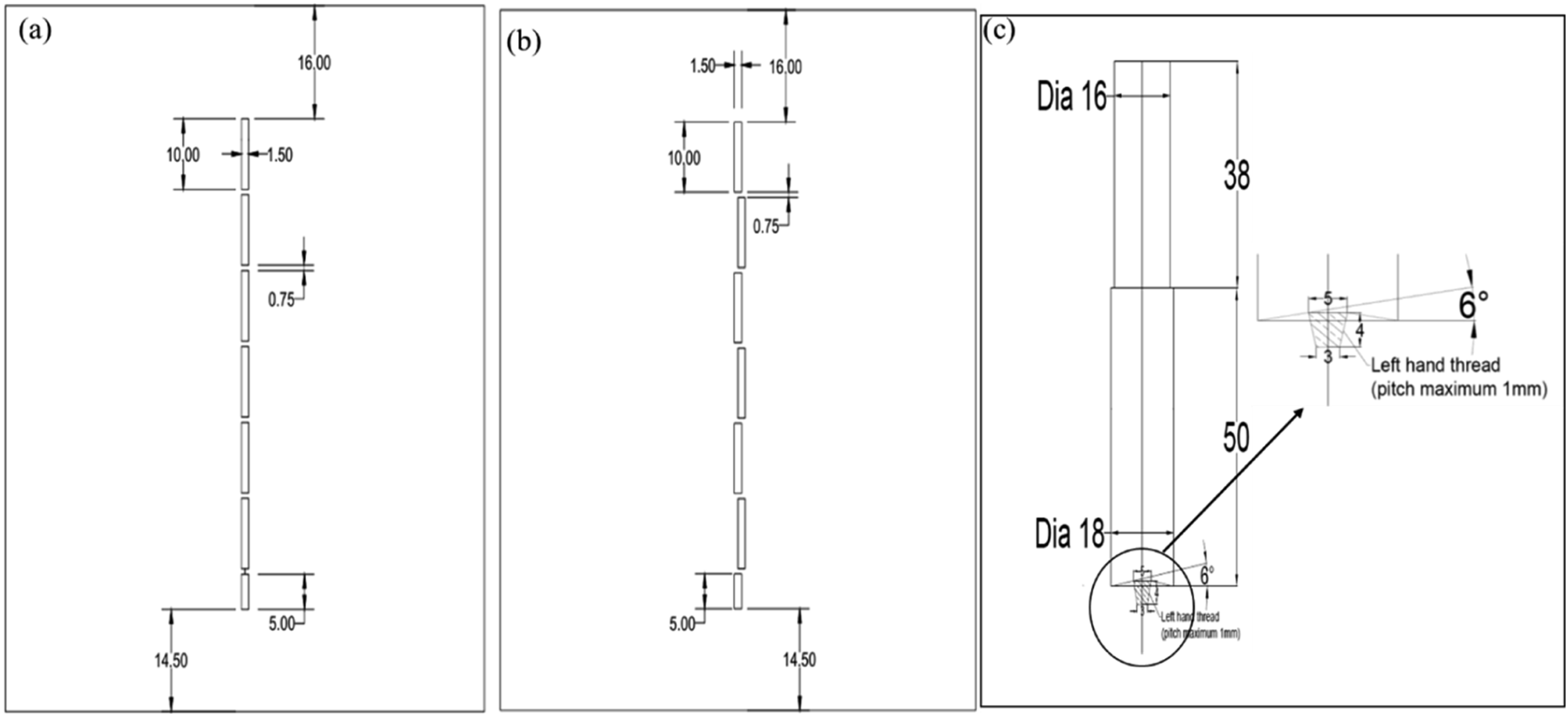
A vertical milling machine was employed to prepare linear and zigzag cavities on the AZ31 Mg substrate, as shown in Figure 2(a) and (b). The cavities were filled with MWCNT particles, maintaining a constant volume fraction of 18.5%. The cavities were designed to accommodate this specified fraction using equations Design of novel strategies for adding reinforcement (a) LSD, (b) ZSD and (c) configuration of H13 tool, featuring a conical threaded pin with a concave shoulder.


Processing parameters for the FSP.

Specimens were cut using electrical discharge machining (EDM) to investigate microstructural, mechanical, and tribological properties, as shown in Figure 3. To examine the microstructure, the surface composite specimen was polished and then etched using an acetic acid-picric acid etchant containing 70 ml ethanol, 10 ml distilled water, 10 ml acetic acid, and 4.2 g picric acid.
21
Optical microscopy (OM) and field-emission scanning electron microscopy (FE-SEM) were used to investigate the microstructure. Grain morphology analysis using electron backscatter diffraction (EBSD)was subsequently performed. In addition, energy-dispersive X-ray spectrometry (EDS) was carried out for the elemental distribution in the SZ. Microhardness was measured using a Vickers hardness tester with a 100g load and a 10s dwell period. Microhardness was measured using a Vickers hardness tester with a 100g load and a 10s dwell period. Indentations at 0.5 mm intervals, running parallel to and 1 mm below the surface of the top, were made over the area being processed.
22
To measure the mechanical response, three samples of each composite were tested using a Universal Testing Machine (UTS) in accordance with ASTM E8, at a crosshead travel speed of 0.5 mm/min.
23
The wear behaviour of the processed surface composites was investigated by running pin-on-disk wear tests on a wear-testing machine (DUCOM). A cylindrical pin (6 × 6 mm 2) was required to contact an EN31 hardened steel disk (65 HRC) as the counter surface in each test. The experiment was conducted under controlled conditions, including a load of 20 N, a wear-track diameter of 80 mm, a sliding distance of 500 m, and a sliding speed of 1 m/s, which ensured consistent and reliable wear behaviour. Different specimens extracted from the processed composite for characterization.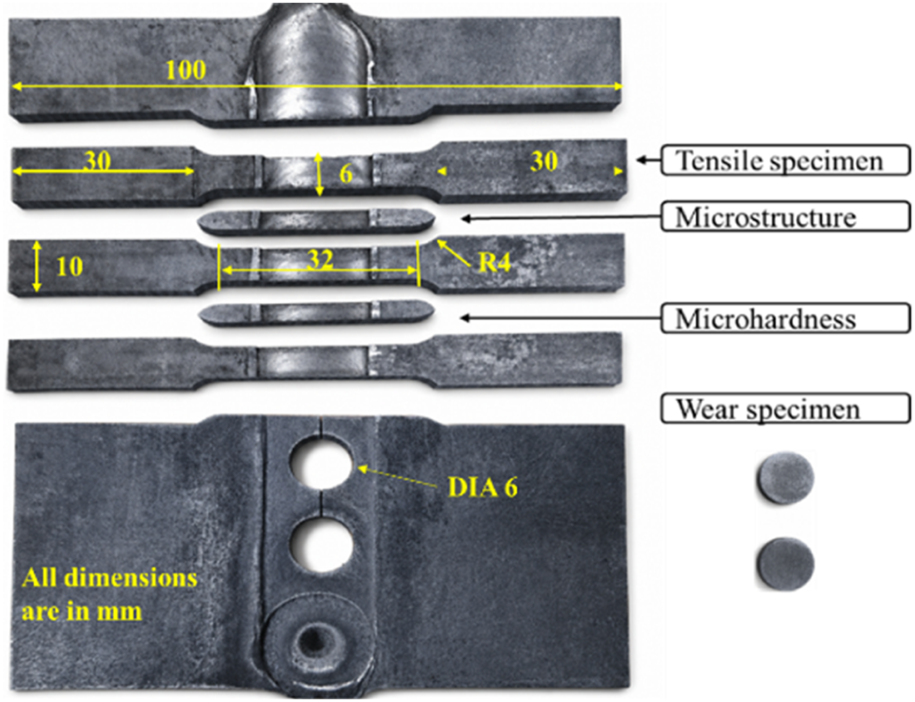
Results & discussion
Microstructural behaviour
Producing defect-free surface composites through FSP is not straightforward; it requires a careful balance of parameters such as tool travel speed, rotation speed, tilt angle, number of passes, and the strategy used for incorporating reinforcement particles. As shown in Figures 4 and 5 The optical macrographs of the MWCNT/AZ31 composites revealed onion-ring formation in the SZ. They also clearly delineated zones such as the SZ, thermo-mechanically affected zone (TMAZ), and heat-affected zone (HAZ) formed during processing. Macro and micrograph showing material flow pattern in different zones with 0.1RP for (a) LSD samples, (b) ZSD samples. Macro and micrograph showing material flow patterns in different zones with 0.05 RP for (a) LSD samples, (b) ZSD samples.

Figure 6(a) schematically illustrates the powder distribution mechanism during FSP, where the tool’s plunging action drives particles upward toward the shoulder, and subsequent rotation imparts forces that disperse them outward into the SZ. Meanwhile, some particles become entrapped between the tool pin and the BM, where they are fragmented, refined, and uniformly embedded (Figure 6(b)), forming alternating layers in the SZ that consolidate into the SZ, as shown in Figures 4 and 5. Changing the stirring direction in successive passes helps to equalize the material flow on both sides of the tool, ensuring uniform particle movement across the SZ. Moreover, increasing the number of FSP passes results in a further reduction in the grain size within the SZ, primarily because each additional pass enhances the dispersion of nanosized particles and triggers renewed recrystallization, thereby leading to additional microstructural refinement.
24
Schematic illustration of reinforcement particle distribution (a) during the FSP process and (b) after the FSP process.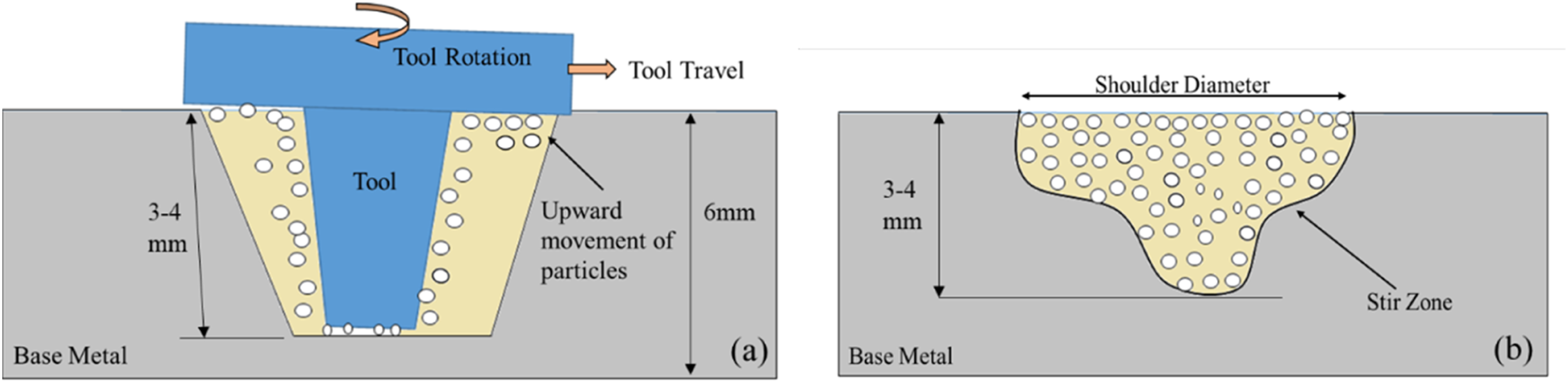
Building on this understanding of material flow and distribution, the effect of RP on the behaviour of LSD- and ZSD-based surface composites becomes more apparent. At a higher RP of 0.1, the micrographs of the different zones in Figure 4 clearly reveal the material movement with an onion ring in the SZ of both the LSD- and ZSD-based surface composites. This behaviour can be attributed to appropriate heat generation and strain rate, as governed by the Zener–Hollomon parameter (Z), which is influenced by higher RP. The above processing conditions promote dynamic recrystallisation, leading to the formation of small equiaxed grains in the SZ and supporting the observations of the SZ reported by Morisada et al.
25
The SZ temperature distribution also supports this observation. Equation (4) can be used to estimate the maximum temperature (Tmax).
26

Homogeneous distributions with defect-free SZ with an onion-ring structure are displayed in Figure 5(a) and (b) for the LSD- and ZSD-based composites processed with 0.05RP during the cumulative pass. This resulted from the downward flow of the material combined with the helical upward movement induced by the conical-threaded tool at an RP of 0.05. With this lower RP, the reduced tool travel rate increases the contact time between the tool and the workpiece, resulting in prolonged thermal exposure of the material. This extended interaction increases friction at the tool–workpiece interface, thereby producing a maximum temperature of around 380°C during the process. Consequently, these temperatures are sufficient to soften the magnesium alloy in the SZ, which typically ranges from 350 to 450°C, thereby promoting optimal softening and stable material flow during FSP.28,29 Meanwhile, grain refinement is achieved through two mechanisms: (1) increasing the number of passes leads to higher accumulated strain, which promotes a more uniform and finer-grained microstructure; and (2) Zener pinning by the reinforcement, which becomes more effective with increasing nanoparticle content and decreasing particle diameter. Consequently, the fine CNTs exert a strong pinning force on grain boundaries, thereby enhancing grain refinement.
21
Owing to the above reason, fine-grained structure in the SZ of the LSD- and ZSD-based surface composites, as shown in Figure 7(a) and (c). This uniformity was further evidenced by the continuous flow lines that developed into an onion-ring pattern within the SZ, as illustrated in Figure 7(c). The upper SZ exhibited minor clustered reinforcement particles in the ZSD-based composite, indicating upward migration and entrapment in the stagnant zone. In contrast, the lower SZ exhibited uniform dispersion without agglomeration. Asadi et al.
30
observed that even at a lower RP, alumina nanoparticles were uniformly distributed in Al2O3/AZ31 surface composites, a trend consistent with the observations of Morisada et al.
25
and Vahedi et al.
31
Microstructure illustrating reinforcement dispersion in SZ of LSD based samples(a) 0.05RP, (b) 0.1RP and ZSD-based samples (c) 0.05RP, (d) 0.1RP.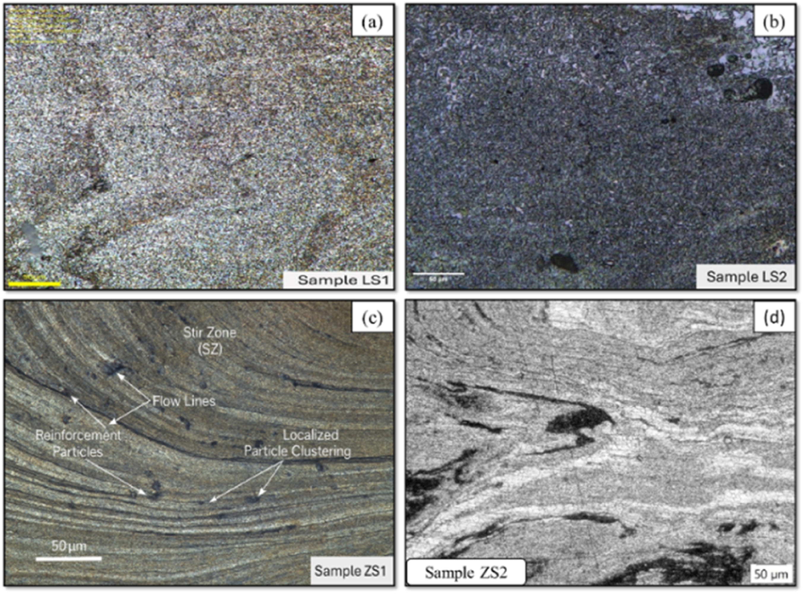
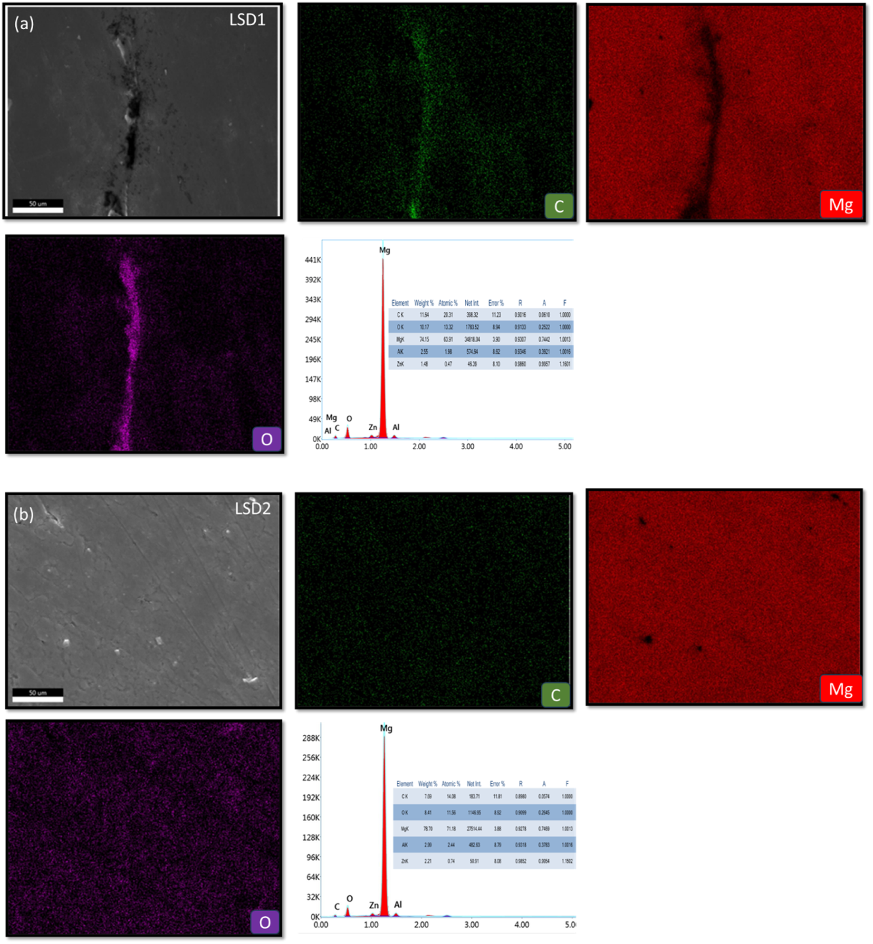
The FE-SEM micrographs in Figure 8(a) and (b) reveal the homogeneous distribution of MWCNT within the BM in the SZ of the LSD-based processed composites, where the yellow arrows highlight the presence and dispersion of MWCNTs throughout the matrix. Building on these observations, the EDS mapping shown in Figure 9(a) and (b) further confirms that the MWCNTs are uniformly dispersed throughout the metal matrix in the SZ of both the LSD-based surface composites. Singh et al.
17
and Sharma et al.
9
highlighted the consistent behaviour of MWCNTs in AZ31 under severe plastic deformation conditions, which supports the uniform distribution observed in this study. SEM image showing particle distribution in SZ of LSD-based surface composite (a) 0.05RP, (b) 0.1RP. EDS elemental mapping results from the SZ of the LSD samples processed at (a) 0.05 RP and (b) 0.1 RP.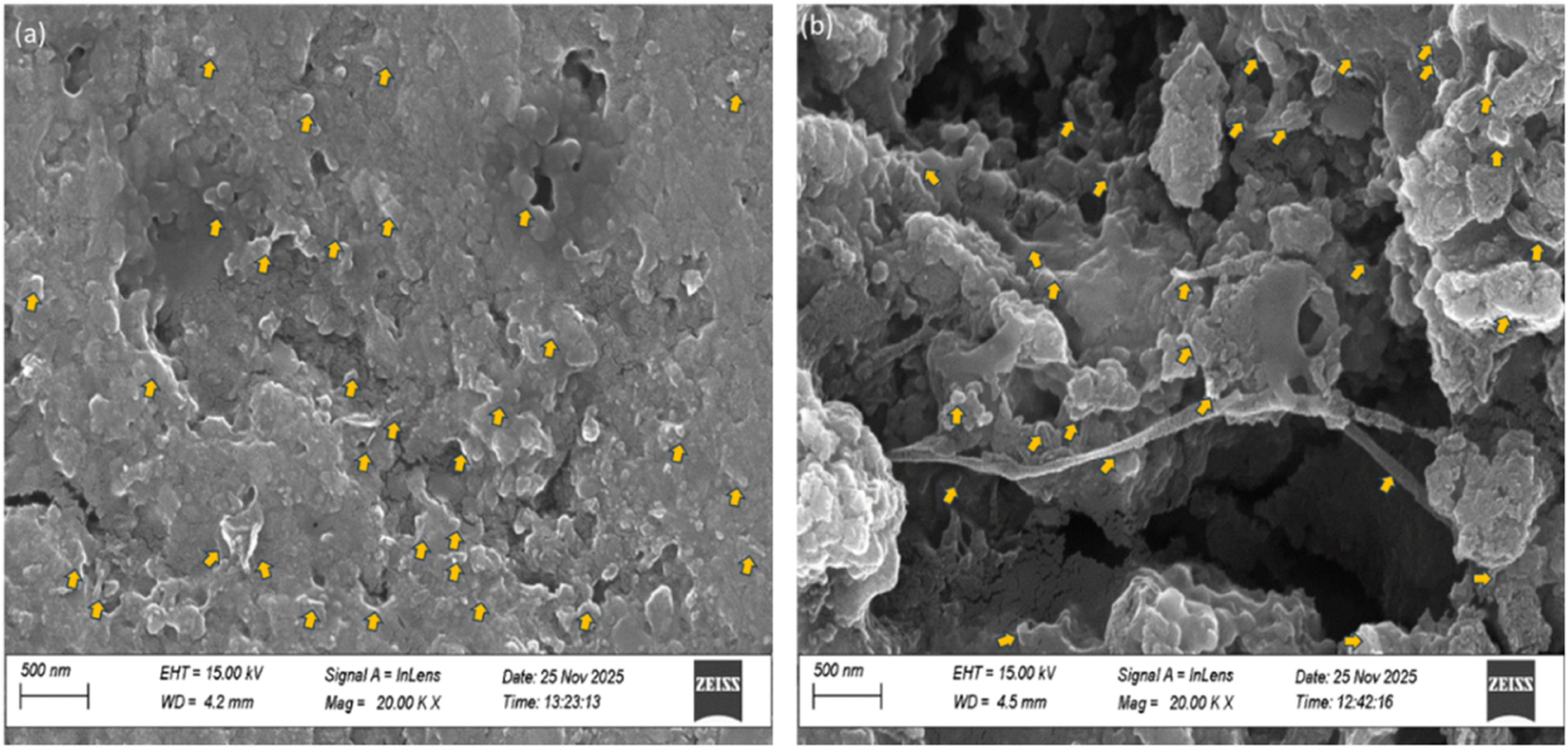
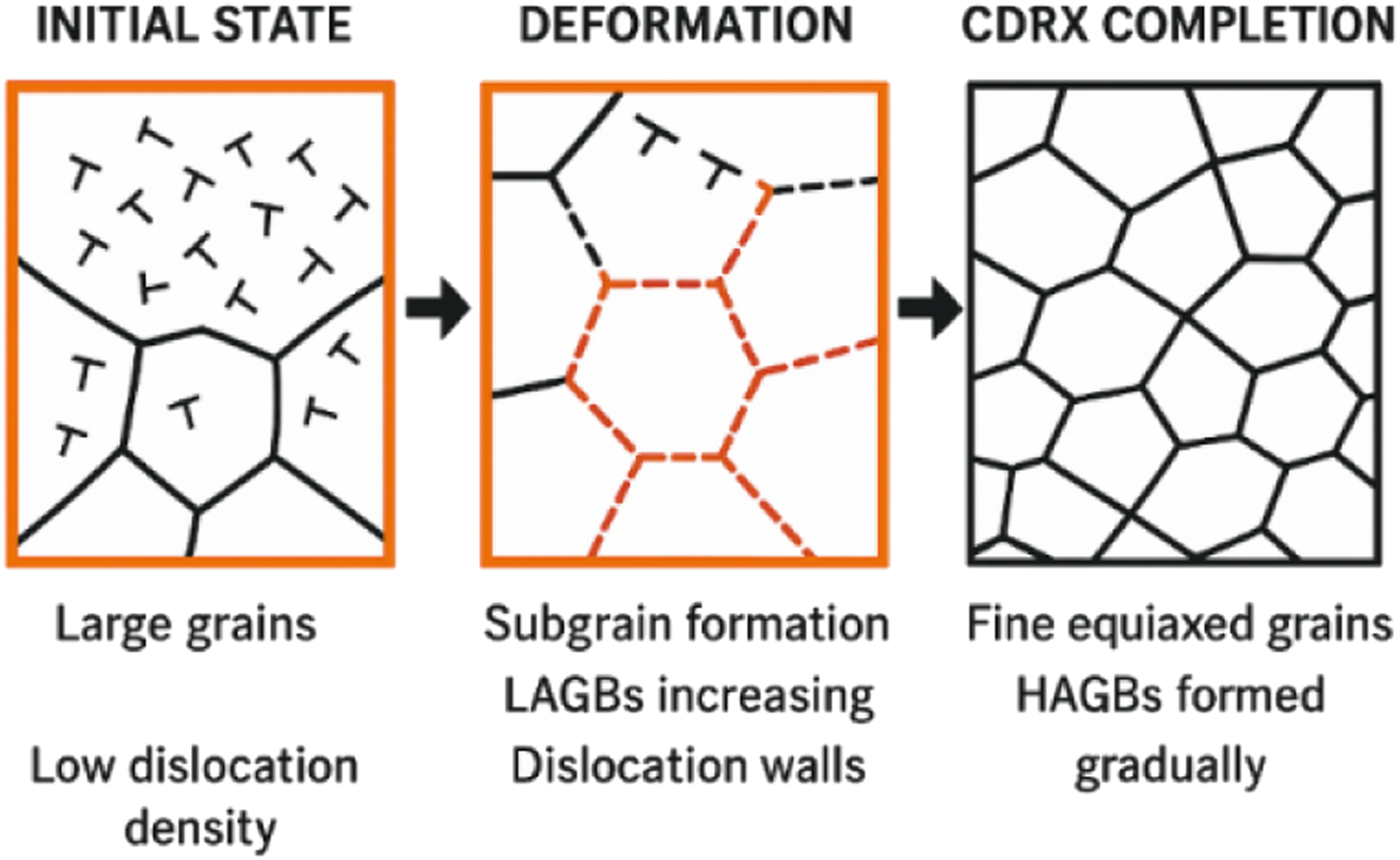
Furthermore, during severe plastic deformation processes, such as FSP, the substrate material initially consisted of large grains with a low dislocation density. As deformation progresses, high strain drives dislocations toward grain boundaries, eventually forming subgrains, which in turn increase the volume fraction of low-angle grain boundaries (LAGBs). With increasing strain, these LAGBs progressively transform into high-angle grain boundaries (HAGBs), as shown in Figure 10, indicating the progression of continuous dynamic recrystallization (CDRX).
26
Ultimately, this results in a refined microstructure characterized by fine equiaxed grains. In Mg, dislocations predominantly move along a single slip plane and tend to accumulate near HAGBs. This is because Mg alloys have a hexagonal close-packed (HCP) structure with only three slip systems, of which only two are independent and do not satisfy the Von Mises criterion, which requires five independent slip systems for uniform plastic deformation.32,33 Schematic illustration of the formation process of LAGBs and HAGBs during CDRX
34
.
This accumulation causes lattice rotation owing to the high dislocation density in these regions, leading to grain fragmentation and the formation of multiple LAGBs, which serve as favourable sites for the nucleation of recrystallized grains through the CDRX mechanism. 31 Additionally, fine MWCNTs strongly restrict grain-boundary migration via the Zener pinning mechanism, thereby enhancing grain refinement.17,21
As a result of this mechanism, the surface composites produced using LSD exhibited variations in grain size across the SZ, TMAZ, and HAZ, as shown in the EBSD map in Figure 10. In the SZ, severe plastic deformation and CDRX resulted in highly refined, equiaxed grains with an average grain size of ∼3-8 µm in 0.05RP (Figure 11(a)) and 2-6 µm in 0.1RP (Figure 11(b)), indicating significant grain refinement compared to the BM (∼33 µm). The TMAZ exhibited elongated, deformed grains with partial recrystallization resulting from the combined effects of the thermal and mechanical stresses. The average grain size in this region was slightly larger, ranging from approximately 8 to 17 µm. In contrast, the HAZ, which undergoes only the thermal cycle without substantial plastic deformation, promotes grain growth, resulting in coarser grains. Similarly, the ZSD yields grain sizes of approximately 4-8 µm in SZ, indicating a reduction of up to 86% compared to the as-received BM, which initially contained large grains (∼33 µm), as shown in Table 3. The shift from coarsened grains in the HAZ to elongated grains in the TMAZ and fine equiaxed grains in the SZ highlights the combined effects of deformation, CDRX, strain rate, and frictional heat, which agrees with the findings of Khodabakhshi et al.
35
IPF maps showing grain morphologies in different zones of LSD-based surface composites (a) with 0.05 RP, (b) with 0.1 RP. Properties of the fabricated surface composite.

During processing, the SZ experiences high-temperature deformation owing to its high stacking fault energy (SFE). This promotes dislocation generation, annihilation, and the formation of subgrains within the existing grains, as shown in Figure 10. Owing to this deformation, Figure 12 shows a clear shift in the misorientation angles from LAGBs to HAGBs as the region transitions from HAZ to SZ for the LSD-based surface. This confirms the occurrence of CDRX and significant grain refinement in the fabricated surface composite. This trend was observed by Ali et al.
36
and Li et al.
37
Misorientation angle distribution histograms for the different zones of the LSD-based surface composite processed at 0.05 RP.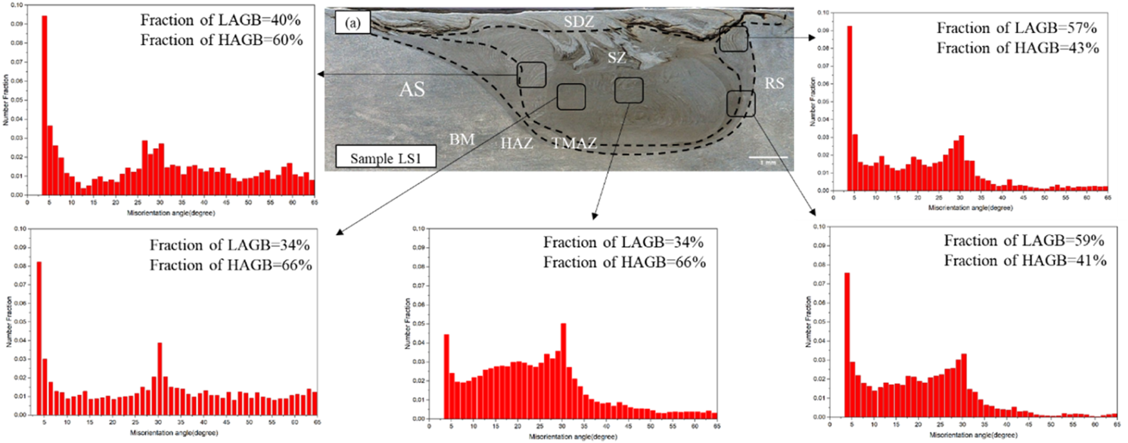
Furthermore, when nanoparticles were introduced as reinforcements, they promoted the transformation of a greater proportion of LAGBs into HAGBs. Thus, it enhances the evolution of the material’s boundaries. Similar observations were reported by Jain et al. 38 and Ali et al. 36 The incorporation of MWCNTs via FSP increased the mean misorientation angle from 19.50% in the base material to 20.35%, 20.87%, and 21.99% in the HAZ, TMAZ, and SZ, respectively. The same result was observed by Khodabakhshi et al. 35
Defects
Various defects, such as tunnelling, wormholes, and agglomeration, were observed in the fabricated specimens. Tunnelling defects were observed in the ZSD-based surface composite with 0.05 RP, as shown in Figure 5(b). These defects were primarily caused by insufficient forging action due to inadequate plunge depth and improper processing conditions, thereby increasing material flow resistance and restricting plastic deformation. As a result, the stirred material failed to completely refill the cavity formed behind the advancing tool, leading to the formation of internal tunnel defects. 39 Furthermore, the high flow stress of the base material and the presence of reinforcement particles further hindered smooth material flow and consolidation during processing. Such defects act as stress concentration sites, thereby reducing the effective load-bearing cross-sectional area and deteriorating the mechanical properties of the fabricated surface composites. Similarly, wormholes, which are internal cavities, form due to incomplete material convergence and are often exacerbated by particle incorporation, high flow stress, and reduced stirring momentum at an RP of 0.05, as shown in Figure 5(b).
In the sample with 0.1RP, severe agglomeration of MWCNTs was observed on the AS side, particularly in the LSD sample. Defects were observed in the lower region near the SZ–TMAZ interface, as shown in Figure 4(a). In contrast, a more pronounced agglomeration was observed in the TMAZ of the ZSD-based composites with 0.1RP, as illustrated in Figure 4(b). This behaviour is aggravated by the inherently entangled structure of the MWCNTs, which, under reduced turbulence, tend to align and form clusters through entanglement and van der Waals interactions. At the same time, inadequate plasticization prevents the material from attaining the viscosity required for effective dispersion of MWCNTs in the BM, 19 ultimately leading to agglomeration of the reinforcement. This result was consistent with the findings of Morisada et al. 35
Mechanical properties
The microhardness of the processed samples was evaluated at a depth of 1 mm below the plate’s top surface. The hardness distributions of the samples produced using different processing parameters are shown in Figure 13(a). The LSD-based composites exhibited higher average microhardness values of 97.4 HV and 100 HV for 0.05 RP and 0.1 RP, respectively, corresponding to a 95–100% improvement over the BM (50 HV). However, the ZSD–based composites showed comparatively lower values of 86.97 HV and 81.66 HV at 0.05 RP and 0.1 RP, respectively, than the LSD samples, but still representing a 64–74% increase over the BM. Consequently, the LSD samples exhibited superior hardness because this strategy retained a greater volume of reinforcement particles and achieved a more uniform dispersion than the ZSD samples. A comparison of microhardness across different zones of the processed samples revealed that hardness was highest in the SZ and gradually decreased toward the HAZ (Figure 13(a)). (a) Microhardness distribution of processed surface composites and (b) LSD sample with 0.1RP, (c) ZSD sample with 0.05RP shows localised hardness.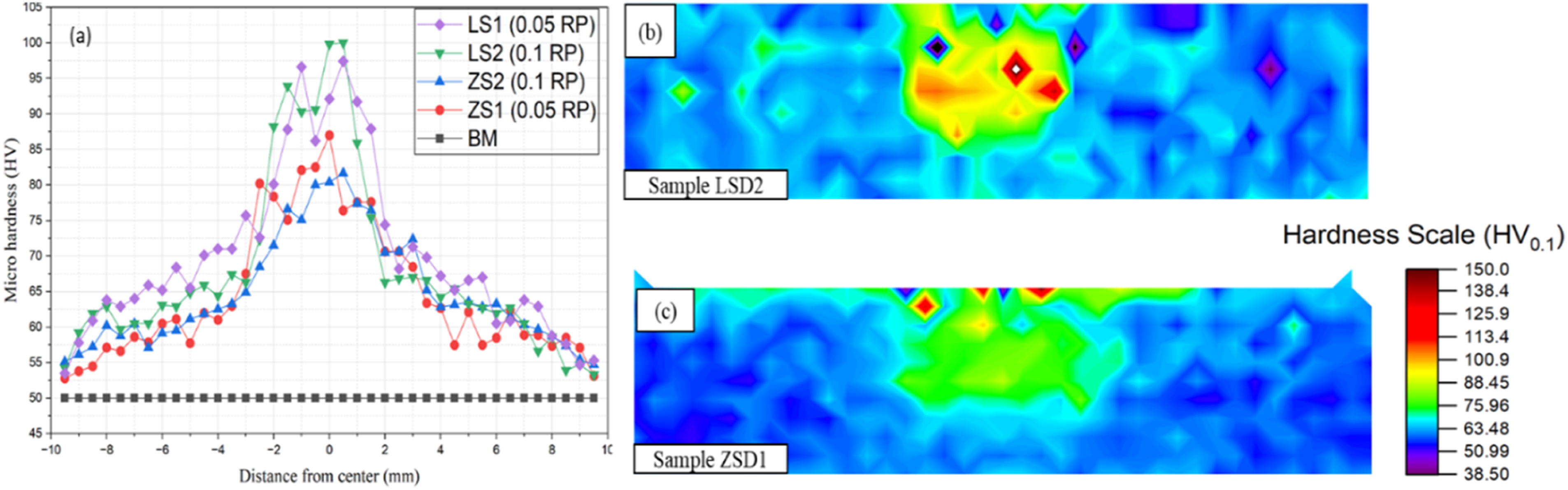
The increase in hardness within the SZ can be attributed to multiple strengthening mechanisms, as calculated using equation (5). (1) Grain refinement (HG): The generation of ultrafine grains in the nanocomposite matrix resulted from DRX occurring within the SZ during FSP. Such refined grains act as effective barriers to dislocation motion, thereby significantly enhancing the nanocomposite’s hardness. The strengthening contribution associated with grain refinement can be explained by the Hall–Petch relationship as shown in equation (6). (2) Orowan Strengthening (HO): According to the Orowan strengthening mechanism, the uniformly dispersed MWCNTs in the SZ act as obstacles to dislocation motion (pinning effect), thereby restricting plastic deformation during indentation. Since dislocations cannot cut through the rigid nanotubes, they bypass them by forming Orowan loops, thereby enhancing the composite’s hardness. 9 (3) Dislocation strengthening (HCTE): The significant difference in the coefficient of thermal expansion (CTE) between the AZ31 matrix and MWCNT reinforcement generates thermal mismatch stresses during cooling after FSP, owing to the higher thermal contraction of magnesium compared to MWCNTs. This mismatch induces a high density of dislocations near the matrix–reinforcement interface, while the dispersed MWCNTs hinder dislocation annihilation and recovery by acting as effective barriers to dislocation motion. Consequently, the retained dislocation density increases work hardening and contributes to improved hardness. 40
Thus, the hardness of the AZ31/MWCNTs surface composite (Hcom), which had the maximum average hardness, can be calculated using the equations below
41
:
In equation (5), HBM represents the hardness of the BM. The Hall–Petch relationship was used to estimate HG, which corresponds to the hardness contribution arising from grain refinement in the reinforced matrix after three-pass FSP. For the AZ31 Mg alloy, the Hall–Petch equation is expressed as follows
42
:
Where d is the mean grain size. Based on the microstructural examination, the average grain sizes of the as-received material and the LSD1, LSD2, ZSD1, and ZSD2 samples after three FSP passes were found to be 33, 3.66, 2.65, 4.7, and 5.5 μm, respectively. According to equation (6), the calculated microhardness values were 52, 78, 84, 73, and 71 HV. The noticeable difference between the experimental and calculated hardness values arises because the equation considers only the grain-boundary-strengthening effect and neglects the contribution of reinforcement particles. This indicates that the calculated values primarily reflect the hardness contribution from grain-refinement strengthening (HG), whereas the experimental values are additionally influenced by Orowan strengthening (HO) and by the increased dislocation density generated by the CTE mismatch between the matrix and the reinforcement (HCTE). Therefore, the improvement in the hardness of the AZ31/MWCNTs nanocomposite can primarily be attributed to the grain-refinement strengthening mechanism. The hardness in the HAZ decreased due to grain growth and grain coarsening during slower cooling. In contrast, the TMAZ exhibited higher hardness due to its finer grains and work-hardening. Additionally, the samples processed with 0.1 RP in the LSD–based composite and 0.05 RP in the ZSD–based composite exhibited localized hardness peaks at specific points, which were attributed to the agglomeration of the MWCNTs, as illustrated in Figure 13(b).
A tensile strength test was conducted to evaluate the processed composite’s strength at ambient temperature, with a crosshead travel speed of 0.5 mm/min. The tensile strength values of each sample are listed in Table 3. This reveals that LSD and ZSD specimens exhibited reductions in both strength and elongation compared with the BM. However, Figure 14 shows that the LSD specimens attained up to 82% of their BM strength. The primary factor contributing to the decrease in the strength of the processed samples relative to the BM was the release of residual compressive stresses. These stresses, initially generated during rolling, are subsequently relieved by the substantial heat generated by the tool’s stirring action in FSP.
43
Another reason is their inherent entanglement, large surface area, and strong van der Waals forces, which lead to a uniform distribution of MWCNTs within the BM. As both factors promote the formation of agglomerates in processed surface composites, they negatively affect strength, stiffness, and ductility, as reported in previous studies.44,45 Additionally, tensile properties are compromised with increasing RP. This is attributed to insufficient heat input and plastic deformation at higher pitches, which leads to inadequate material mixing and defect formation. Tensile strength and elongations of different samples.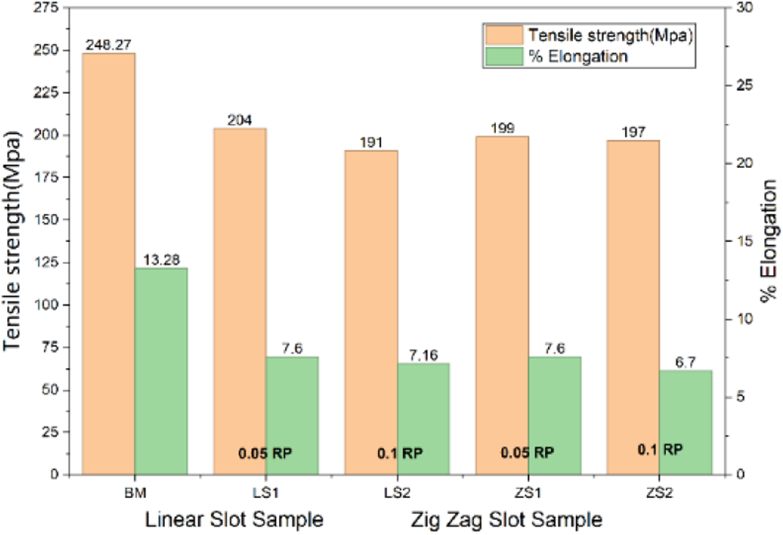
Tribological properties of processed composites.

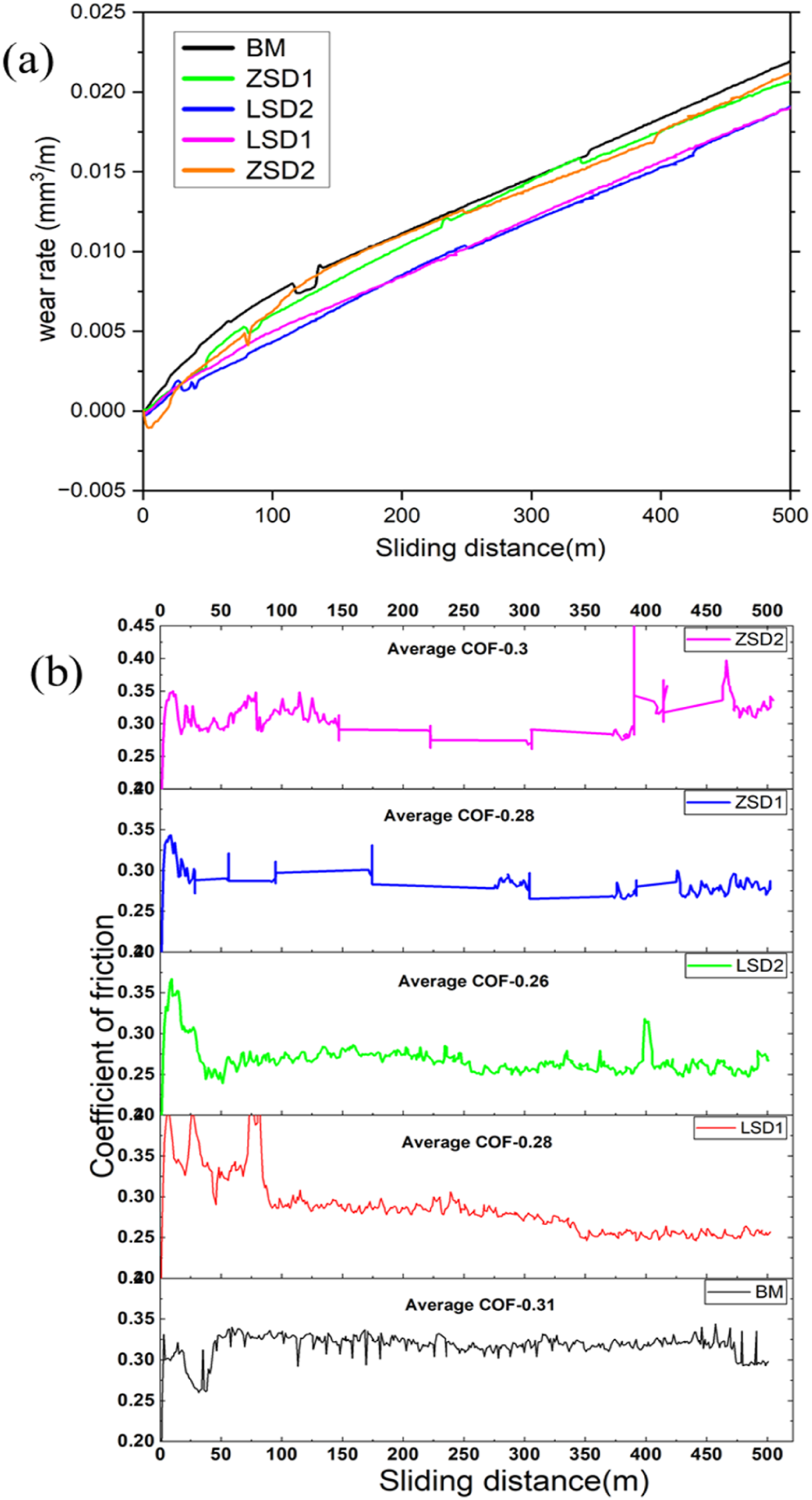
(a) Volumetric wear rate and (b) coefficient of friction (COF) of the as-received base material (BM) and the processed composite samples.
The variations in the coefficient of friction (COF) as a function of the sliding distance for the BM, LSD, and ZSD samples are shown in Figure 15(b), and the average COF values for each sample are presented in Table 4. According to the results, both the LSD- and ZSD-based composites exhibited a noticeably lower average COF than BM. Among these samples, the LSD composites processed at 0.05 RP and 0.1 RP exhibit lower average COF and lower fluctuations than those of the BM and ZSD samples during sliding, as shown in Figure 15 (b). This behaviour can be attributed to two factors. First, the FSP process produces a hardened surface layer that delays the onset of fatigue cracks and reduces debris formation. With fewer debris particles and a smaller real contact area, the frictional response became more stable.47,49 Second, the presence of MWCNTs further reduces friction because these nanotubes form a thin lubricating film during sliding, thereby enabling the composites to maintain a lower, more consistent COF.17,46,50
The SEM micrographs of the worn surfaces of the BM, LSD, and ZSD samples, as shown in Figure 16(a)–(d), indicate that the BM primarily exhibits abrasion, oxidation, and delamination as the dominant wear mechanisms. Micro cutting, ploughing, and grooves parallel to the sliding direction on the worn surfaces of the LSD and ZSD composites clearly indicated abrasive wear and delamination. This mechanism arises in the MWCNT/AZ31 composites during FSP because the magnesium grains are less likely to detach because the uniformly distributed MWCNTs act as lubricants that help stabilize the matrix grains.
48
Accordingly, Figure 16(a) and (b), showing the debris-generated wear became finer and significantly reduced in volume, respectively. Lower coefficient of friction and higher hardness effectively minimise the severity of abrasive wear. This wear mechanism is consistent with the findings reported by Singh et al. for the MWCNT/AZ31 composites.
17
SEM images of worn surfaces of (a) BM, (b) LSD processed with 0.05RP, (c) LSD processed with 0.1RP, (d) ZSD processed with 0.05RP, (e) ZSD processed with 0.1RP.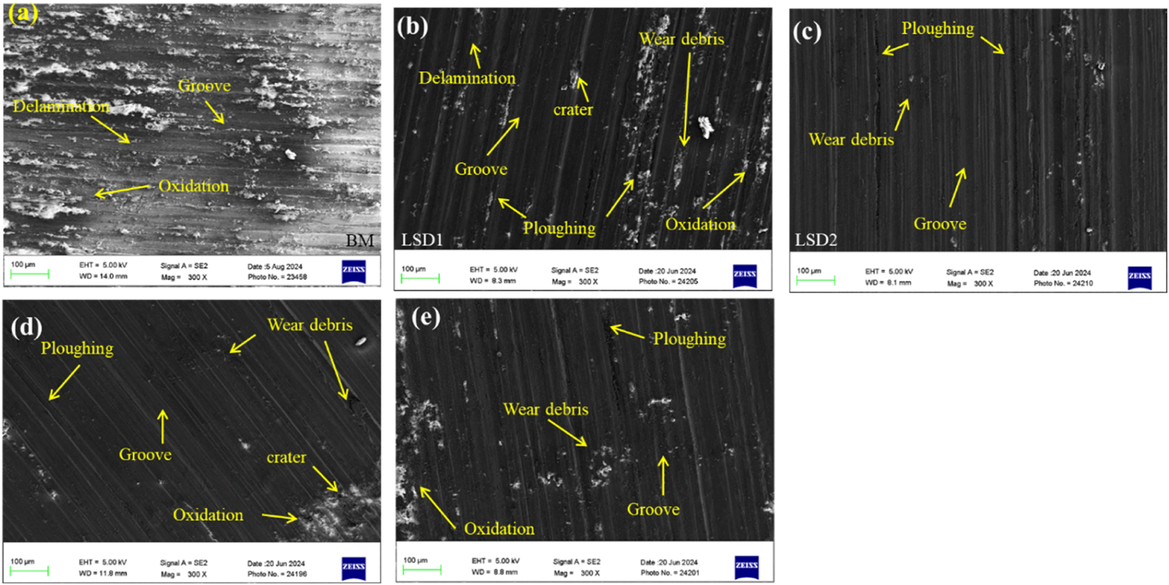
Conclusion
The current paper shows the MWCNT/AZ31-based surface composite successfully fabricated with the help of LSD as well as ZSD. After carrying out comprehensive investigations on microstructure as well as mechanical properties of prepared surface composites, the following points are concluded: • The SZ of surface composite was significantly refined from 33 µm BM to 2.65 µm (LSD) as well as 4.7 µm (ZSD). This refinement is attributed to particle pinning and is further enhanced by CDRX, which transforms the subgrains into stable equiaxed fine grains. • The microhardness was observed in the LSD sample at 100HV, followed by ZSD at 86.97 HV, both exceeding the BM’s at 50 HV. There represents a 74-100% improvement in the hardness of the surface composites as compared to BM, primarily owing to the presence of MWCNT particles and significant grain refinement. • Tensile strength and elongation achieved lower than the BM caused by residual stress relaxation and particle agglomeration. Although the surface composites retained up to 82% of their BM strength. • The LSD-based composites exhibited superior tribological properties compared with the ZSD-based composite and the BM. Grooves and ploughing show the abrasive wear mechanism in the LSD- and ZSD-based surface composite. • Defects such as tunnelling and wormholes were observed in the SZ of the processed ZSD-based composite, which can be attributed to the high flow stress of the BM and the entangled nature of the MWCNT powder. • Overall, the LSD strategy provided the best balance between particle distribution and property enhancement because it ensured uniform mixing of MWCNTs in the SZ.
Footnotes
Acknowledgements
The authors would like to thank the authorities of Pandit Deendayal Energy University (PDEU) and IIW-PDEU Welding Research and Development Centre, Gandhinagar, India, for providing the necessary support and infrastructure to carry out this work. The processing of samples was undertaken on a 3- axis automatic Vertical Machining Centre (by V. J. Badheka) procured under funding from the Indian Space Research Organization, Department of Space, Government of India, Bangalore (in collaboration with Space Application Centre, Ahmedabad) under the RESPOND program (Project number- ISRO/RES/4/567/09–10). Tribology tests were also performed in the Engineering Metallurgy lab of the Department of Mechanical Engineering, followed by the recording of worn morphology of wear surfaces. The authors also thank the Government Engineering College, Palanpur, for providing microhardness testing facilities.

Author contributions
All authors contributed to the study conception and design. The experimentation, material preparation, data collection, and analysis were performed by Vipul K. Patel, Harikrishnasinh Rana, Dinesh K. Patel and Vishvesh Badheka. Harikrishnasinh Rana and Pradip K. Gajjar contributed to additional characterisation. First draft of manuscript written by Vipul K. Patel and all authors provided valuable suggestions on previous versions of the manuscript. All authors read and approved the final manuscript. All authors have approved the manuscript for publication. I want to declare on behalf of all co-authors that the work described herein is original research that has not been published previously.
Funding
The authors received no financial support for the research, authorship, and/or publication of this article.
Declaration of conflicting interests
The author(s) declared no potential conflicts of interest with respect to the research, authorship, and/or publication of this article.
Data Availability Statement
The supporting data for this study’s findings are available from the corresponding author on reasonable request.