






Abstract
Hardware-in-the-loop (HIL) is a type of real-time simulation test that is different from a pure real-time simulation test due to a real component added to the loop. Since HIL includes numerical and physical components, a transfer system is required to link these parts. The transfer system typically consists of a set of actuators and sensors. In order to get accurate test results, the transfer system dynamic effects need to be mitigated. The fuel control unit (FCU) is an electro-hydraulic component of the fuel control system in gas turbine engines. Investigation of FCU performance through HIL technique requires the numerical model of other related parts, such as the jet engine and the designed electronic control unit. In addition, a transfer system is employed to link the FCU hardware and the numerical model. The objective of this study was to implement the HIL simulation of the FCU. To get accurate simulation results, the inverse and polynomial compensation techniques were proposed to compensate time delays resulting from inherent dynamics of the transfer system. Finally, the results obtained by applying both of the methods were compared.
1. Introduction
Hardware-in-the-loop (HIL) is a type of component testing method in which the physical component to be tested communicates with the numerical model of the rest of components. Through applying the HIL technique, a component of a system can be tested physically in almost real conditions. Not only can this test save time and cost, but also there remain no concerns about the test safety. The tested component is often an electronic control unit (ECU), since most dynamic systems, especially in aerospace and the automobile industry,1–3 have a main controller (ECU). Sometimes, HIL is an area of interest for evaluating the performance of other mechanical components in a system.4–8 To link the tested component to the numerical model, a transfer system is required. The transfer system consists of a set of actuators and sensors. So, to get accurate test results, the dynamic characteristics of the transfer system must be compensated.
Compensating the effect of transfer system dynamics has been studied in detail within the context of the related testing technique of real-time hybrid simulation.9–13 Real-time hybrid simulation is an actuator-based HIL technique that, so far, has been primarily considered for earthquake engineering systems.10,11 Hybrid simulation testing provides an alternative to the dynamic testing of structural systems by combining physical testing with numerical simulation. In hybrid simulation, the structure to be tested is divided into a numerical model, and a physical component that is too complicated to be modeled numerically. These two parts are connected through a hydraulic actuator that does not exist in the real physical system. The time delay caused by the hydraulic actuator introduces an equivalent negative damping that may lead to errors in the test results, thereby destabilizing the real-time hybrid simulation if not compensated properly. 12
The fuel control unit (FCU) is one of the key components in gas turbine engines; therefore, after designing and manufacturing a new set of FCUs, it is fundamental to test the set physically. In order to test FCUs, HIL combines the experimental testing of FCUs and the numerical simulation of other related parts, such as the designed ECU and jet engine model. In the real fuel control system, the required torque, which drives the FCU pump, is provided by a reductive gearbox connected to the main shaft of the jet engine. This pump provides the required fuel for combustion in the jet engine. In HIL simulation, the jet engine is modeled numerically; 1 thus, an actuator must be added to transfer command signals from the numerical part (jet engine) to the physical part (FCU). Here, an alternating current (AC) motor is employed in HIL as an additional system to transfer the required torque from the jet engine to the FCU pump. A flow meter is also used to measure the fuel flow rate and, therefore, its value is fed back to the numerical part.
In dynamic systems, such as the AC motor control system in this case, the time difference between the moment at which the input command is sent and the moment at which the system reaches this command is defined as time delay. As a result of the time delay caused by inherent dynamics in the AC motor and flow meter, the HIL simulation leads to inaccurate test results.
In order to compensate for these time-delay effects, several approaches have been proposed by researchers so far. These approaches can be categorized into two groups: those that modify command signals and those that correct the measurements. The former group consists of some approaches, such as inverse compensation, 14 which use a simplified discrete transfer function model for the transfer system, the derivative feed forward 15 and phase lead compensator 16 originating from control engineering practice in which the transfer system is treated as a time (phase) delay system and, by using analysis in the frequency domain, compensation parameters for these methods are determined. On the other hand, the latter group includes approaches such as emulator-based control (EBC), 17 which emulates the inverse of a transfer system not causally invertible such that the effect of transfer system dynamics can be mitigated by reformulating the problem as a feedback control problem, and also the Smith prediction, 11 which is an instance of a controller applying a built-in mathematical model of the controlled system. Moreover, delay compensation approaches that are based on a polynomial extrapolation can be in both groups.12,18 The polynomial method is intended to calculate predicted commands so that the actuator can achieve the command signal under actuator delay.
An equivalent discrete transfer function approach was proposed by Chen and Ricles
19
to analyze these actuator delay compensation approaches. By the discrete
One of the most significant advantages of the polynomial and inverse compensation over most other approaches, such as EBC and Smith, is that they are not model-based methods. In this way, they can operate from a desired initial condition with no prior knowledge of the plant dynamics. Moreover, the inverse method, which uses a simplified discrete transfer function, has several advantages. Firstly, transfer systems for aerospace engineering research often use digital controllers in which the inputs and outputs are sampled and recorded in discrete form. Also, in real-time testing, the integration algorithms are required to be programmed in discrete form. The discrete model can more realistically represent the data flow in real-time testing, as compared with a continuous model.
In this article, the FCU structure is described, and the transfer system and its time-delay model are estimated. Then, the polynomial extrapolation and inverse compensation approaches are proposed to compensate for time-delay resulting from the AC motor and flow meter in the HIL simulation of a jet engine FCU. Finally, the comparison between HIL simulation results of this study and the desired results is employed to verify the performance of the proposed delay compensation approaches in HIL simulation of the FCU.
2. Fuel control unit
The FCU is the most essential component of air gas turbine engines. It is a device designed to control the fuel flowing to the engine in order to maintain a constant turbine power speed and, thus, a constant engine speed. When an engine operates at its top speed, the FCU delivers the maximum fuel flow to the engine, and the engine generates the maximum amount of power available under the existing conditions.
The FCU consists of two separate sets: the hydraulic and control block. The hydraulic set controls the fuel flow rate to the engine’s combustion chamber based on information it receives from the control block set. A positive displacement gear pump receives fuel from a fuel tank and delivers it to the hydraulic block; then, the controlled fuel flow exiting the control block set is led to the combustion chamber by means of the hydraulic block set. The hydraulic block contains two fundamental valves: a flow-regulating valve and a pressure-regulating valve (see Figure 1). The flow-regulating valve receives engine speed commands through the FCU servomotor movement, which causes spool displacement in the flow-regulating valve. The pressure-regulating valve maintains a constant pressure differential across the flow-regulating valve by bypassing the excess fuel back to the engine fuel pump inlet. The pressure-regulating valve consists of a piston or spool that slides within the bore of a sleeve. When the engine operates below its maximum speed, the pressure regulator spool continually moves within the sleeve to maintain a constant pressure differential across the flow-regulating valve.
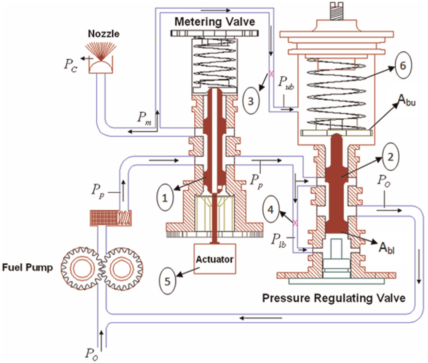
The fuel control unit components (1, 2: spools; 3, 4: upper and lower bidirectional control valve; 5: servo motor. 6: spring).
3. The hardware-in-the-loop test setup
HIL simulation is used to experimentally verify the response of some main elements of a control system. In HIL simulation of the FCU, the system is divided into two components: the FCU is tested experimentally (the physical component), while the rest of the system is modeled numerically (the numerical component). The HIL diagram of FCU performance is shown in Figure 2. After preparing all elements, such as the jet engine model and a proper ECU designed 1 according to the FCU model, the FCU test unit must be set up. So, to link the numerical part to the physical part, a transfer system is added to the control loop (see Figure 2). The transfer system utilized in the HIL test bench of the FCU consists of an AC motor and a flow meter. The AC motor transfers speed from the numerical model to the FCU pump, while the flow meter conveys the measured flow rate from FCU to the numerical model. The numerical model is run on a computer with suitable inputs and outputs. One output would be the speed control signal for the actuator, while the measured flow rate will be the model input. In order to control the AC motor speed, an inner control loop is designed, and an optical tachometer is used to measure and feedback it.
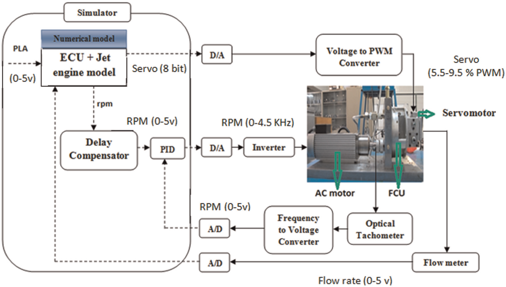
Hardware-in-the-loop test stand of the fuel control unit (FCU).
4. Transfer system
In this HIL setup, the transfer system consists of both the AC motor system and the flow meter. The AC motor control system consists of a variable frequency drive, a noise filter, an optimal tachometer and a frequency-to-voltage converter. The simplified model for the AC motor system was developed by the data-driven modeling approach that uses the test data.
In this study, the iterative prediction error minimization (PEM) method was applied to estimate the model parameters. 20 In an open loop control test, the response of the AC motor control system was measured experimentally by employing a square wave speed set point to the system and the corresponding speed was measured too. To control the motor, the experiment setup included a computer with an Advantech data acquisition card of PCI-1711. Here, the command was transmitted through the PC and the actual response was read from the tachometer by the card; then, a proper proportional-integral-derivative (PID) controller was selected to control the AC motor speed with the optical tachometer. By using the desired command signal and the output data measured in the open loop condition, the simplified model parameters of the AC motor control system were determined.
For real-time HIL testing, it has been shown that the time delay due to the transfer system dynamics may induce instability. To solve this problem using compensation methods, obtaining the transfer system model is necessary. Although the transfer system models are developed to describe the physical system as accurately as possible, they are sometimes too complicated for practical use. Simplifying assumptions are usually necessary to reduce the order of the transfer functions of the transfer system. Bonnet et al. 21 have pointed out that it is quite reasonable to assume that the transfer function is a first-order continuous system, thereby obtaining good results by the model and the experimental results for a real-time test. Reinhorn et al. 22 used a pure delay to model the transfer system. These types of simplified models for the transfer system have been shown to be useful for designing the control law and determining the parameters for compensation methods used in actuator delay and under real-time testing.
In the systems simulation and control laboratory, the effectiveness of the AC motor control system in time delay was investigated by comparing a sine wave command and its corresponding response in an open loop condition. It was shown that the time delay caused by the inner control loop model was approximated to the pure time delay of

The other part of the interface between the numerical and physical parts is the measurement system. The main effect of a sensor is to introduce considerable high-frequency noise content to the signal being fed back into the numerical part. This effect can be reduced by appropriate filtering, which, in turn, will introduce an additional component of pure time delay into the loop. The flow meter and its filter have a time delay (response time) of

Therefore, the total time delay is

In order to observe the effect of the transfer system on the HIL simulation of the FCU, a reference signal weighted sum of several sinusoids with amplitude adjusted to give a PLA (Power Level Angle) within the range of the equipment, as shown in Figure 3, was used. The simulation results of the FCU and jet engine model, without applying any delay compensation method, are shown in Figures 4 and 5. It can be seen that these results cannot be valid. Therefore, the transfer system effects must be mitigated by a compensation method.
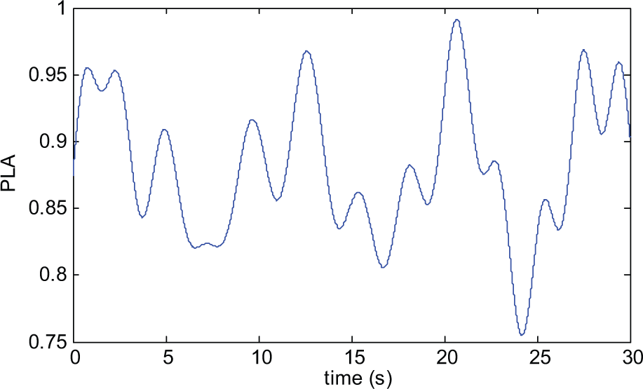
The reference signal weighted sum of several sinusoids with amplitude adjusted to give a Power Level Angle.
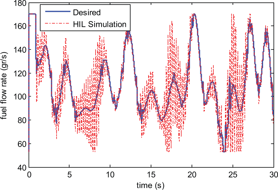
Hardware-in-the-loop (HIL) simulation result in the fuel control unit output without considering delay compensation.
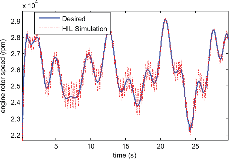
Hardware-in-the-loop (HIL) simulation result in the engine output without considering delay compensation and its comparison with the desired result.
5. Inverse compensation model
It can be understood from Figure 6 that if the command signal is affected by time delay, the response signal will be what is shown in the Figure 6. To compensate this time-delay effect, the command signal must be shifted forward.
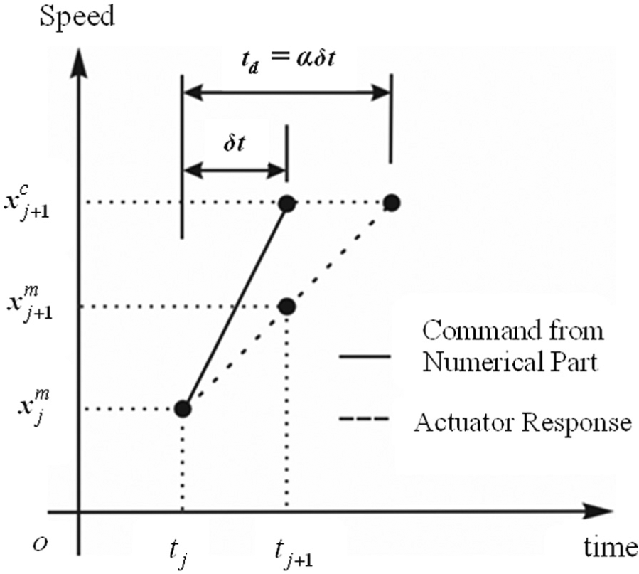
The idealized actuator response with time delay.
In order to minimize the delay effect of the transfer system, the inverse compensation method, which was based on simplified modeling, was introduced by Chen and Ricles.
14
In this approach, the idealization of actuator response under the command signal

By using Equation (4), the discrete transfer function

where

where

Thus, the measured signal
By rewriting Equation (6) in the form of a difference equation, the inverse compensation extrapolation form in the time domain will be

It can be realized from Equation (8) that computation of the compensated signal
6. Polynomial extrapolation
The forward prediction concept for delay compensation is presented in Figure 7. Here, the command signal
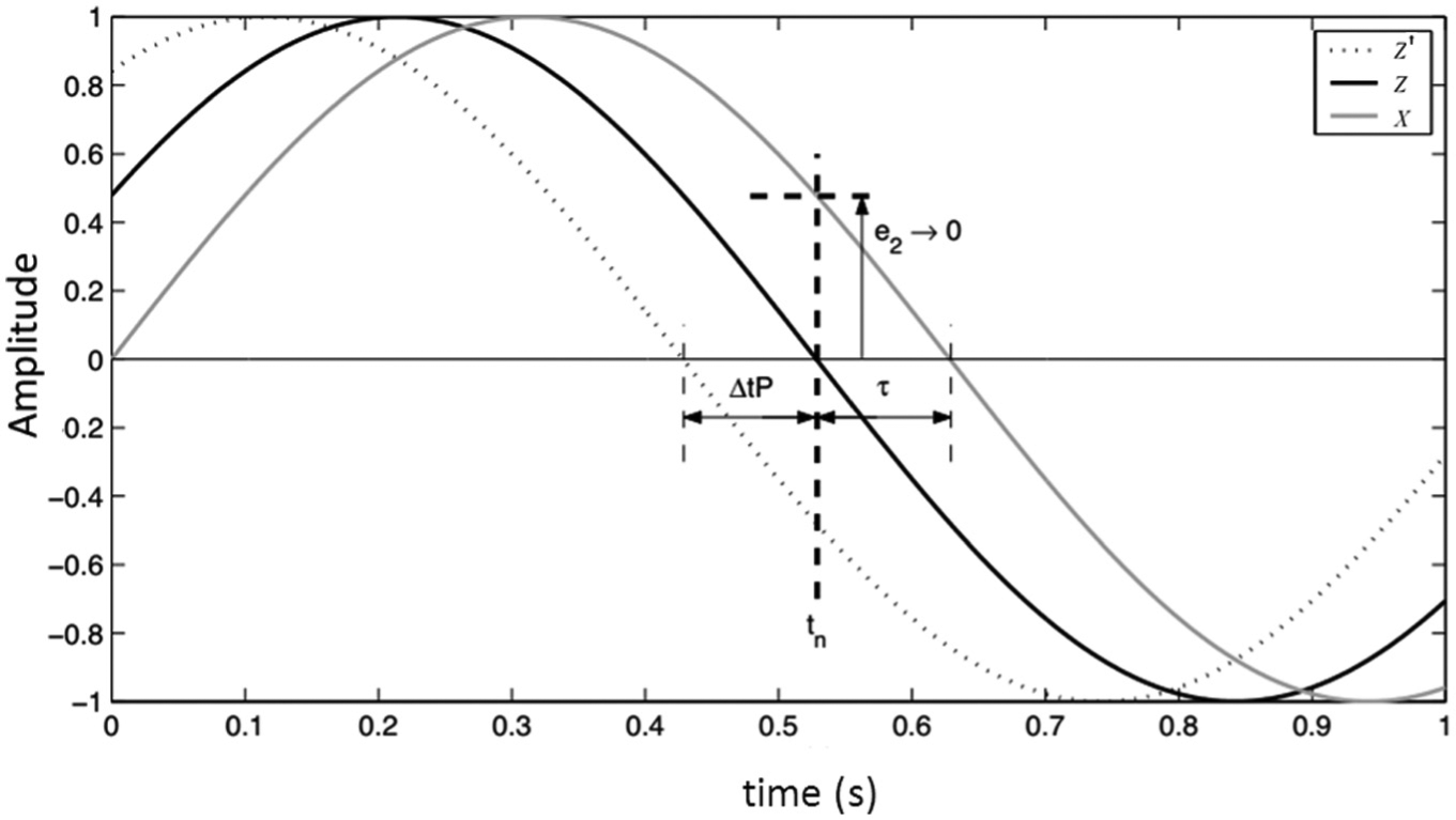
Delay compensation for transfer system dynamics by creating a forward predicted signal
In order to predict one step or several steps ahead of current time, a polynomial with a proper order can be helpful in obtaining an accurate prediction of future steps in approximation. A method for predicting command by using some previous time steps according to the values of some parameters, such as time delay and sample time size, was introduced by Horiuchi et al.
10
For instance, as shown in Figure 8, the future time step,

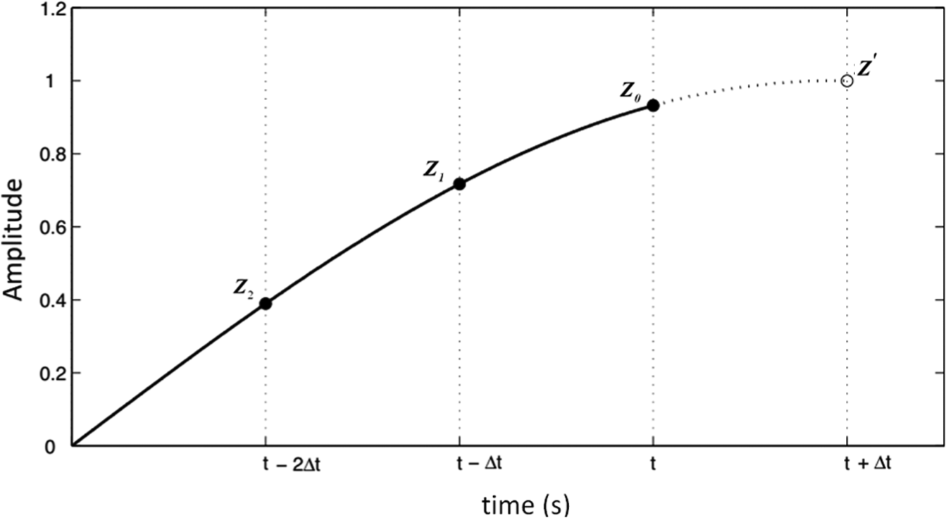
Single time-step prediction of
Selection of the proper

where

Minimizing the sum of the squares of the points offset from a curve is one mathematical procedure for finding the best fitting curve to a given set of points. To derive these relationships, the linear least-squares fitting technique was applied to provide a solution for finding the best fitting line through a set of points. This technique is the simplest and most commonly used form of linear regression. A polynomial in

If Equation (12) is an
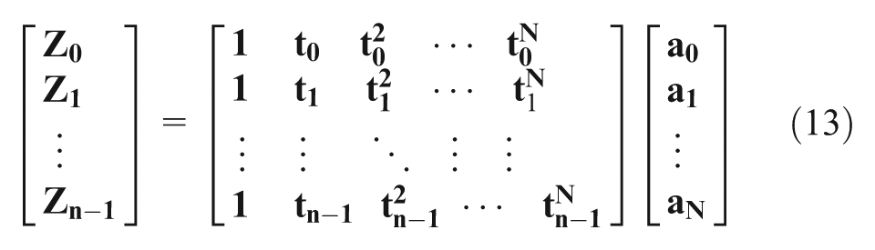
It can also be shown in vector format as follows:

After solving Equation (14) through premultiplying by the matrix transpose, such that

In the case that
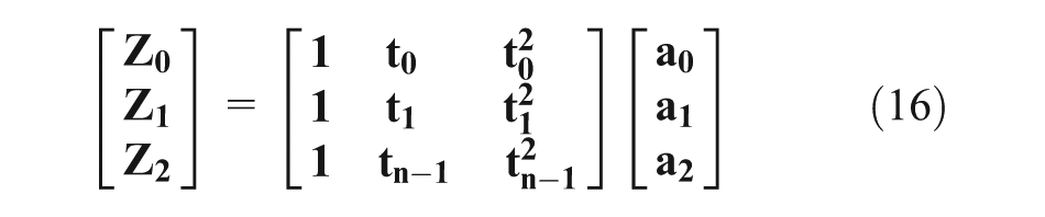
Assuming that
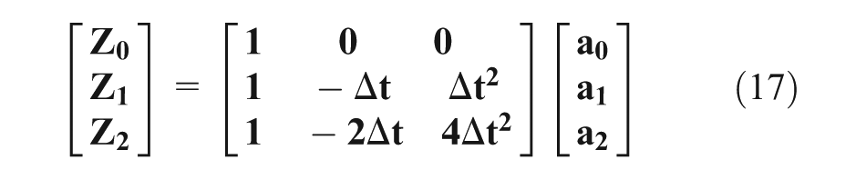
the predicted time step

where,

and

Evaluation of

This matches the one-step method coefficients in Equation (11). For

This matches the coefficients in Equation (20), although in a single operation. As a result, the coefficients

Thus, the polynomial extrapolation forward prediction is formed by the coefficients
7. Hardware-in-the-loop simulation results
Results demonstrated in Figures 3 and 4 showed that the transfer system time delay was not negligible; so, applying delay compensation approaches such as the inverse and polynomial methods could result in a significant improvement in the accuracy of simulation. The objective of employing these compensation techniques is to achieve synchronization between the desired interface command of the numerical models and the measured value of the transfer systems. Therefore, this time, the HIL simulation was performed in the presence of the inverse compensation and polynomial approaches.
The model of the jet engine, the ECU, and compensation for actuator dynamics are implemented in Simulink using continuous time systems. Through the fourth-order Runge–Kutta solver of Simulink, numerical integration was performed. Finally, the HIL simulation results were compared with the ideal results by considering the proposed compensation methods.
As discussed in Section 5, the delay constant,


In addition, according to Section 6, the polynomial coefficients related to the total time delay (

By this polynomial, the future step can be predicted to compensate for the time-delay effect introduced by the transfer system.
By using Equations (25) and (26), which are related to the inverse and polynomial compensation methods, respectively, the time-delay effect introduced by the transfer system could be compensated. Therefore, as shown in Figure 2, the block related to this transfer function was used to equalize the signal command coming from the numerical part to the signal input received by the FCU approximately. By applying the reference input in Figure 3 and performing this simulation with the proposed delay compensation methods, the results of the FCU and jet engine model were obtained as depicted in Figures 9 and 10. The desired outputs in these figures were the numerical simulation results of the fuel control system model implemented in Simulink without considering time delay caused by the transfer system and, therefore, without considering delay compensation. Good tracking between the desired and HIL simulation results in Figures 9 and 10 indicated that the selected compensation methods could effectively compensate for the transfer system delay.
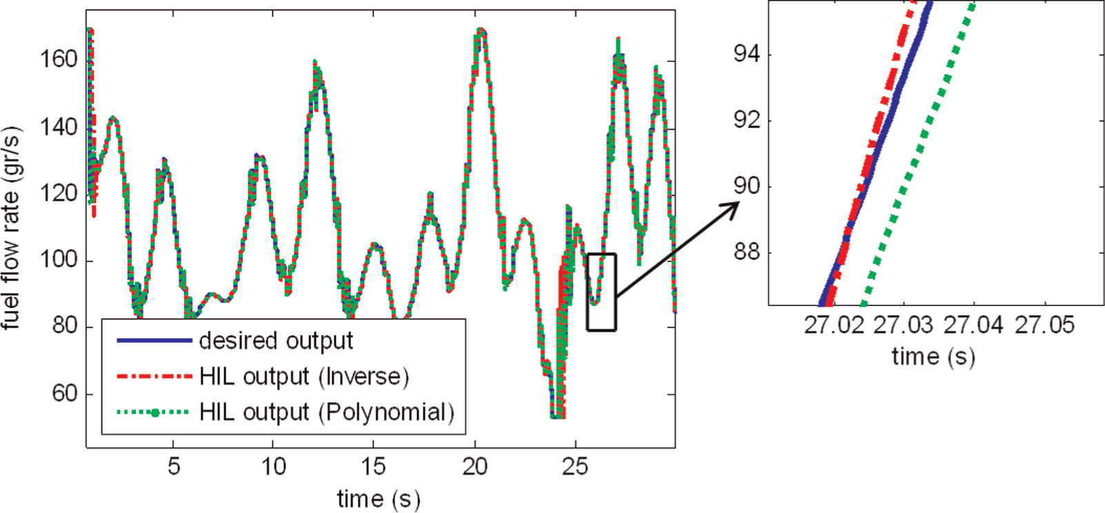
Hardware-in-the-loop (HIL) simulation result in the fuel control unit output considering delay compensation and its comparison with the desired result.
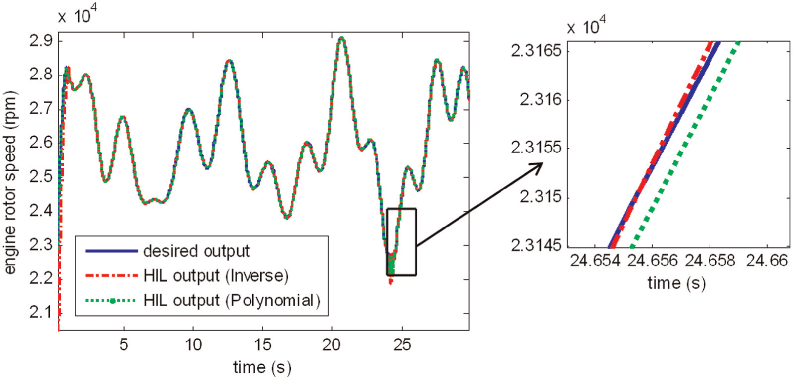
Hardware-in-the-loop (HIL) simulation result considering delay compensation in the engine output, and its comparison with the desired result.
In this study, the Tracking Indicator

where


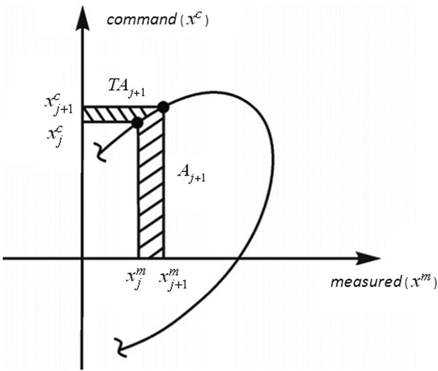
Definition of area
At the beginning of the test, the enclosed and complementary areas had the initial values of zero. The calculation of
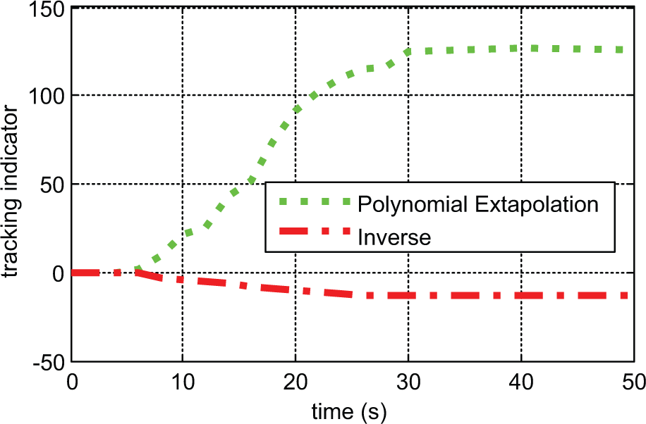
Tracking indicator of real-time hardware-in-the-loop simulation using different compensation methods.
The positive value of the tracking indicator in Figure 12 indicated that the polynomial extrapolation method introduced a phase lead and, hence, over-compensation. The inverse compensation had a much smaller magnitude for the tracking indicator. The tracking indicator was negative in value and, therefore, implied that a slight phase lag occurred during the test for the inverse compensator. The results in Figure 12 implied that the inverse compensation method had a better performance during the test given the fact that the phase error was smaller in its test results.
8. Conclusion
HIL is an efficient and safe way of component testing in comparison with more common testing methods. The purpose of this study was to introduce a new HIL platform for testing the FCU. The simulator included an engine model, an ECU and a transfer system for connecting to the FCU. In this HIL simulation, the main problem was the time delay introduced by the transfer system. The polynomial and inverse compensation strategies were applied to mitigate the transfer system effects. This study showed that HIL was a suitable simulation method for the development of the FCU. From HIL simulation results, it was also observed that the inverse technique was more accurate than the polynomial method for compensating for the time delay of the transfer system in HIL simulation.
Footnotes
Funding
This research received no specific grant from any funding agency in the public, commercial, or not-for-profit sectors.