






Abstract
In the hardware-in-the-loop (HIL) simulation of the fuel control unit (FCU) for aero-engines, the back pressure has a great impact on the metered fuel, thus influencing the confidence of the simulation. During the practical working process of an aero-engine, the back pressure of the FCU is influenced by the combined effect of the pressure of the combustion chamber, the resistance of the spray nozzles, and the resistance of the distribution valve. There is a need to study the the mimicking technique of FCU back pressure. This paper models the fuel system of an aero-engine so as to reveal the impact of FCU back pressure on the metered fuel and come up with a scheme to calculate the equivalent FCU back pressure. After analyzing the requirements for mimicking the pressure, an automatic regulating facility is designed to adjust the FCU back pressure in real time. Finally, experiments are carried out to verify its performance. Results show that the mimicking technique of back pressure is well suited for application in HIL simulation. It is able to increase the confidence of the simulation and provide guidance to the implementation of mimicking the FCU back pressure.
1. Introduction
Hardware-in-the-loop (HIL) simulation enables the operation and testing of actual components of a system along with virtual computer-based simulation models of the rest of the system in real time.1,2 In this way, the quality of testing is enhanced, thus shortening the design cycle and improving the reliability of the tested components.
The fuel control unit (FCU) is a fuel-metering device that regulates the fuel flow to the engine in accordance with the pilot’s demand, ambient environmental conditions, and other related factors. It is a crucial part of engine control system. Usage of HIL simulation for testing the aero-engine FCU has been reported in several researches for different purposes. Montazeri-Gh et al.3,4 investigated the complex interaction between the FCU hardware and overall aircraft performance, while Karpenko and Sepehri 5 objectively tested novel fault tolerant control and diagnostics algorithms for fluid power actuators. Principles of the fuel control are presented by Tudosie, 6 among which the type with constant fuel differential pressure and an adjustable fuel window is most widely used. However, the performance of the electro-hydraulic FCU can be influenced by changes in the characteristics of the operating environment and by changes in the system parameters. 3 As a result, whether the differential pressure across a fuel-metering valve could maintain constant remains a question. You et al. 7 investigated the influence of fluctuant inlet pressure on the characteristics of the FCU for a ramjet. Gaudet 8 presented an approach for controlling fuel flow in which the differential pressure across a fuel-metering valve is regulated by simultaneously varying the pump displacement and a small amount of bypass flow.
In the practical fuel system of an aero-engine, fuel is injected into combustion chambers through the FCU, fuel distribution valve, and spray nozzles. So, the back pressure of the FCU is equal to the sum of the back pressure of the spray nozzles, which is the outlet pressure of the engine compressor or the burner pressure, and the pressure drop of the fuel distribution valve as well as the spray nozzles. However, they both change with the operating state of the aero-engine. According to some researches,9,10 fuel regulated by the FCU is closely related to its back pressure. Regulating effects differ even in cases of the same metering valve opening but with different back pressure, which influences the confidence of the simulation. So, it is necessary to adjust the back pressure of the FCU in real time. A common way to simulate the pressure is to use a throttle valve with either a fixed orifice or a manually adjusted orifice. It is readily apparent that its real-time performance cannot be guaranteed, which brings about new approaches. One of them is to simulate the atmospheric environment of the combustion chamber. This approach requires complicated devices that are of high cost. A much simpler way is to design an automatically adjusted valve that regulates the back pressure of the FCU according to the real-time engine state.
In this paper, mimicking technique of back pressure that is used in HIL simulations of FCUs for aero-engines is studied. In Section 2, the mathematical model and AMESim model of the fuel system are established, which reveal the working principle of each component. Then, the effect of the FCU back pressure on metered fuel is investigated with the AMESim model in Section 3. Also, decisive factors of FCU back pressure and its calculation scheme are discussed in this part. Afterwards, requirements for simulating back pressure are put forward and an automatic regulating facility is finally designed in Section 4. Finally, in Section 5, experiments are conducted to verify the performance of the facility and its application in the HIL simulation.
2. Modeling of the fuel system
In order to know how the FCU works, how its back pressure changes, and how it influences the metered fuel, each component of the fuel system should be analyzed. Taking a certain turbofan engine, for example, its fuel system includes a gear pump, FCU, fuel distribution valve, and spray nozzle, while the FCU includes a metering valve, a pressure drop valve, a fuel return valve, and a pressure rising valve, shown in Figures 1 and 2. The gear pump is driven by a high-pressure turbine after changing shaft speed by the gearbox. It generates flow with enough power to overcome pressure induced by the load at the pump outlet. The electro-hydraulic servo valve controlled by the electronic control unit (ECU) changes the pressure of the control chamber of the metering valve, thus changing its displacement, which is then acquired by an LVDT displacement sensor and sent to the ECU for closed-loop control. 11 There is a linear relationship between the opening area and the displacement of the metering valve. The pressure drop valve senses the pressure at the inlet and outlet of the metering valve and adjusts the control fuel pressure of the fuel return valve, so as to adjust the displacement of the return valve, therefore adjusting the quantity of return fuel. If the pressure difference increases as the pump speed rises or the opening of the metering valve becomes smaller, the pressure drop valve feels the change of pressure difference and moves upwards, decreasing the control fuel pressure of the return valve. This leads to the upward movement of the return valve, resulting in the increase of return fuel and therefore the decrease of metered fuel. In consequence, the pressure difference is approximately held constant. Given this, fuel passing through the metering valve is only decided by its opening area, which means that the ECU is able to control the fuel quantity by controlling the displacement of the metering valve. The pressure increasing and the shut off valve act like “hydraulic resistance,” increasing the fuel pressure. Fuel metered by the FCU is then distributed by the fuel distribution valve and sprayed into the combustion chambers.
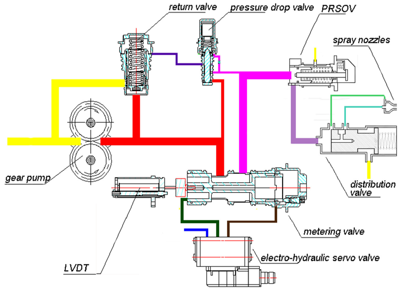
Components of the fuel system. PRSOV: pressure raising and shut off valve.

Schematic diagram of the fuel system. PRSOV: pressure raising and shut off valve; FCU: fuel control unit.
2.1. Mathematical model
2.1.1. Gear pump
The relationship between the fuel

where
2.1.2. Fuel-metering valve
The metering valve is the key component of the FCU, shown in Figure 1. It controls the fuel through the combustion chamber, called the metered fuel and denoted by

where
2.1.3. Pressure drop valve
The pressure drop valve maintains the difference of

where

Structure of the pressure drop valve.
2.1.4. Fuel return valve
The fuel return valve transmits the spare fuel to the inlet of the gear pump, whose structure is shown in Figure 4. There is a center hole in the return valve, through which a portion of the inlet fuel of the metering valve flows into the pressure drop valve and then combines with the outlet fuel of the metering valve, forming a “hydraulic potentiometer” whose working medium is the inlet fuel of the metering valve.
12
Fuel that flows through the center hole, denoted by

where

where

Structure of the fuel return valve.

where

where
Considering the fuel continuity, there is the following:

2.1.5. Pressure raising and shut off valve
The pressure raising and shut off valve, abbreviated as PRSOV, works as a “hydraulic resistance,” increasing the fuel pressure and shutting off the fuel sometimes. Figure 5 displays its structure.

where

where
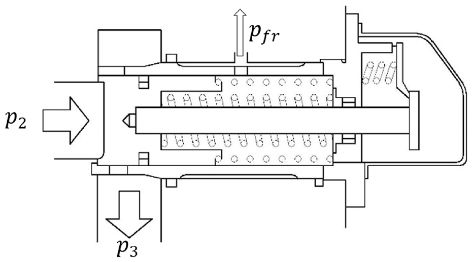
Structure of the pressure raising and shut off valve.
2.1.6. Fuel distribution valve and spray nozzles
The fuel distribution valve distributes fuel into two kinds of combustion chambers, the first called the pre-burner and the second called main combustion chamber,
13
represented by
2.1.7. Steady-state model of the fuel system
Based on the equations stated above, the model that relates one variable to another can be derived. Take the inlet fuel pressure of the metering valve,
Substituting (3) into (5), then:

Inserting (11) into (4) leads to the following:

where
Substituting (6) into (7), then:

Inserting (2) and (13) into (8) and considering that

where

Combining (12) with (14) and eliminating

This equation demonstrates the relationship between the inlet and outlet fuel pressure of the metering valve, namely,
Given that fuel through the distribution valve and nozzle is continuous, the combined effect of the distribution valve and nozzle can be represented with an equivalent throttle facility, called “facility 1.” So, there is the following:

where
Similarly, fuel through the PRSOV and facility 1 is continuous. We can use another equivalent facility, called “facility 2,” to express their joint effect. Substituting (9) into (10), then combining with (16):

where

Equation (17) and (2) present the same thing, which yields the following:

where

Solving (15) and (18), the relationship between

In brief, it can be clearly seen from Equation (15) that the pressure difference of the pressure drop valve will not always remain constant, resulting in the change of the metered fuel even in the case of fixed
2.2. AMESim model
Since the mathematical model involves many variables and parameters, it is not likely to be comprehended intuitively and it is not convenient to get or display all variables, such as force, displacement, flow resistance, and so on. So, an AMESim model may facilitate the research. After analyses of the structure of each component, the model is established in Figure 6.15,16
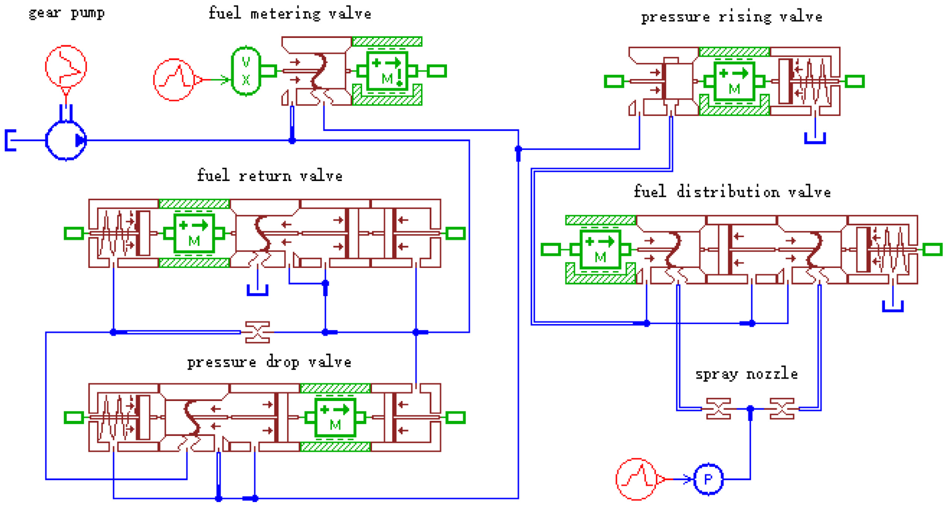
AMESim model fuel system.
3. Effect of the fuel control unit back pressure on metered fuel
3.1. Effect of the nozzle back pressure on metered fuel
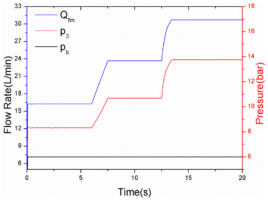
Firstly, the situation (denoted as situation 1) of the fixed opening of the metering valve (denoted as

Variables in situation 1. (Color online only.)
3.2. Relation between FCU back pressure and nozzle back pressure
First considering the case in Section 3.1, the FCU back pressure
3.3. Calculation scheme for FCU back pressure
The results gained in Section 3.2 are on the premise of fixed
From Equation (16), the total pressure drop of the fuel distribution valve and spray nozzles, denoted as

It is readily apparent that

where the subscript D denotes the specific value of

where

where m can be selected or adjusted based on actual situations, usually ranging from 1/12 to 1/2.
Consider the situation in Section 3.2. Selecting a steady point where

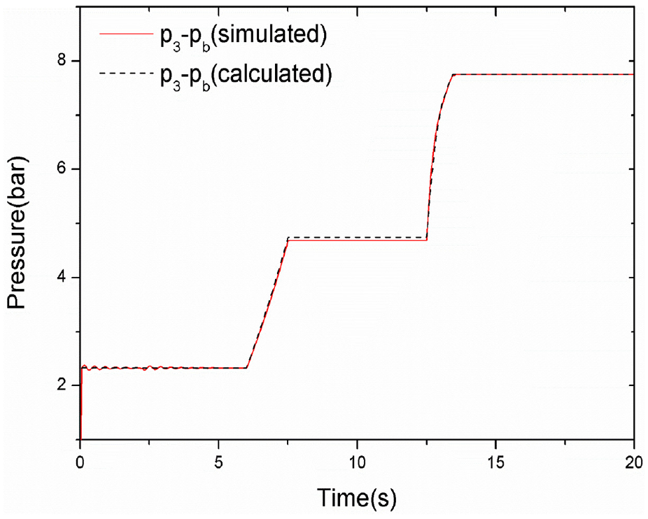
Calculated fuel control unit back pressure. (Color online only.)
4. Mimicking scheme for fuel control unit back pressure
In this section, we talk about how to design a facility that regulates
4.1. Requirements for the mimicking of FCU back pressure
Starting with requirements for the settling time of
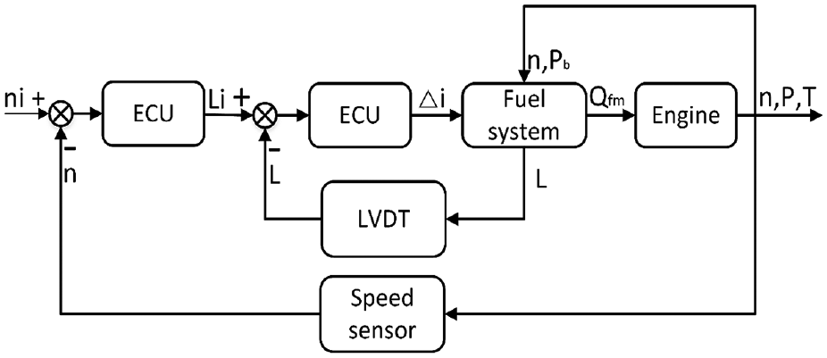
Schematic diagram of the engine speed control loop. ECU: electronic control unit.
So, integrated with Section 3, for the requirements for simulating
4.2. Design of the automatic regulating facility
Coming next is the design of the automatic regulating facility based on the requirements described in Section 4.1. The working principle of the facility is shown in Figure 11. It is also comprised of two control loops. A throttle valve is installed at the outlet of the FCU, the opening of which can be adjusted by the valve rod. A motor is attached to the valve, turning the valve rod. The displacement of the rod, namely the position of the valve, is acquired by a permanent linear contactless displacement (PLCD) sensor, which is installed normal to the rod sent back to the controller. Fuel flows through the valve and thus generates pressure. The pressure is then collected by a pressure sensor and sent to the controller. Together with the instructed pressure calculated with Equation (24), an instructed position of the valve is figured out. Comparing it with the real position from the PLCD sensor, the deviation generates pulse signals that adjusts the valve rod so as to changes the valve opening, thereby regulating the fuel pressure. Finally, the automatic regulating facility comes out, as shown in Figure 12.
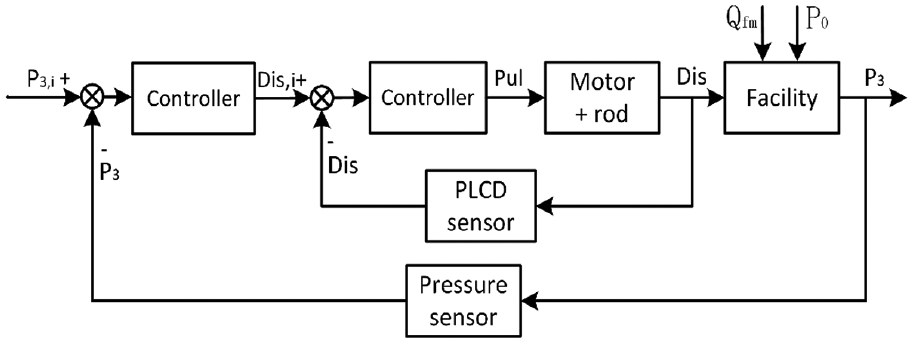
Principles of the automatic regulating facility. PLCD: permanent linear contactless displacement.

The automatic regulating facility. 1: motor; 2: rod; 3: magnetic ring; 4: valve; 5: permanent linear contactless displacement.
5. Hardware-in-the-loop simulation based on fuel control unit back pressure
Now that the automatic regulating facility of the FCU back pressure has been designed, it is time to carry out experiments for the purpose of validating its regulating ability and its application in HIL simulations. The test platform is as shown in Figure 13.
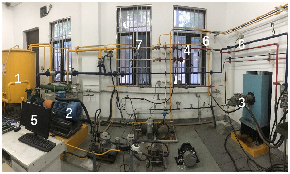
Hardware-in-the-loop simulation test platform. 1: fuel tank; 2: booster pump 3: fuel control unit; 4: automatic regulating facility; 5: controller; 6: pressure transducer; 7: flow meter.
5.1. Validation of the regulating ability of FCU back pressure
Keeping the metered valve at the maximum opening and adjusting the instructed
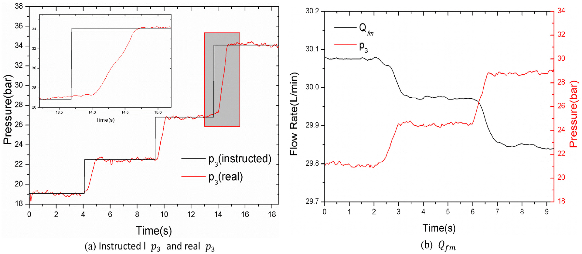
Variables in situation 3. (Color online only.)
In addition, the black line in Figure 14(b) shows the change of
5.2. HIL simulation of a FCU based on the mimicking technique of back pressure
In order to apply the mimicking technique to practice and verify its performance, a HIL simulation (denoted as situation 4) is carried out. Adjusting the instructed rotational speed from idling to maximum step by step, with the blue dashed line in Figure 15(a), the real engine speed shown with the red line varies correspondingly and settles down in complete agreement. Beyond doubt this is a result of the change of metered fuel, displayed with a black line.

Variables in situation 4. (Color online only.)
6. Conclusion
This paper studies the mimicking technique of back pressure, which is used in HIL simulations of FCUs for aero-engines. Firstly, it establishes models of the fuel system, which reveals the working principle of each component. Then, the effect of FCU back pressure on metered fuel is investigated with the AMESim model, and it is found that the metered fuel reduces with the increase of back pressure. Afterwards, the determinants of FCU back pressure are discussed, thus coming up with the calculation scheme for its application in HIL simulations. After that, the mimicking scheme for FCU back pressure is established. The requirements for simulating the pressure are put forward before we design an automatic regulating facility. Finally, experiments are conducted to verify the performance of the facility and its application in the HIL simulation. Results show that throughout this simulation, the settling time of FCU back pressure controlled by the automatic regulating facility for a large step change is no more than 1 s and its steady error is within 2%, which proves its application in the HIL simulation and increases confidence thereof.
Footnotes
Funding
The authors disclosed receipt of the following financial support for the research, authorship, and/or publication of this article: This work was supported by Postgraduate Research & Practice Innovation Program of Jiangsu Province (KYCX19_0186).ss
