
Abstract
The design of metallic card clothing, which is one of the most important devices in the textile industry, has always been based on operational experience. With the development of types of fibers and the requirements for the quality of yarns, those principles concluded by engineers seem to be losing their efficiency. Recent research found that airflow played an important role in the card process, which means airflow should be carefully studied. Computational fluid dynamics (CFD) simulation greatly helps in the analysis of airflow because the gauge between carding elements is too narrow to put in any measuring device. In the present study, with the help of CFD simulation, the air around different carding clothing with varied tooth depth was analyzed. It was concluded that the carding efficiency improvement in card clothing with lower tooth depth may be related to more concentrated air velocity at the tooth tips. This resulted in more probabilities that fibers would get through the cylinder surface at the teeth tips, so that the fibers could be caught by flat-top needles more efficiently. With this assumption, a new generation of card clothing called “double teeth” containing two teeth in a single section has been invented. The new configuration design of card clothing was then applied in several spinning mills on an industrial scale for experiments. The results showed about a 30% improvement in production at the same quality level as conventional card clothing, which implied the usefulness of the newly applied principles related to airflow. Despite the difficulty in the study of the complex carding process, the new airflow analysis method has shown an optional and worthwhile way of thinking that could make a difference in future research in the textile industry.
Carding is one of the most important processes in the spinning of fibers in which card clothing plays such an important role that it is called the “heart of the carding machine.” Due to the varied fibers and yarn quality requirements, various types of carding clothing are made in different sizes and shapes, especially metallic card clothing (MCC) made of steel ribbons. Despite the complexity of the carding process, the shape of the teeth retains a similar construction, which contains a “straight face” with a “bottom arc” tangent to it (Figure 1). As a result, the complete shapes are very similar to those of band saw teeth applied to cutting woods. In the past decades, in order to improve the carding quality in the main carding region, engineers have tried to shorten the distance between the tips and the blade bottom of the MCC, which is called the “tooth depth” (marked in Figure 1 as “h”). 1 It made sense and was considered as one of the most important design principles of recent decades. 2 The reason for the improvement was not so clear, but it may be related to the improved probability that fibers would be caught by flat-top needles or the increase in doffer efficiency because fibers are believed to prefer to stay at the top of the teeth rather than the bottom when a lower height card clothing is applied. However, when “h” was designed to be less than 0.3 mm, a great number of production problems happened, including punching and heat treatment problems, which result in stability that is too poor to keep the cost at an acceptable level. Another way to improve the card efficiency is the improvement of the points per square inch (PPSI). 3 However, the fibers are too weak to be operated by a common-shaped card clothing with PPSI that is too high. 1 This is a risky way to increase the carding efficiency because of the increasing possibility of fiber breakage, which is harmful to the quality. As a result, innovations in the structure of the teeth to avoid these drawbacks have been introduced in recent years.
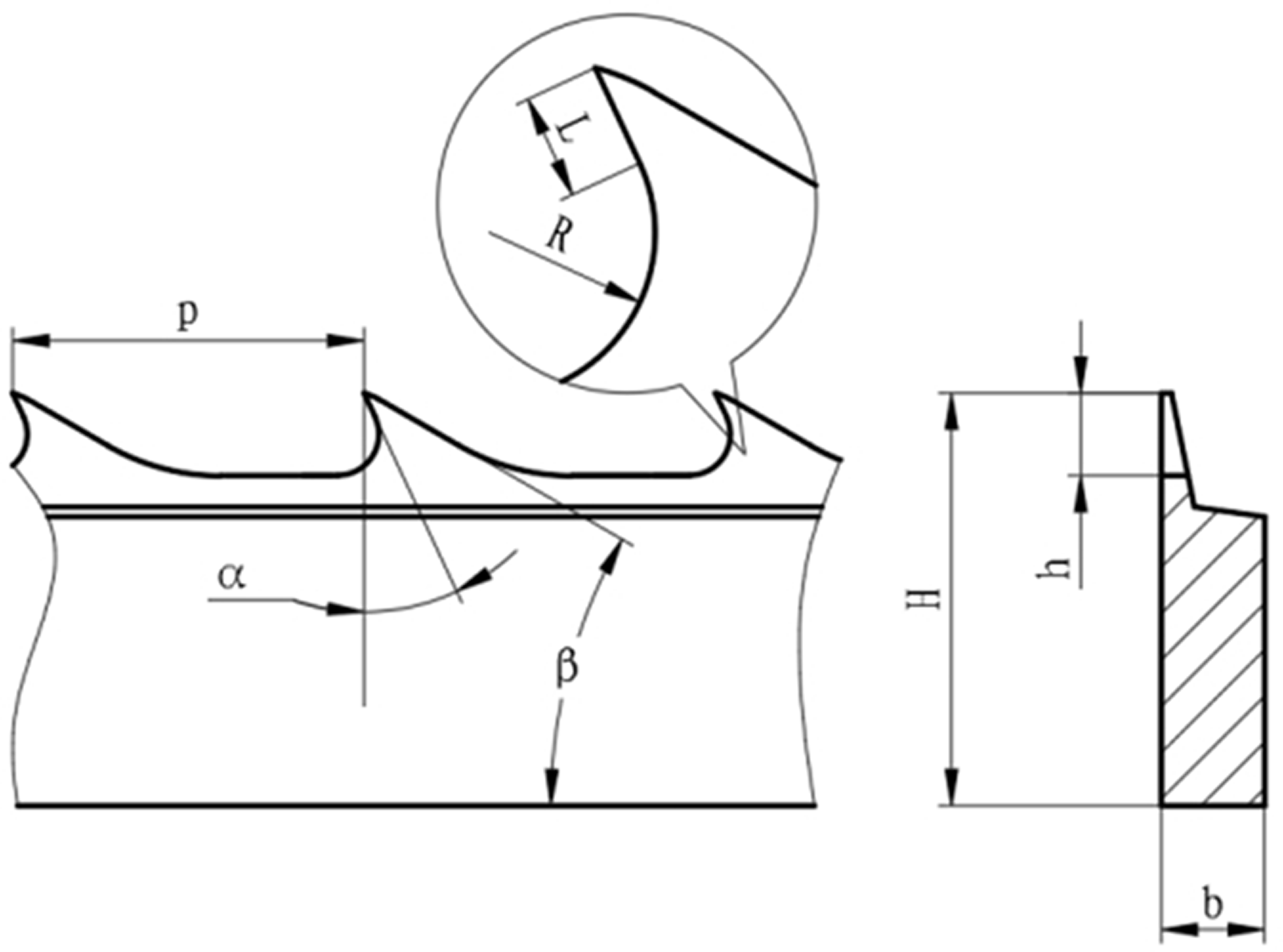
A simplified engineering drawing of conventional metallic card clothing. L: straight face; R: bottom arc; p: teeth pitch; α: working angle; β: back angle; H: total height; b: width of the row; h: teeth depth.
With the excellent imagination of global engineers and experimenters, a few new special tooth shapes were invented to solve these problems.4–9 However, these innovations were only ideas, and card clothing designed by these ideas needs a great number of experiments and correction steps before it becomes a new product. The classic design principles seem to be losing their significance while new principles are not established effectively yet. This will be the main limitation to the development of the carding process.
To explore some new principles and find some new tooth shapes, a close study of the carding mechanism is worthwhile. However, it is difficult to study due to many reasons, one being the insufficient understanding of the airflow surrounded the surfaces of cylinders in a carding machine, which will influence the fiber configuration on the teeth. The common study method of establishing a set of sensors did not work here because of the space being too small in these significant regions, 10 especially for the main carding area with a gauge less than 0.3 mm. Because of the large space in the cylinder–doffer interface, high-speed photography and image processing were used to study aerodynamics. 11 The results indicated the importance of understanding the airflow in a carding machine. This meant it may be necessary to study the airflow in the same significant region, which was referred to as the cylinder–flat-top interface.
Computational fluid dynamics (CFD) has been widely used in many industrial applications that involve complex airflow. It was introduced to the textile industry as an important and effective method to optimize the spinning process. 10 However, these studies focused on the relationship between airflow and the behaviors of fibers, but paid little attention to the structure of card clothing, which may affect the airflow.12–13 Only a few studies have shown the relationship between the design of card clothing and the airflow.
With a three-dimensional numerical simulation of airflow in the carding region, He 14 tried to explain the efficiency improvement in the misaligned-teeth card clothing and found that the reason was the turbulence flow. It was found that the airflow between the carding elements was strong enough to pull single fibers out of tufts, which showed the importance of airflow around the teeth beyond the traditional imagination and implied the possibility of designing a method developed depending on airflow rather than the mechanical effects between fibers and carding elements.
In this article, an improved simulation developed from He 14 will be established with a few improvements to meet real industrial requirements. With the intensive study of airflow surrounding the surface of carding clothing, a new assumption associated with velocity distribution perpendicular to the teeth forward has been created. Fiber dynamics were not investigated because of their complexity and extremely light fiber mass, in opposition to the lower cost/performance ratio for industrial requirements at present.
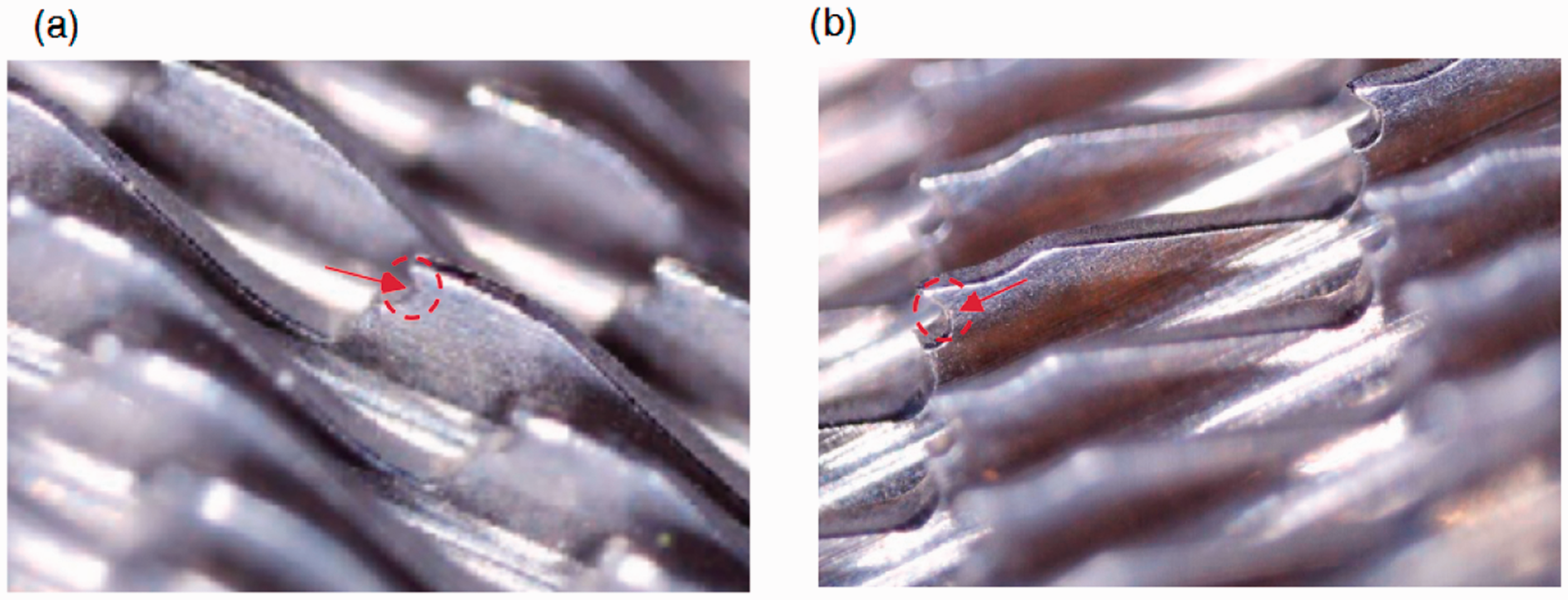
Based on the above idea, several new types of MCC were designed and analyzed with the help of CFD. Most of the designs were abandoned after comparison with the conventional card clothing with its tooth depth of 0.2 mm, while a card clothing with two teeth in one section, named “double teeth,” was chosen for this work. 15 The tooth profile is shown in Figure 2 with the optical micrograph of the real products. This design was then modified at different PPSI to meet the requirements in different applications in several spinning mills. The carding results were collected over several years with help of detection analysis and engineers’ statistics in different spinning mills. The results were analyzed to estimate the improvements in the carding process when the double teeth were applied. A comparison of the manufactural stability with teeth hardness variation as its index was also carried out to estimate the production stability of the new generation of card clothing. An experiment reported in the patent CN208071862U also showed the importance of airflow when the double teeth were applied. 16 Huang 16 applied several wind tunnels in the main cylinder to bring more airflow to the interface of the carding teeth and flat-top needles, guiding the inner fibers to the teeth tips. The improvement in card efficiency also showed that fiber distribution around the teeth has an impact on the carding efficiency. It is proof of the design idea of the double teeth.
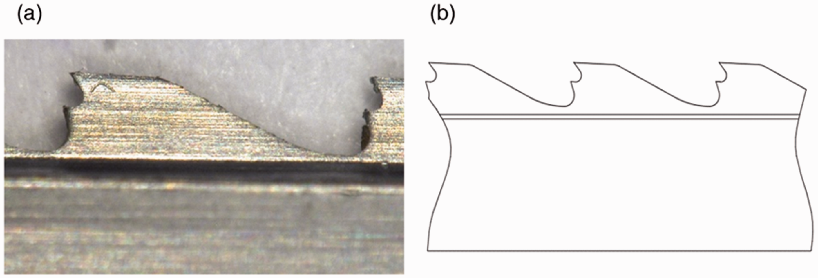
The structure of a typical type of double teeth card clothing: (a) an off-line optical micrograph; (b) a brief design drawing of the tooth profile.
Design and experiments for double teeth metallic card clothing
Model analysis by CFD
The simulation fluid geometric model is showed in Figure 3 with a simplified repeat unit between the cylinder domain and the flat-top domain. With the rotationally symmetric boundaries, it could be regarded as an approximate model of the whole main carding region. The arrangement of flat-top needles was uniform in order to simplify the simulation. Even though the structure of the flat top would affect the carding process, in this article it was taken as an invariant in order to study the change in airflow when the cylinder teeth were applied in different structures. The carding gauge was conferred in the carding to be the most important processing parameter, which was a constant value during the entire investigation. These results Could be an important reference in the design of a new type of card clothing.
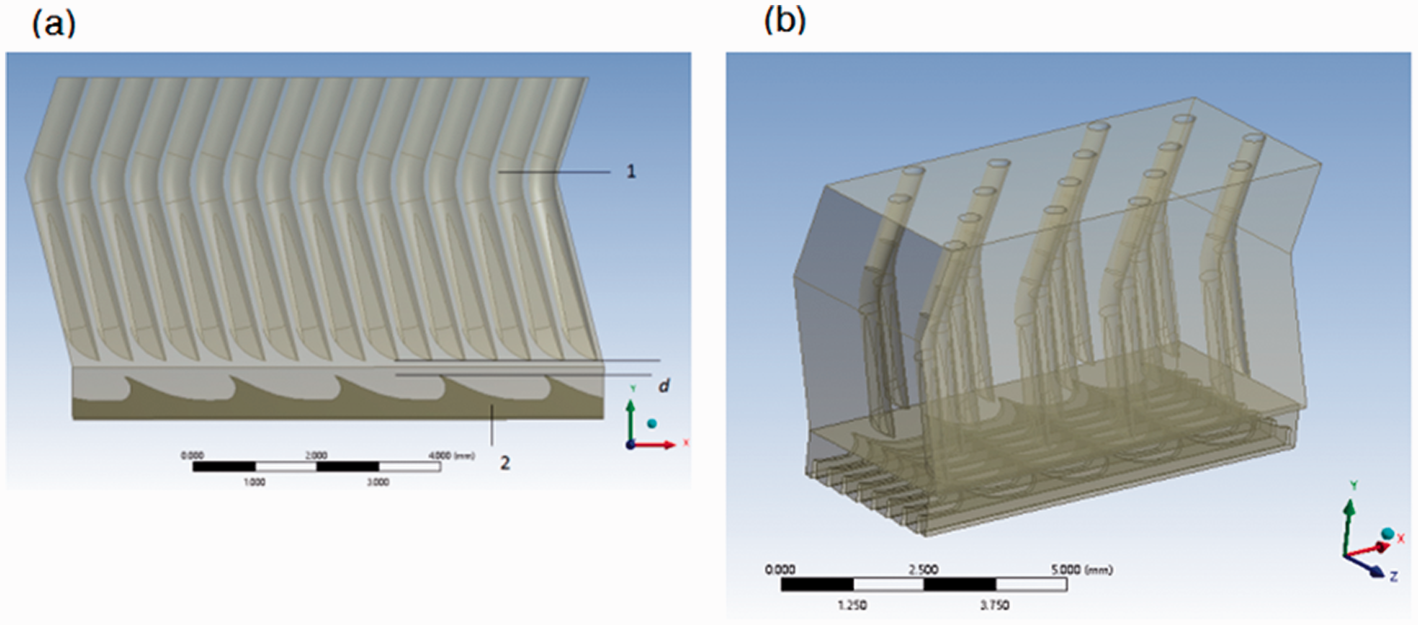
Three-dimensional structure of the simulation fluid domain. (a) From the front. 1: flat domain with real needle arrangement; 2: the cylinder wire domain; d: the gauge. (b) An overall view.
During the carding process, the surfaces of MCC would be filled with fibers. The state of airflow surrounded the surfaces, which affected the contact conditions, should be studied carefully. As a result, the surfaces of MCC meshed with an inflation of 10 layers with the size of approximately 0.01 mm (Figure 4). With the calculation of Y+ in the following simulation, the mesh size was small enough to study the surface according to the theory. Another mesh adjustment area was near the domain interface to converge the simulation when the Shear Stress Transport (SST) turbulence model was applied instead of the k-ε model in other studies. 14
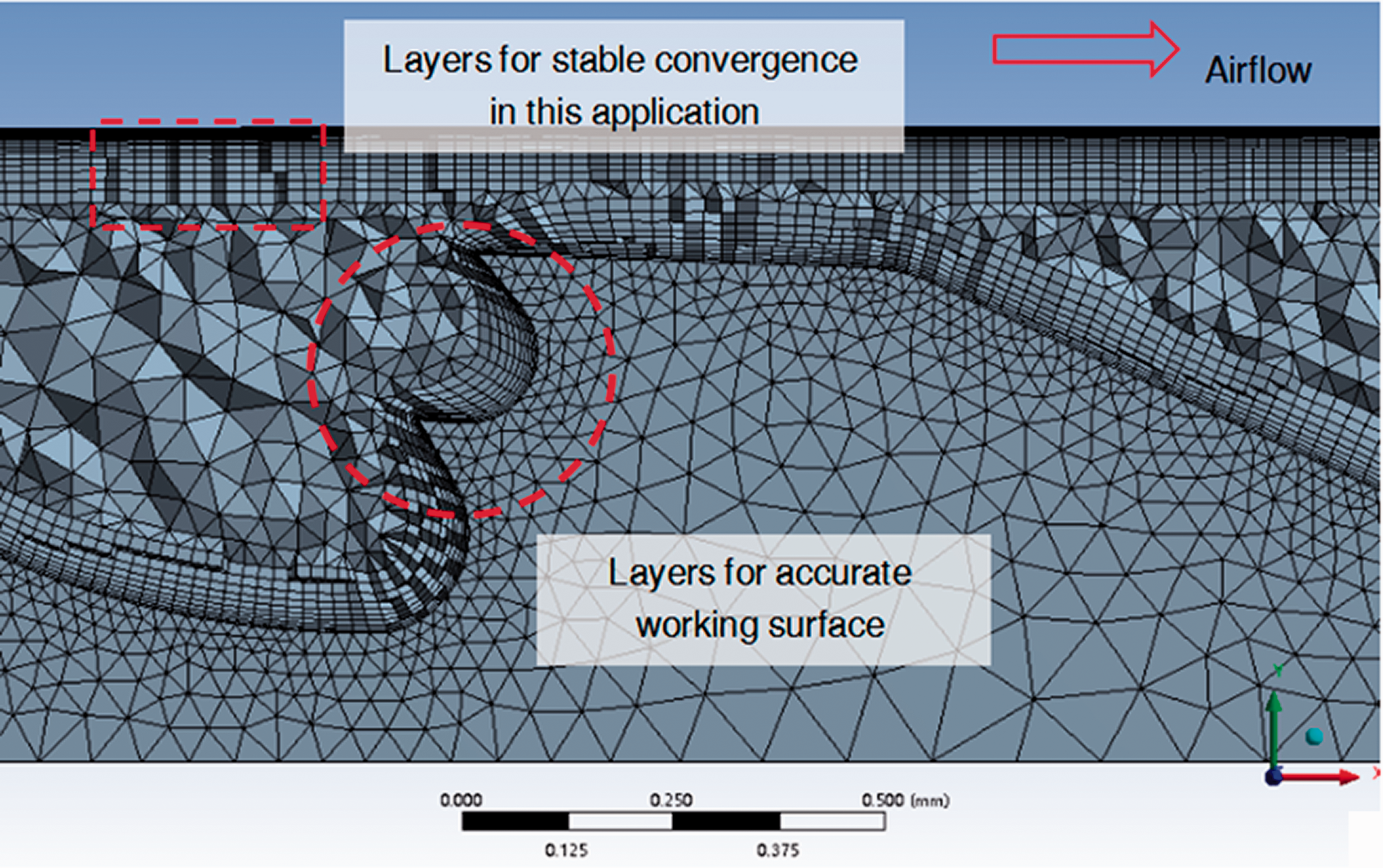
Unstructured mesh with 10 layers on the cylinder teeth surface.
The geometric model and meshing method were different from others’ simulations 14 for different purposes, while the boundary condition settings were the same (Figure 5). The inlet and outlet were both set as velocity boundaries with 0 m/s to meet the real condition in a carding machine. The top domain was stationary despite the fact that the flat top will move in a direction around the main cylinder with a stable velocity. Compared with the high surface speed of the bottom cylinder, this velocity could be ignored. As a result, the top domain was set to be a stationary one. The bottom domain was set with a speed of 500 rpm depending on different applications.
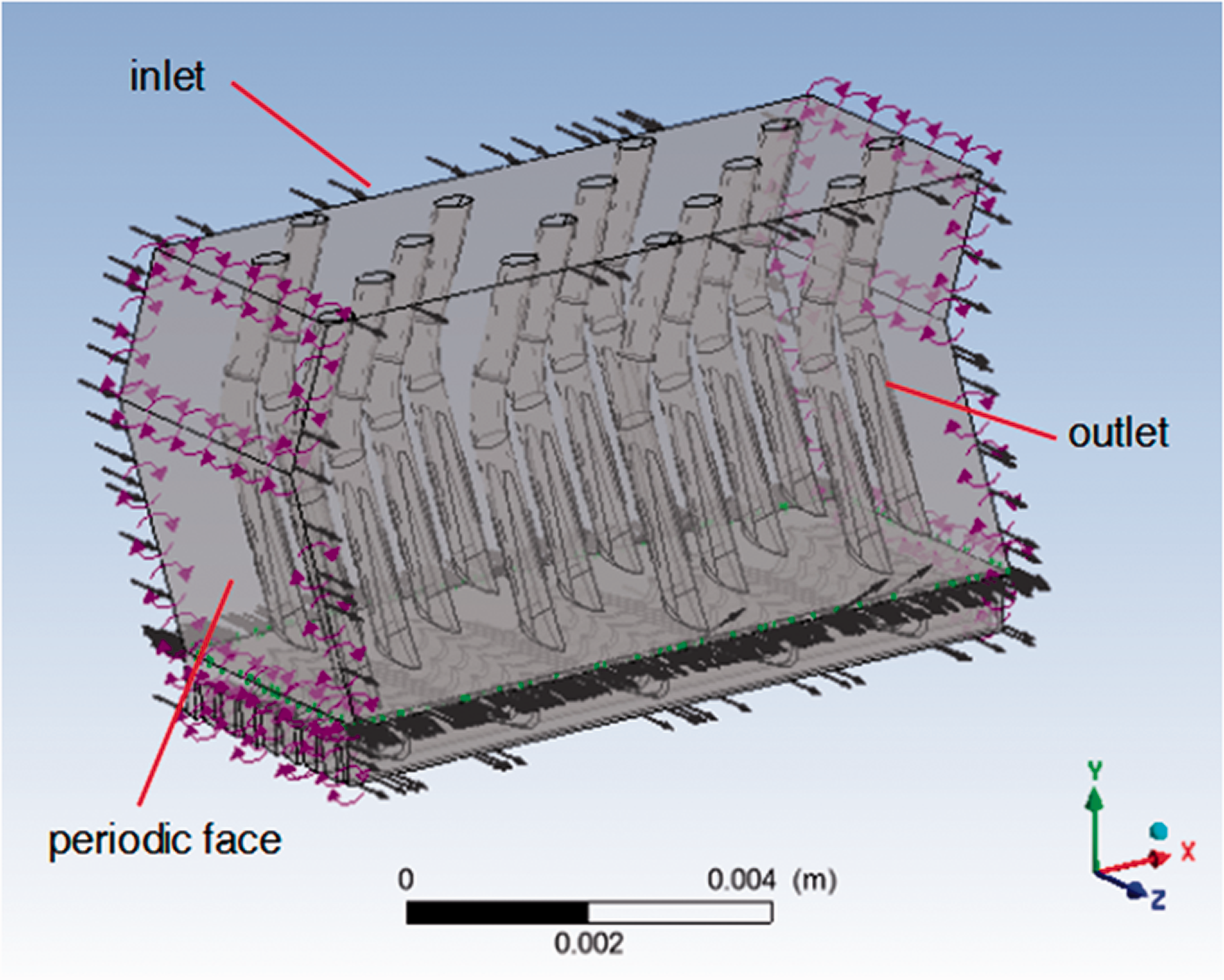
Boundary condition settings of the computational fluid dynamics domain. The black arrows in the domain show the inlet and outlet; the purple circular arrows show the periodic faces; the green arrows show the domain interface. (Color online only.)
The simulation was operated with ANSYS CFX software with its “frozen rotor” model, which is an approximate but stable model to study the airflow between two bodies with relative motivation in industry, especially for this application involving more than 14 million cells. Perhaps it was not the most accurate simulation method, but it was welcome in the industrial field because of its stability. Without any change of mesh parameters and boundary conditions, the calculation would always converge with the root mean square (RMS) residual value below 1e-4 in less than 100 steps when over 20 types of card clothing were applied.
Structural analysis and improved design
During the development of carding clothing in the decades since the 1960s, the tooth depth of the cylinder card clothing for cotton spinning has been shortened from 1.1 to 0.4 mm, or even 0.3 mm, to improve carding efficiency. 1 As a classical principle, the reason for this change was regarded as the greater possibility that fibers will be caught by flat-top needles with the mechanical hold of the card clothing with lower tooth depth. 1 However, the in-depth mechanism was not clear. The airflow may be one of the reasons. If the changes were carefully studied, a new type of carding clothing without shortening the teeth depth but changing the airflow distribution could be invented. This will be of great help because of the avoidance of producing the card clothing with tooth depth less than 0.2 mm, which may result in many manufacturing problems.
In this section, in order to study the changes in airflow when the tooth depth was changed, four types of cylinder tooth profiles were applied. A conventional type that is widely used in carding for cotton with a total height of 2 mm, tooth depth of 0.4 mm, and PPSI of 960 was applied to study the airflow when the gauge was set at 0.24 mm. A virtual type of card clothing developed from the conventional type with a tooth depth of 0.2 or 0.3 mm was applied to explain the improvement in carding quality when the tooth depth decreased. With the conclusions from the former three types, a brand-new structure of cylinder teeth was invented. The new tooth would be simulated as well to predict its performance before it was applied in a carding machine. The cross-sections of the four types are shown in Figure 6. The developed structure can be regarded as an attachment of a smaller tooth to the teeth surface near the larger tooth of a conventional card clothing, forming a repeat unit with double teeth. Thus, the new type of card clothing was named “double teeth” due to its special structural features.
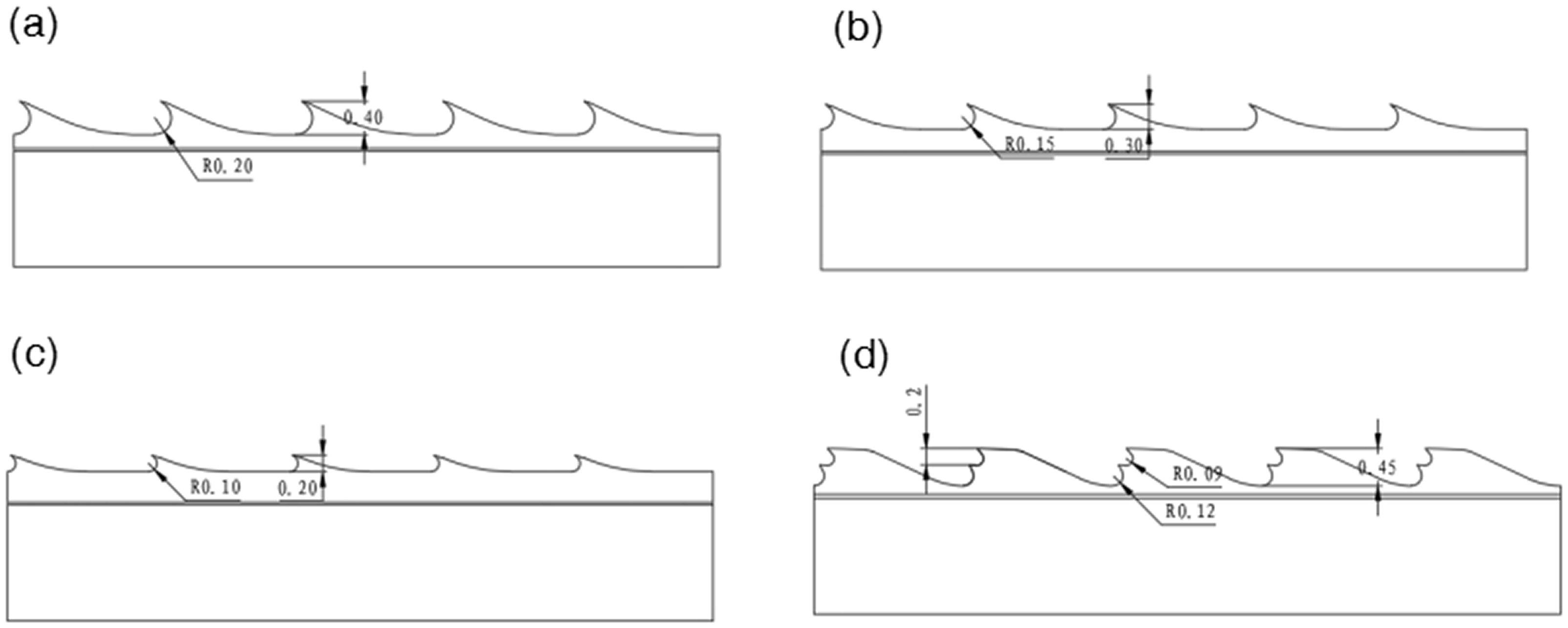
Sections of four different types of card clothing: (a) conventional card clothing with a tooth depth of 0.4 mm; (b) a virtual type of card clothing with a tooth depth of 0.3 mm; (c) a virtual type of card clothing with a tooth depth of 0.2 mm; (d) the new developed “double teeth” generation with a relative deeper tooth depth.
Experiments in spinning mills
To estimate the carding efficiency, several types of double teeth card clothing were developed for different kinds of fibers. This was a necessary step because of the complexity of the carding process. The simulation results always give an optimizing direction, but they cannot solve the carding problems individually at present. The types of fibers and their carding parameters are shown in Table 1. All of these experiments were carried out with the corresponding conventional types as the control groups. The carding performance was then tested by Uster AFIS and Premier aQura to compare the difference between different types of applied card clothing.
Experimental results of the double teeth card clothing in several spinning mills
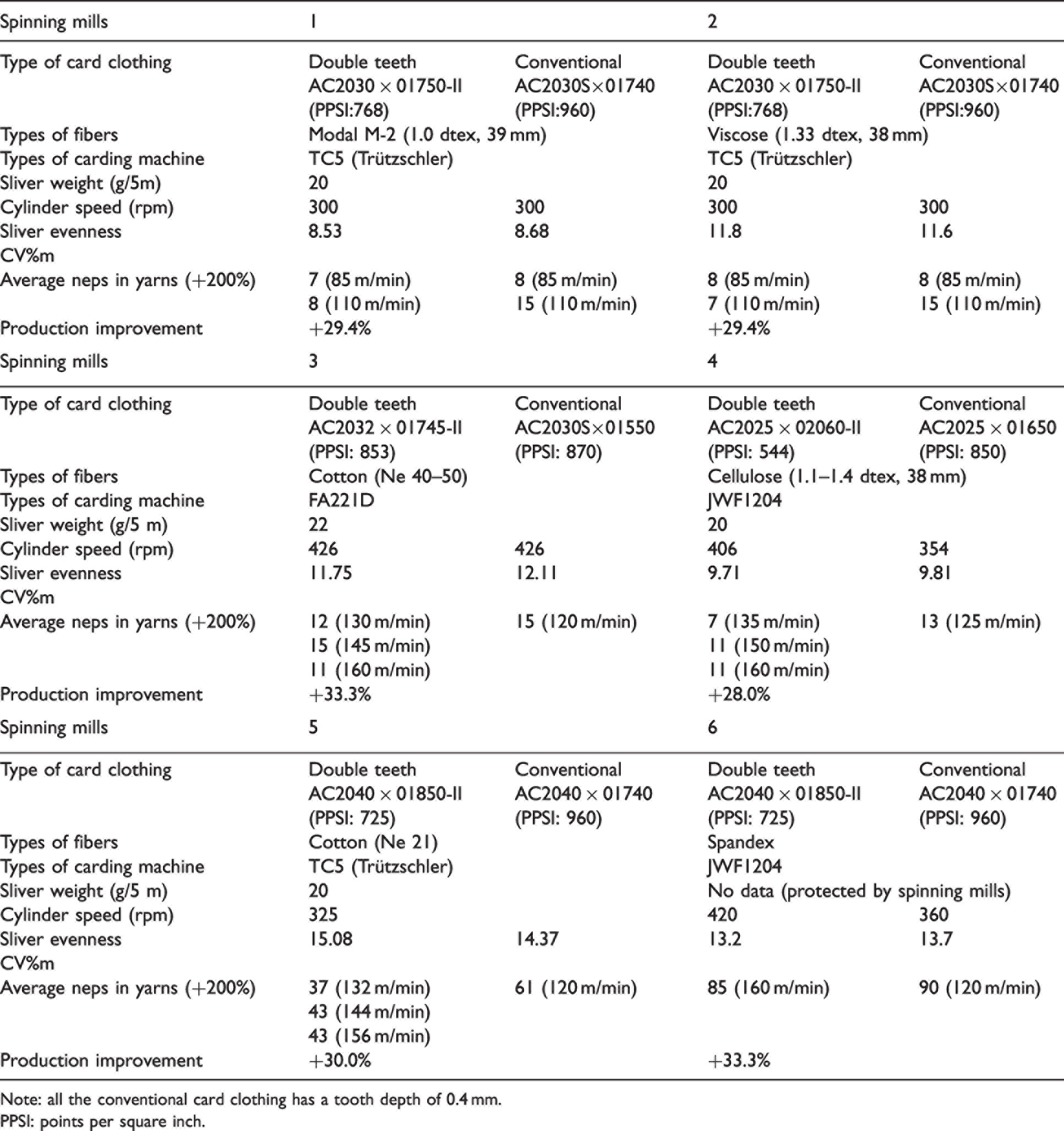
Note: all the conventional card clothing has a tooth depth of 0.4 mm.
PPSI: points per square inch.
The main reason to develop the double teeth card clothing depended on the drawbacks of the low stability of manufacturing the conventional ones with teeth depth of less than 0.2 mm. To estimate the stability of heating treatment during the manufacturing process, three types of different structures, namely the double teeth, conventional card clothing with a tooth depth of 0.4 mm, and a control group with a teeth depth of 0.2 mm, were produced at a length of about 8500 m, which was the amount for a single carding machine. These three types of card clothing were made of the same roll of annealing steel ribbons with the equivalent process. The steel was micro-alloyed high-carbon steel containing about 0.8% carbon and several elements, including tungsten and vanadium, with a austenite transformation temperature of about 850°C when rapidly heated with a high-speed flame with a temperature over 1800°C in less than 0.2 s. The online heat treatment parameters were slightly different because of the different teeth tip volume of these card clothing. Fifty samples were taken from the cylinder uniformly with a length of about 20 cm. The hardness of the teeth tips was measured with a micro-hardness tester after mounting and polishing. Data were then collected and simply analyzed to compare the difference in stability of these three types of card clothing.
Results, analysis, and discussion
The first step was to find what happened to the airflow when the depth was shortened. Figure 7 shows the airflow velocity distribution in the teeth with different tooth depths, taking the cylinder surface as the reference frame. The velocity distribution had the same features as that in the experiments carried out by Juzo Hosokawa and Akira Horikawa in the 1970s with a set of laboratory equipment. 17 The velocity kept decreasing from the teeth top to the teeth bottom in every type, but the region areas of airflow with high velocity where fibers could be driven by airflow were different. The distance from the top of the teeth to where the velocity was 5 m/s in the card clothing with its tooth depth of 0.2 mm was smaller than that of other types. As the main features of the cylinder surface, the teeth influenced the total velocity distribution in all the domains of the cylinder, including those gaps between the teeth. Figure 8 shows a comparison of the airflow distribution between the card clothing with different teeth depths. The lower the teeth depth was, the closer the velocity of the iso-surfaces were to the flat top.
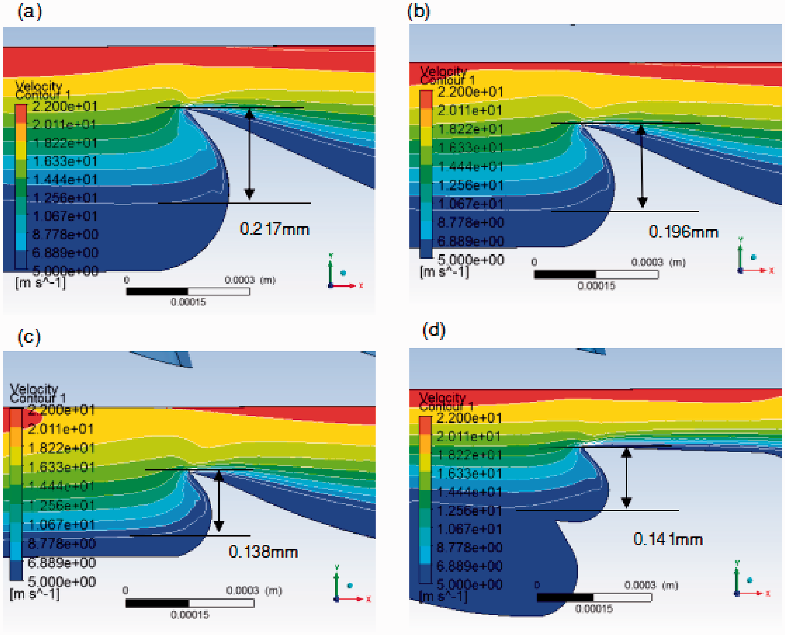
The velocity (taking the cylinder surface as the reference frame) of airflow distribution around the teeth: (a) conventional teeth with a tooth depth of the standard 0.4 mm; (b) modification with a tooth depth of 0.3 mm; (c) modification with a tooth depth of 0.2 mm; (d) the double teeth.
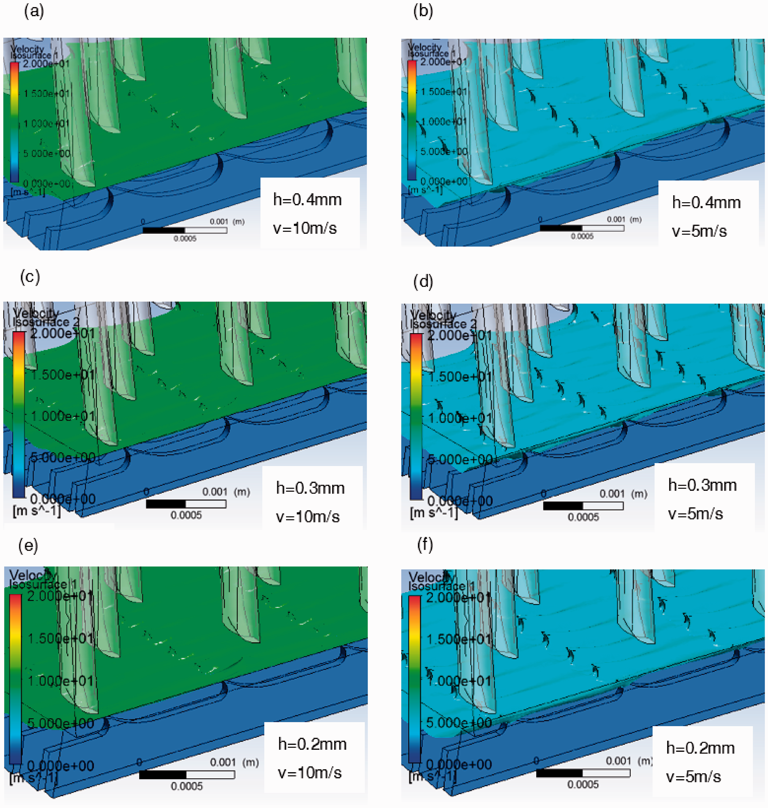
Velocity iso-surfaces of different applications: (a) h = 0.4 mm, v = 10 m/s; (b) h = 0.4 mm, v = 5 m/s; (c) h = 0.3 mm, v = 10 m/s; (d) h = 0.3 mm, v = 5 m/s; (e) h = 0.2 mm, v = 10 m/s; (f) h = 0.2 mm, v = 5 m/s.
This was not in conflict with the conclusions from the former article 14 because of the difference in reference frames. When the surface of the cylinder was taken as the reference frame, the air velocity could reflect the fiber's motivation relative to the cylinder teeth. That the reference velocity is other than absolute velocity made sense because of the targets of studying the behavior of the fiber on the cylinder, not the air generation source.
These results showed an airflow concentration on the teeth tips when the tooth depth was shortened. When a card clothing with a smaller tooth depth was applied, the airflow tended to get through the teeth at the tip area, where was closer to the flat top instead of the bottom. This phenomenon could be an explanation by a historic evolution of shortened teeth depth with an assumption from the angle of airflow.
The assumption was that fibers would like to transfer through the cylinder teeth surface at the high-velocity areas because of the large throughput capacity by volume at these regions in the same time interval. When this assumption had been proved, the fibers would have got through the teeth more likely at the teeth tips. In this way, fibers seemed to gather at the top tip even though the fibers were distributed whole at the teeth. The mass flow of air was calculated to study the airflow distribution in detail. The cross-section of the air channel between every two types of card clothing was separated into two parts. The top part was the region of the tooth tip to 0.1 mm below itself, which represented the airflow around the tooth tips, while the left represented the bottom airflow. The ratio of mass flow in the top region and the total channel was chosen to be a feature to quantify the gathering degree of airflow in the teeth tip region. Figure 9 shows the increase in the gathering degree when the tooth depth was shortened. The ratio in the card clothing of its tooth depth of 0.2 mm had increased by 22% compared to the 0.4 mm one.
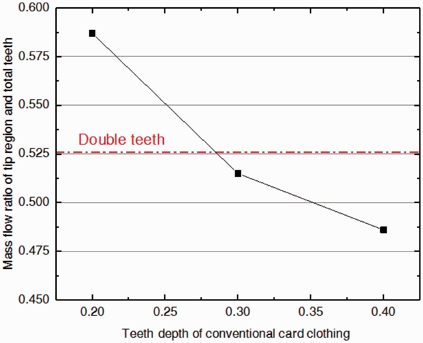
The airflow ratio in the teeth tips increased by the reduction of the teeth depth. The double teeth are shown with a red line. (Color online only.)
Fibers are more likely to be caught by the needles at their tails when they were transferred along with the cylinder teeth in the region closer to the flat needles, so the fibers were separated from the tufts more effectively and the carding efficiency was improved. This was a classic theory to explain the fact that narrow space settings between the cylinder and the flat top do help the quality of carding. In this article, the basic theory was the same. The difference was just the method to make the distance much closer. In this article, the “tool” was airflow. A short teeth depth produced more airflow at its teeth tip, increasing the ratio of fibers passing through the cylinder teeth at the teeth tips, where were closer to the flat needles. As a result, more fibers underwent adequate carding, increasing the carding efficiency. The double teeth card clothing was created not by the reduction of tooth depth directly but by the in-depth mechanism behind this classical principle, which could be the airflow distribution.
The double teeth card clothing was invented with the expectation that the smaller teeth attached to the working surface of the main teeth could affect the airflow and guide it the same as those teeth with a depth of 0.2 mm. The comparison was shown in Figures 7(c) and (d), where the high-velocity areas were nearly the same. A comparison of the iso-surfaces is shown in Figure 10.
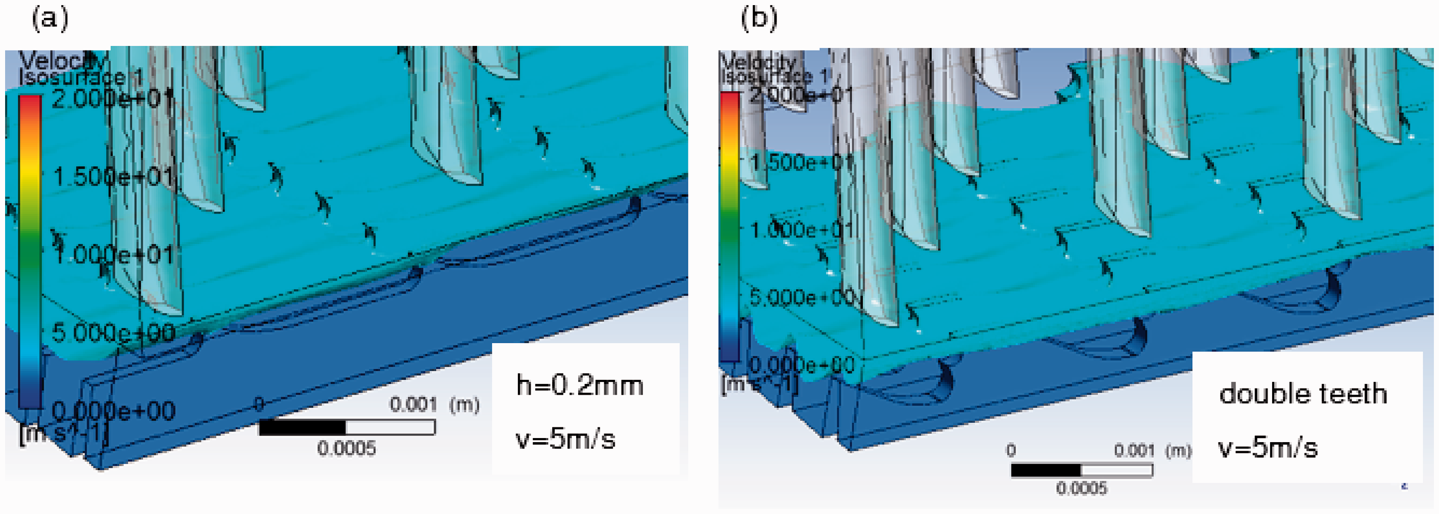
Velocity iso-surfaces of different tooth profiles: (a) conventional with a tooth depth of 5 m/s; (b) double teeth.
The mass flow ratio of air around the tooth tip and the total teeth was 0.526, which was larger than the 0.3 mm used conventionally. This meant that the double teeth could show an improvement compared to the conventional ones, at least better than the teeth depth of 0.3 mm. It seemed that the airflow was “held up” by the smaller teeth at the bottom, and the air below the teeth seemed to be static compared to other areas.
Another issue that should be taken into account was the working surface pressure generated by the airflow. This physical result could be an approximate index to distinguish the “holding ability” of card clothing in different applications. The hypothesis was simple that fibers were “pressed” on the working surface when airflow flowed past the surface of the card clothing teeth. The pressure between the fibers and the work surface may have a positive relation with the pressure generated by the airflow, which could be calculated by CFD. As the pressure increases, the friction between fibers and work surface increases according to the most classical friction equation. As a result, the “holding ability” of the teeth has increased. By the classical design principles of the conventional card clothing, the “holding ability” of teeth increases when the tooth depth and working angle increases, or the arc in the front of the working face decreases. 1 The results from the simulation showed the same tendency as above when these design parameters were changed within classical dimensions (teeth depth 0.4–0.8 mm, working angle 10–40°, arc 0.12–0.25 mm), which meant the rationality of connecting the pressure generated by the airflow and the “holding ability.” Once the relationship was established, the “holding ability” of the newly design card clothing could be predicted more exactly through calculation than in the classical way directed by engineering practices. However, the pressure played a role related to the “holding ability,” but it was not the only one. This meant that the same calculated pressure might result in different “holding abilities,” especially for multi-design parameters that are changed at the same time. As a result, the experiments in the spinning mills were necessary.
Figure 11 shows the average pressure of the working surfaces of the conventional and the double teeth card clothing with different PPSI. To eliminate errors as many as possible, the sampling teeth were in the same position in the cylinder domains. It could be concluded from the figure that the double teeth card clothing with PPSI 768 has a similar performance to the conventional one with a tooth depth of 0.4 mm with a slight increase in the cylinder speed. This was welcome, because it may increase the production because of the increase of the speed of the cylinder. Meanwhile, the double teeth with a higher PPSI of 960 could harm the fibers because of the possibility of fiber breakage when the “holding ability” became too strong. These assumptions will be verified in the following experiments.
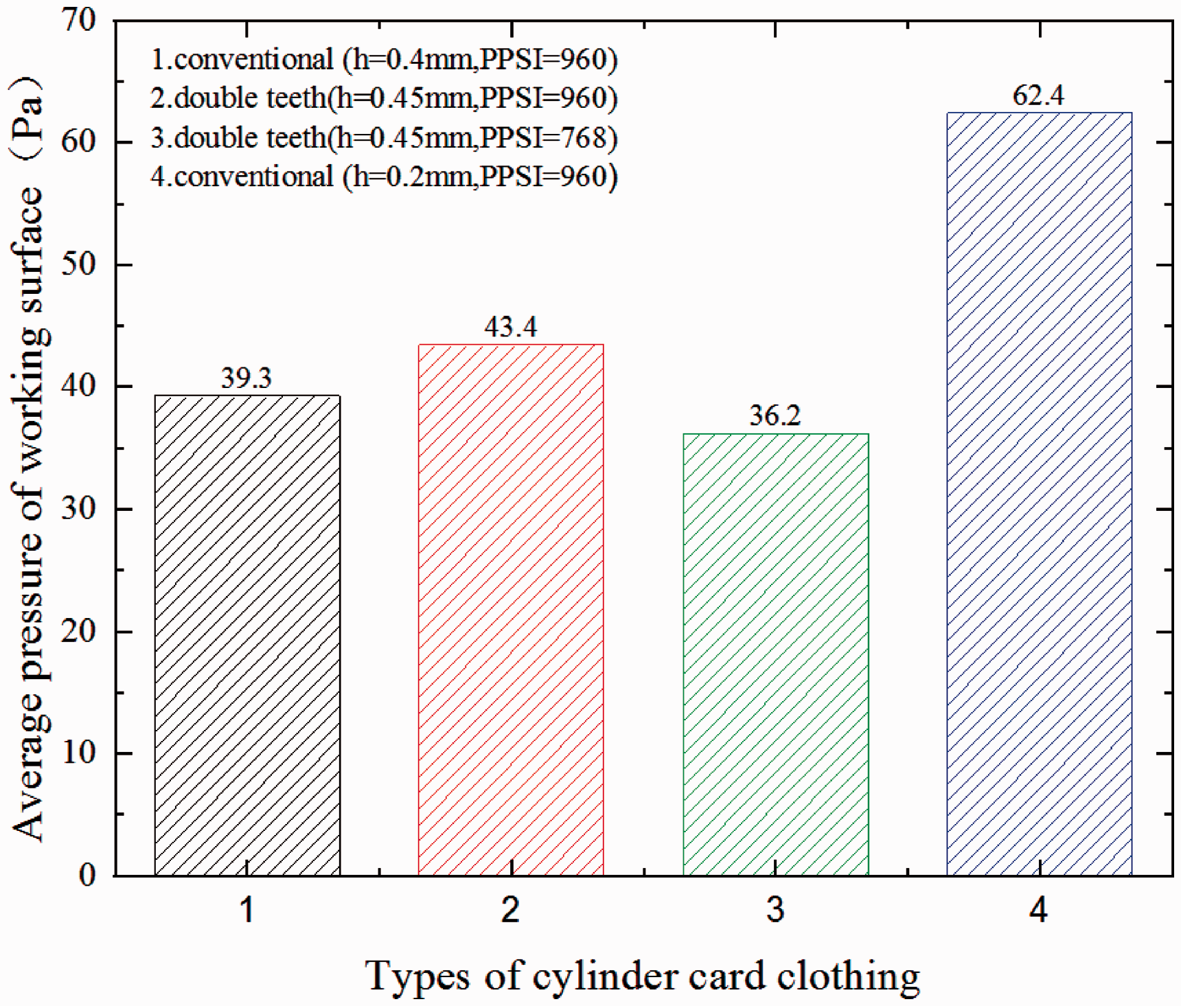
Average pressure generated by the airflow of the working faces for different designs of card clothing. The character “h” in the figure represents the tooth depth of the card clothing. PPSI: points per square inch.
Experiments were carried out in several spinning mills to confirm this opinion, as shown in Table 1. It could be concluded from the table that the production could be improved by about 30% for different fibers, including cotton, modal, viscose, cellulose, and spandex, with the same quality as the conventional card clothing (Figure 12). The double teeth in Table 2 and Figure 13 had a reduction in their PPSI for the elimination of too much breakage of fibers. The experiments were carried out with different doffer speeds, and it was found that with the same PPSI, double teeth would increase the breakage percentage of fibers compared to the conventional one. Different doffer speeds showed that the breakage was produced by the carding clothing itself other than the changes in the fiber shift in the cylinder–doffer interface. This phenomenon suggested that the smaller teeth might also take part in the carding process, playing a more important role than just guiding the airflow. The drawbacks were then eliminated by the reduction of PPSI by 15–30%, depending on the different applications. However, this modification was not dependent on specific applications.
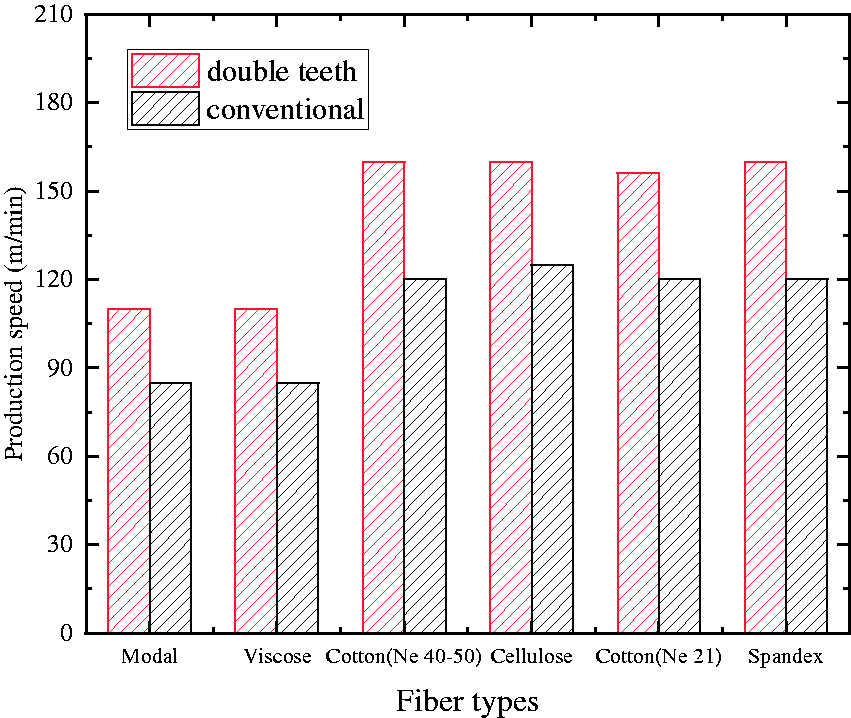
Improvements in production speed by double teeth for varied types of fibers without a decrease in the yarn quality.
The breakage improvement when the double teeth with the same points per square inch (960) as the conventional method were applied
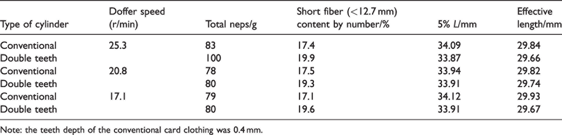
Note: the teeth depth of the conventional card clothing was 0.4 mm.
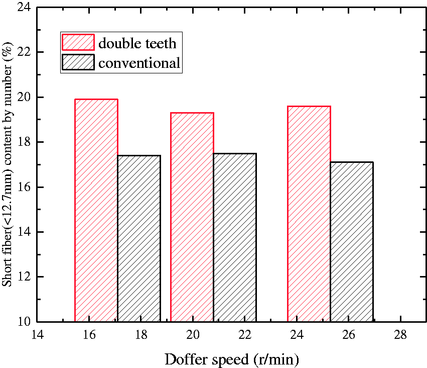
Higher breakage of fibers by double teeth than conventional card clothing with the same points per square inch (PPSI), which could be reduced to a normal level with a slight decrease of PPSI.
These experiments took the technical teams about 6 years to complete because of the complexity of the textile industry. It was difficult to find a spinning mill equipped with advanced fiber detection equipment that would like to do the experiments on its online carding machine with the risk of reduction in quality or production capacity. To improve the reliability of the results, the experiments must be carried out in spinning mills rather than just in the laboratory because there are too many drawbacks, including limited fiber types, operating hours, and process parameters. The results proved the right design direction of carding clothing concerning the airflow around the teeth.
There was a question as to why the double teeth card clothing could be manufactured stably but card clothing with teeth with a tooth depth of 0.2 mm could not. The first reason was that the matching accuracy of punching dies got worse when smaller dies were used. It is a fact that no carding clothing manufacturer could offer carding clothing with a tooth depth of less than 0.25 mm as yet without any other concerns, including materials and heat treatment. The second reason was t the quenching limitation. To ensure the wear resistance of the tips, the tips always have a hardness of more than 800 Hv. In contrast, the bottom of the teeth were an arc or a line that should have a hardness of less than 300 Hv to avoid fracture when drawn up on the rollers. The variation of the hardness alone in the tooth depth would be more intensive if a short tooth depth was applied. This would make it a challenge to control the heating period before quenching, when much smaller teeth were applied. The advantage of the double teeth card clothing avoided both problems with a clever design. As a result, the production could be manufactured in a common production line with few changes in the process parameters. The tests of hardness shown in Figure 14 confirmed the heat treatment drawbacks mentioned above where the double teeth showed nearly the same stability as the conventional ones with a tooth depth of 0.4 mm, while those in the carding clothing with a tooth depth of 0.2 mm seemed to be unstable. Significantly, the high standard deviation of hardness resulted from not only the heat treatment process containing fire temperature, but also structure changes between the teeth. The teeth were easier to control at the same size. The larger ones underwent insufficient heating, resulting in a decrease in the tip hardness, while the smaller ones were the opposite. To avoid the overheating of smaller teeth, the temperature of the heating fire was reduced. This was why the average hardness of the tips decreased, as shown in Figure 14. Despite the decrease in the temperature of the fire, the hardness of the bottom still reached a higher hardness than the others, which increased the risk of fracture when drawn up. The results confirmed the drawbacks of the traditional method to develop new card clothing by shortening the tooth depth.
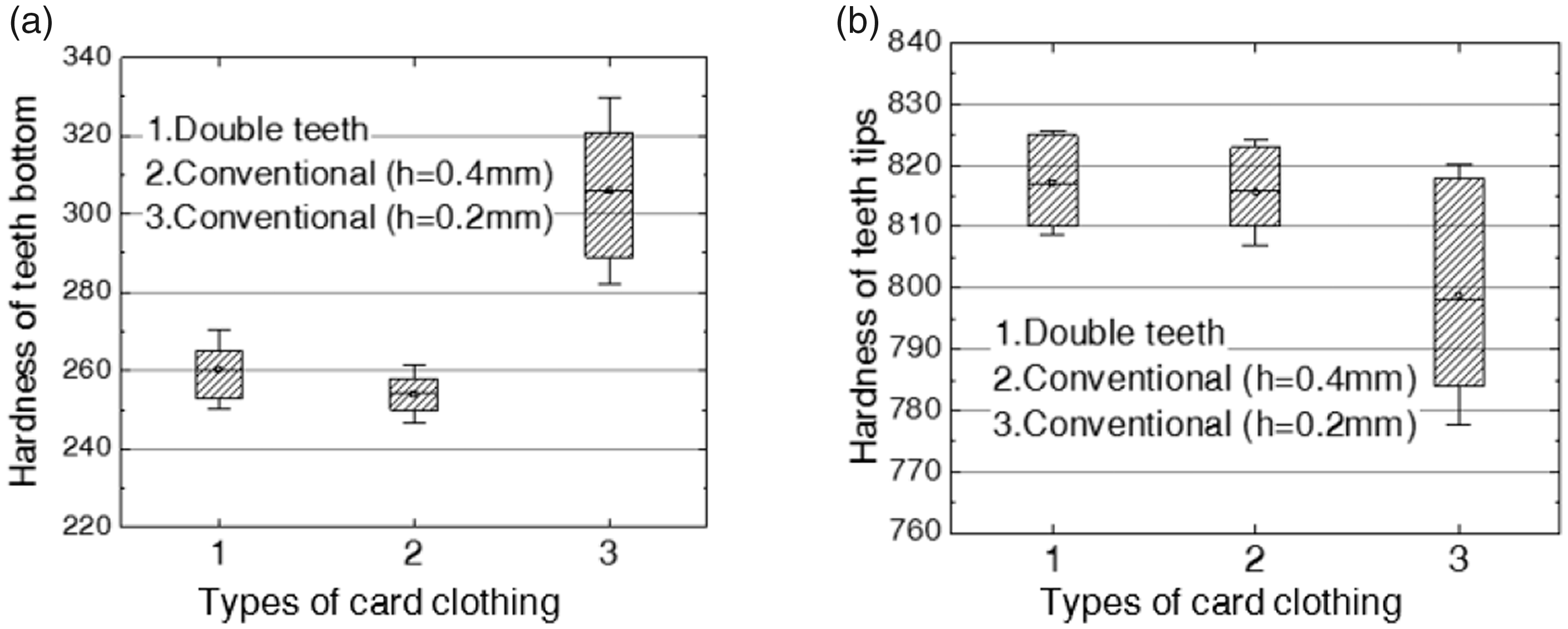
Comparison of the hardness stability of three types of card clothing during manufacturing: (a) standard deviation of the hardness of the teeth bottom; (b) standard deviation of the hardness of teeth tips. The character “h” in the figure represents the tooth depth of the card clothing.
Another advantage of the double teeth could be the protection of fibers because they did not increase the pressure of the working face (Figure 11). Significantly, the numerical value of the pressure was just a direction guider for the optimization of card clothing instead of a quantitative description of carding performance, meaning that the decreasing or increasing level in quantity made no sense. The optimization of card clothing cannot be carried out without experiments in real spinning mills or test platforms established in spinning labs.
Due to the excellent performance of the double teeth card clothing, it was introduced to one of the largest textile enterprises producing spandex on a large scale and applied on over 1000 carding machines for 4 years as of now, and it had an improvement in production of 20% as a result. By tracking the performance in the spinning mills, wear-resistant problems were observed. According to the collected information, the wear of card clothing seemed to be influenced by its structure. There is almost no literature discussing this topic. Only a patent 18 applied by Ralph A Graf considered the structure design of the carding clothing to be a method to improve the wear resistance instead of applying expensive alloyed steels. Recent research related to the design of the worker's teeth for nonwovens also showed wear resistance improvement when a new structure was applied. 19 A simple experiment with some parameter variation of the double teeth card clothing was carried out by our team in the spinning mill, which supported the point of view that the life span of the double teeth card clothing increased by at least 50% on average without changing the material (Figure 15). Despite the possibility that the wear resistance could be influenced by the fiber distribution on a tooth by its structure, the in-depth relationship between the structure and wear resistance remains a mystery; this needs further analysis and practical testing.
The different wear resistance of different modifications of double teeth with the same manufacturing process and material. The pictures were captured online by a portable optical microscope on two carding machines installed in the same condition. (a) A modified double teeth card clothing with a slight groove wear on the front surface of the teeth after dealing with 70t fibers. (b) Another one with a different structure made from the same material showed no obvious wear after dealing with 125t fibers. The former had an obvious wear groove caused by fewer fibers, while the latter had nearly no wear.
The wear resistance problems of double teeth should be solved because the shorter life span could increase the money spent on card clothing for spinning mills, despite the advantage that this new invention resulted in little increase in cost in its manufacturing.
There were a great number of selections for the conventional carding clothing to be modified, for example, adding a smooth hump instead of the teeth to avoid punching problems. 20 However, each newly developed card clothing in this way should be tested carefully and patiently in spinning mills at a reliable scale to avoid the possibilities of great drawbacks in the wear resistance, although this will take several years.
Conclusions
In this article we attempted to develop an improved type of MCC with the help of airflow properties around the carding teeth to achieve high carding efficiency. CFD was chosen as a very effective analytic method to study the intensive airflow between the carding elements. Through analysis and engineering practice, the following conclusions could be drawn.
With the observation of conventional card clothing with different tooth depth and classic design principles, the conclusion that there was carding efficiency improvement in card clothing with a lower tooth depth may be related to the more concentrated air velocity at the tooth tips, which may result in greater probability that fibers could be caught by flat-top needles. Thus, an improved type of card clothing that accounted for this conclusion with two teeth in one section was developed. The manufacturing of double teeth showed the same stability as the conventional ones, which the carding clothing designed depending on the traditional principles could not achieve. The analysis of pressure on the working surface of the teeth would be helpful in the prevention of fiber breakage and the qualitative forecasting of carding performance.
The latter experiments carried out in spinning mills showed a considerable improvement in the carding performance with different modifications for different types of fibers. The industrial-scale applications showed an improvement in production by 30% with no decrease in quality. The results showed success in the developing of a new generation of card clothing, which also meant that the method by the adjustment of airflow around teeth through CFD could be a fine choice when engineers want to develop a card clothing to solve carding problems. The experiments in spinning mills need further analysis, improvement, and optimization because of the possibilities of drawbacks in the wear resistance of newly designed card clothing.
Footnotes
Declaration of conflicting interests
The author(s) declared no potential conflicts of interest with respect to the research, authorship, and/or publication of this article.
Funding
The author(s) disclosed receipt of the following financial support for the research, authorship, and/or publication of this article: This work was supported by the National Natural Science Foundation of China (Grant No. 51275414) and the Research Fund of the State Key Laboratory of Solidification Processing (NWPU), China (Grant No.130-QP-2015).