
Abstract
Polylactic acid (PLA) microfibrous membranes, having high comfort and wearability features, have attracted considerable research interest for applications involving skin contactors. However, the poor softness and low strength of these membranes are the major challenges that prevent their large-scale fabrication and application. Herein, an advanced strategy for preparing a soft, strong, and breathable polylactic acid/polyethylene glycol (PLA/PEG) microfibrous membrane using an in situ drafting-assisted melt-blowing process has been developed. The introduction of PEG significantly improved the crystallization and plasticization of the PLA chain molecules, thus promoting the perfect crystallinity of the PLA phase. Benefiting from the synergy of the PEG and the drafting process, the prepared PLA/PEG microfibrous membranes exhibited a fluffy structure wherein the air permeability increased to 142.5 mm/s with the increase in DCD to 37 cm. Meanwhile, the PLA/PEG microfibrous membranes exhibit optimized anisotropic softness performance: a smaller maximum resistance of 0.13 N in the machine direction and a larger maximum resistance of 1.8 N in the cross direction were obtained in comparison with conventional membranes. This suggests the tremendous potential for using the fabricated membranes in flexible, breathable, and wearable skin contactors.
The investigation of polylactic acid (PLA) microfibrous membranes has been a hot research topic for sustainable applications in skin contactors such as wound treatment,1–4 personal protective equipment, 5 and smart wearable products. 6 This is precisely on account of the fascinating advantages of PLA microfibrous membranes, such as easy processability, biodegradability, and a high surface-area-to-volume ratio. However, commercial PLA microfibrous membranes usually suffer from certain shortcomings (i.e. poor softness and low strength) caused by their inherent brittleness and a disordered microfibrous structure.7,8 Nevertheless, with the increasing number of aging individuals among human populations and general lifestyle changes in human society, 9 the demand for skin contactors fabricated from PLA microfibrous membranes has surged in the past few decades. Therefore, improving the softness performance and mechanical properties of PLA microfibrous membranes is of critical and urgent interest.
Recently, significant attempts have been made to develop PLA microfibrous membranes with enhanced strength through improved strategies such as assisted drafting during the preparation process10–12 and blending with reinforcing agents.13,14 The assisted drafting method feasibly transforms membranes with poor fiber alignment into a highly oriented structure by driven combining stretching, leading to improved mechanical properties.15–17 More importantly, previous research has demonstrated that the assisted drafting process is also effective for improving the alignment of fibers and making the fibers thinner. Liu et al. 18 reported an electrospinning system consisting of a yarn-forming unit and a hot-stretching unit to fabricate silk fibroin/PLA fibrous yarns. It was found that the fiber alignment and mechanical properties were significantly improved as a result of the hot-stretching process. Hsu et al. 19 reported hot-stretching electrospun fibers, prepared at temperatures higher than the glass transition temperatures of the polymers. The strategy resulted in improved alignment and a reduction in fiber diameters. However, many obstacles are still encountered as the target size of fibers decreases, in particular, issues related to increasing the softness and breathability of membranes for skin contactor applications. Thus, blending modification has been widely applied to overcome these obstacles. The most popular commercial plasticizer used to increase the flexibility of PLA is polyethylene glycol (PEG), which has a low molecular weight and good skin compatibility.7,20 It has been reported in previous literature10,21 that PEG can be successfully employed to plasticize PLA. PLA/PEG blends show a higher elongation and a lower modulus. Various studies have proved that PEG molecules can be well dispersed in the PLA chain molecule matrix during the physical melt-blending process, 22 resulting in better mechanical properties.
Significant attempts have been made in the past to develop PLA microfibrous membranes through strategies such as electrospinning,23–26 solution blow spinning, 27 centrifugal spinning, 28 and melt blowing. 29 Among these strategies, the melt-blowing process is one of the most popular methods for commercially manufacturing PLA microfibrous membranes, since it furnishes membranes with satisfactory properties.30,31 Meanwhile, melt-blowing processes are environmentally friendly, high throughput, and low cost. However, although tremendous effort has been devoted toward enhancing the softness and strength of PLA microfibrous membranes, only limited work has been reported on the large-scale fabrication of sustainable soft, strong, and breathable PLA microfibrous membranes, for skin contactor applications through a combination of assisted drafting and blending strategies in the melt-blowing process.
In this work, highly aligned and porous PLA/PEG microfibrous membranes were prepared by an in situ drafting-assisted melt-blowing process. The structural properties of the surface as well as cross-sectional morphologies, fiber diameters, and thicknesses of the samples prepared with various PEG mass ratios at different die-to-collector distances (DCDs) were studied in detail. The thermal properties of the PLA/PEG blended polymers were investigated via differential scanning calorimetry (DSC) and thermogravimetric analysis (TGA). Furthermore, the softness, air permeability, and mechanical properties of the prepared membranes were investigated to determine their suitability for sustainable industrial applications such as in the development of skin contactors.
Materials and methods
Materials
PLA chips with molecular weights ranging from 30,000 to 35,000 were kindly supplied by CGN Juner New Materials Co., Ltd. A PLA chip had a melting flow index of 21 g/10 min at 210°C and a density of 1.24 g/cm3. Prior to use in experiments, the PLA chips were dried for approximately 10 h at 80°C. PEG pellets with molecular weights of approximately 6000 were purchased from Jiangsu Haian Petrochemical Plant. The density of a PEG pellet was 1.12 g/cm3.
Membrane preparation
As schematically depicted in Figure 1, PLA/PEG microfibrous membranes with an ordered fluffy alignment structure were prepared by an in situ drafting-assisted melt-blowing process in two steps. First, PLA/PEG blended chips were prefabricated by a melting/blending/stirring process. The PEG pellets were added to a metal beaker and allowed to melt at 80°C. A few PLA chips were blended with the PEG melt, which was cooled to room temperature, forming coated PLA chips wrapped by PEG. The coated chips were stirred with PLA chips, resulting in the formation of PLA/PEG blended chips containing PEG in mass % equivalent to 0 (pure PLA), 0.5, 1.5, 3, and 5 wt%. Next, the PLA/PEG blended chips were fed into an extruder through a hopper and melted into a blended melt. Under the extrusion of the screw and heating from the heater, PLA became miscible with PEG, and the PEG molecules were incorporated into the PLA chain molecule matrix through physical melt blending. This PLA/PEG blended melt was ejected from the die with a diameter of 0.25 mm and then extruded onto conveyer belt-A with a velocity V1, forming PLA/PEG microfibrous webs. Finally, PLA/PEG microfibrous membranes were transferred onto conveyer belt-B with a velocity V2 and in situ drafted into an aligned microfibrous fluffy membrane. The drafting ratio is defined as the velocity ratio between the velocities of belt-A and belt-B. To investigate the effects of the polymer properties upon membrane morphology, PLA/PEG microfibrous membranes were drafted in situ along the machine direction by applying a drafting ratio of 1.8. The main melt-blowing process parameters (i.e. DCD, air temperature, and drafting ratio) have been summarized in Table S1 within the supporting information. The thickness and porosity of the PLA/PEG microfibrous membranes were controlled by adjusting the DCD.
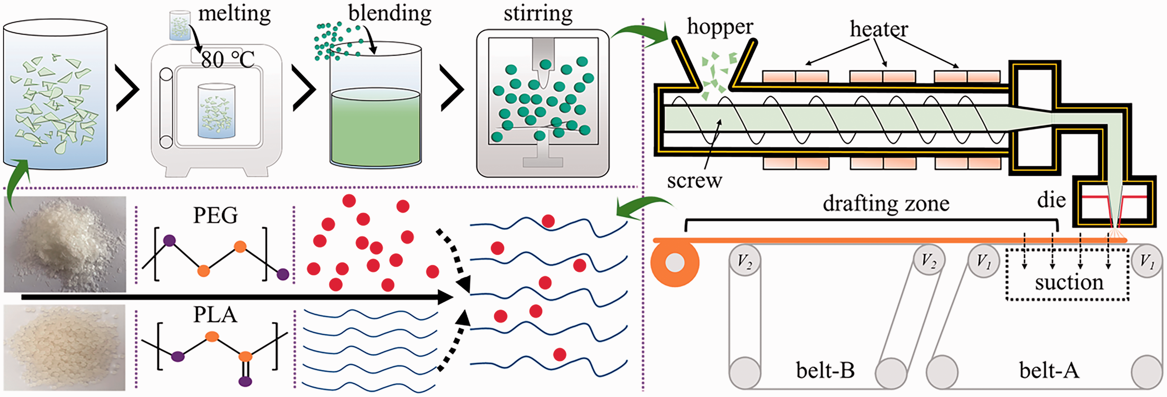
Schematic illustration of the preparation of PLA/PEG microfibrous membranes with a fluffy alignment structure via an in situ drafting-assisted melt-blowing process.
Characterization
The melting behavior and thermal stability of the PLA/PEG blended polymers were evaluated by DSC (Discovery 25, TA Instruments, USA) and TGA (209 F1, Netzsch, Germany), respectively, under a nitrogen atmosphere. DSC testing was performed with a heating rate of 10°C/min in the temperature range of 30–200°C. TGA analysis was performed by heating the samples to 550°C at a heating rate of 20°C/min. The surface and cross-sectional morphologies of the prepared PLA/PEG microfibrous membrane samples were investigated by scanning electron microscopy (SEM) (EVO18, Zeiss, Germany). The obtained SEM images were analyzed by software (OrientationJ, ImageJ plugin, Switzerland) 32 to determine the fiber orientation. The distribution of fiber diameter was evaluated by testing 50 fibers from the surface SEM images. Fourier transform infrared spectrometry (FTIR) (TENSOR 37, Bruker, Germany) was used to analyze the functional group composition of the prepared PLA/PEG microfibrous membranes. X-ray diffraction (XRD) analyses of the prepared PLA/PEG microfibrous membranes with different PEG mass ratios were carried out using a powder X-ray diffractometer (D2 PHASER, Bruker, Germany). The mass per unit area and thickness of the prepared PLA/PEG microfibrous membranes was tested using a digital thickness meter (YG141D, Wenzhou Darong Textile Instrument Co., Ltd, China) and an electronic balance (BK-303G, Dongguan YIXUE Electronics Co., Ltd., China) according to GB/T 24218.1 and GB/T 24218.2, respectively. The porosity of the prepared PLA/PEG microfibrous membranes was calculated by employing Equations S1–S2 in the supporting information. The softness and related properties of the membranes were evaluated by a PhabrOmeter system (Phabr Ometer, Nu Cybertek, Inc., USA) and Handle-O-Meter method testing equipment (homemade equipment) according to AATCC 202-2014 33 and ASTM D 2923-95, 34 respectively. To use the PhabrOmeter system, samples with a circular area of 100 cm2 were placed on a platform with a central nozzle and a continuously moving upper metal rod. The circular sample was subsequently inserted through the nozzle, and the generated resistance force–displacement curve reflected the softness properties. The softness performance of the samples prepared in the machine direction and cross direction was further quantified via homemade equipment based on the Handle-O-Meter method. During testing, each sample was placed on a platform containing a slit with dimensions of 10 × 200 mm in size, and a plate-shaped side head was used to press the sample into the slit. The air permeability of the fluffy alignment structure was investigated by experimental methods as well as numerical calculations. An air permeability tester (YG461E, Wenzhou Darong Textile Instrument, China) was used for air permeability experiments. A virtual model of the corresponding microfibrous alignment fluffy structure was constructed, and air permeability virtual testing was subsequently carried out using software (GeoDict, Math2Market, Kaiserslautern, Germany). The mechanical properties of the membranes (tensile strength and elongation at break) were measured using a mechanical tester (HD026N, Nantong Hongda Experimental Instrument Co., Ltd., China) according to GB/T 24218.3.
Results and discussion
Thermal properties of the PLA/PEG blended polymer
The thermal properties of PLA/PEG blended polymers have a notable influence on the microstructure and performance of prepared membranes using the melt-blowing process. Therefore, the melting behavior and thermal stability of the PLA/PEG blended polymers have been investigated. Figure 2(a) to (c) shows the second heating curves obtained from the DSC analysis of the PLA/PEG blended polymers. Figure 2(a) clearly shows that the glass transition temperature (Tg) and melting temperature (Tm) of neat PLA were 59.63°C and 148.29°C, respectively. This is in agreement with the analysis of the thermal properties of pure PLA carried out by Li et al. 35 Compared with pure PLA, the Tg of the PLA/PEG blended polymer decreased by approximately 6°C when the PEG mass ratio was 5 wt%. This trend indicates the intense plasticizing effect of PEG on PLA. The PLA molecular chain mobility was enhanced because of the binding of PEG molecules to the internal PLA molecules.36,37 Notably, the decline in Tg indicates that the PLA/PEG blended polymer was quite miscible. Figure 2(b) shows that for the neat PLA polymer, a cold crystallization peak appeared near 110.26°C. The cold crystallization peak intensity of the PLA/PEG blended polymer was significantly higher than that of pure PLA. With the increase in PEG mass ratio to 5%, this peak shifted to a lower temperature near 102.97°C. Moreover, as shown in Figure 2(c), all curves exhibited clear multiple melting behaviors: i.e. Tm1 ranged from 149.19 to 146.81°C and Tm2 was near 154.77°C. The peak and intensity of the Tm1 melting peak decreased with increasing PEG content. This result potentially indicates that addition of PEG induced the transformation of PLA from the α` phase to the α phase, which is consistent with previous studies. 38 Figure 3(a) and (b) presents the TGA curves of the PLA/PEG blended polymers. All the samples remained stable under 270°C, and the initial degradation temperatures (5 wt% weight loss) of the PLA/PEG blended polymers with PEG mass ratios of 0 (pure PLA), 1.5, 3, 5, and 100 wt% were 296.1, 305.1, 309.1, 311.1, and 351.1°C, respectively. This phenomenon suggests that all the PLA/PEG blended polymers can be processed at temperatures of up to 270°C. Moreover, for the samples with PEG content below 5 wt%, weight loss primarily took place in the temperature range of 300–360°C, indicating that PLA macromolecular decomposition happened in this temperature range. The temperatures corresponding to 95 wt% decompositions (95 wt% weight loss) of the PLA/PEG blended polymers with PEG mass ratios of 0 (pure PLA), 1.5, 3, 5, and 100 wt% were 364.1, 366.6, 370.6, 371.1, and 412.6°C, respectively. These results imply that blending of PEG into PLA contributes to the crystallization of PLA, reducing the cold crystallization temperature of PLA, 39 and a resultant improvement in the thermal stability of PLA.
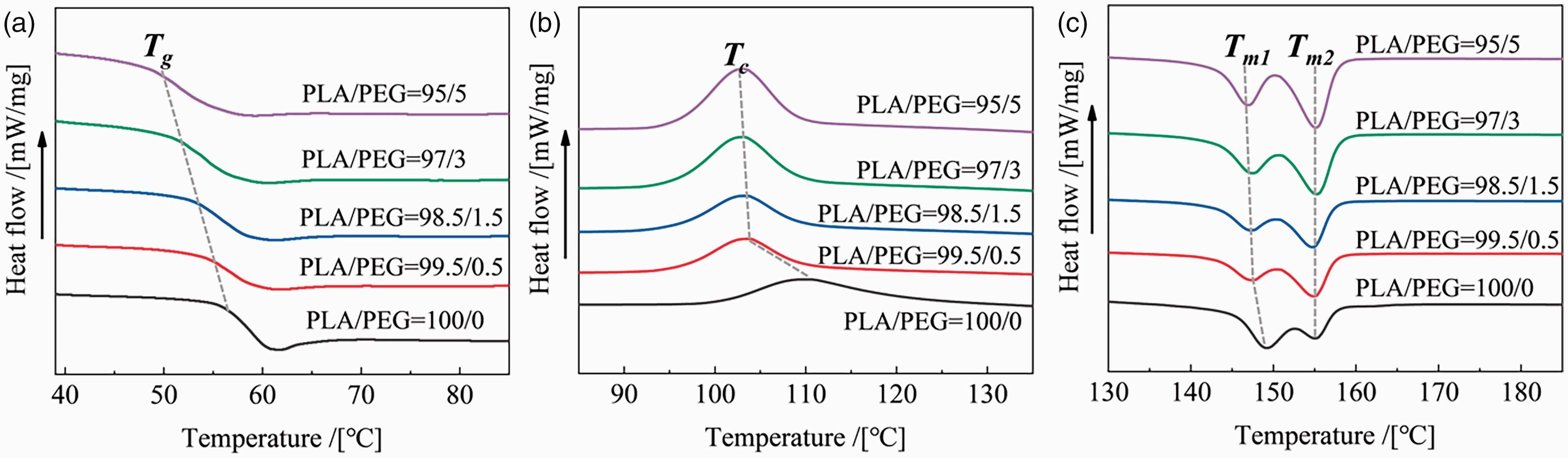
Second melting curves (a: 40–85°C, b: 85–130°C, c: 130–185°C) of the blended PLA/PEG polymers with different PEG mass ratios.
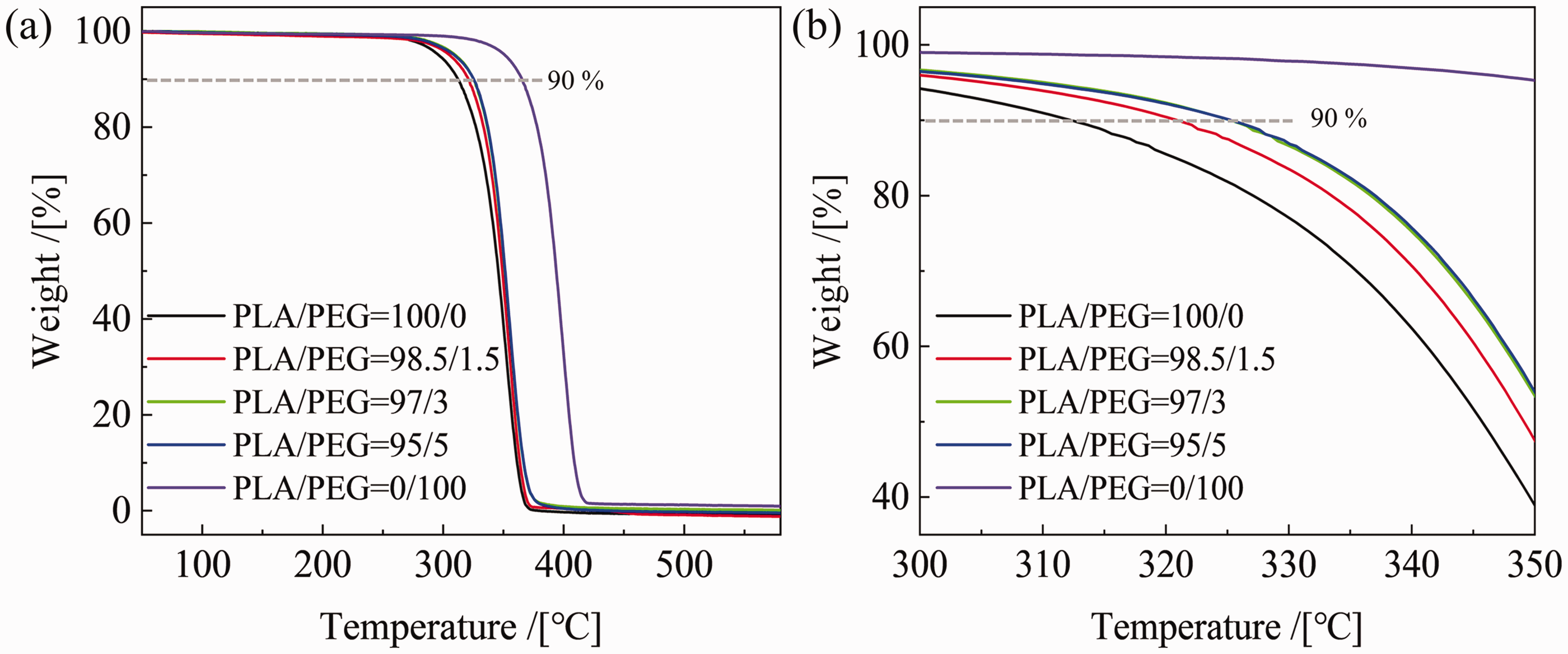
TGA curves (a: weight loss of 0–100%, b: weight loss of 40–100%) of the blended PLA/PEG polymers with different PEG mass ratios.
Morphology of the fluffy fibrous alignment structure
As depicted in the surface SEM images displayed in Figure 4(a) to (d), all the prepared PLA/PEG microfibrous membranes presented a typical nonwoven structure comprising smooth microfibers. 12 Meanwhile, these microfibers exhibited a remarkably high orientation isotropy, with almost all fibers aligned along the machine direction. A comparison of the distortion in fiber diameter of the samples with different PEG mass ratios has been displayed in Figure 4(e). The fibers became considerably thinner and the diameter distribution became narrower with the increase in PEG mass ratio. With the increase in PEG mass ratio from 0 to 5 wt%, the average diameter slightly decreased from 5.27 to 3.39 µm (Figure 4(e)), leading to an enhancement in the melt flow index from 39.3 to 68.4 g/10 min at 230°C (Figure S1 in the supporting information). Figure 4(f) shows the FTIR spectrum of the prepared PLA/PEG microfibrous membranes with different PEG mass ratios. The PLA/PEG microfibrous membranes show peaks at 1747 cm−1 due to the stretching vibration of the C=O groups. The peaks at 1181 cm−1 and 1080 cm−1 can be assigned to the stretching vibration bands of C-O groups of PLA/PEG microfibrous membranes. With the increase in PEG content, there is no significant change in the position of the peaks, and no new peaks appeared. This proves that no chemical reaction occurs between PLA and PEG during the spinning process. Figure 4(g) shows the XRD patterns of the prepared PLA/PEG microfibrous membranes with different PEG mass ratios. All diffraction patterns exhibit a characteristic peak at an angle of 2θ = 16.6°, corresponding to the (0 1 0) and (1 1 0/2 0 0) planes of PLA α crystals. 36 The intensity of this peak increased with the increase in PEG mass ratio, suggesting that the addition of PEG improved the PLA α phase crystallinity. This effect could be attributed to the effectiveness of the novel in situ drafting-assisted melt-blowing processing for taking up aligned microfibers. The temperature of the PLA/PEG microfibers near the die was above 60°C (Figure S2 in the supporting information shows the curves corresponding to temperature variation with displacement), and the PLA/PEG microfibers were aligned along the machine direction. These results show that the prepared PLA/PEG microfibrous membranes exhibit a specially aligned structure consisting of smooth microfibers, which would significantly enhance the comfort and wearability attributes including softness and air permeability. Figure 5(a) to (c) presents SEM images of the cross-sectional microstructures of the prepared PLA/PEG microfibrous membranes with various DCDs. The PLA/PEG microfibrous membranes possessed a fluffy alignment structure, and the membrane thicknesses varied from 0.329 to 0.532 mm (Figure 5(d)) due to the packing, adhesion, and bonding of neighboring microfibers. 40 These cross-sectional SEM images also demonstrate that the porosity of the fibrous material gradually diminished from 75.8 to 86.1% (Figure 5(e)) as the DCD increased from 14 to 37 cm, suggesting that the entanglement between the microfibers had weakened. Thus, the overall resistance to deformation under the impact of an external force was minimized.
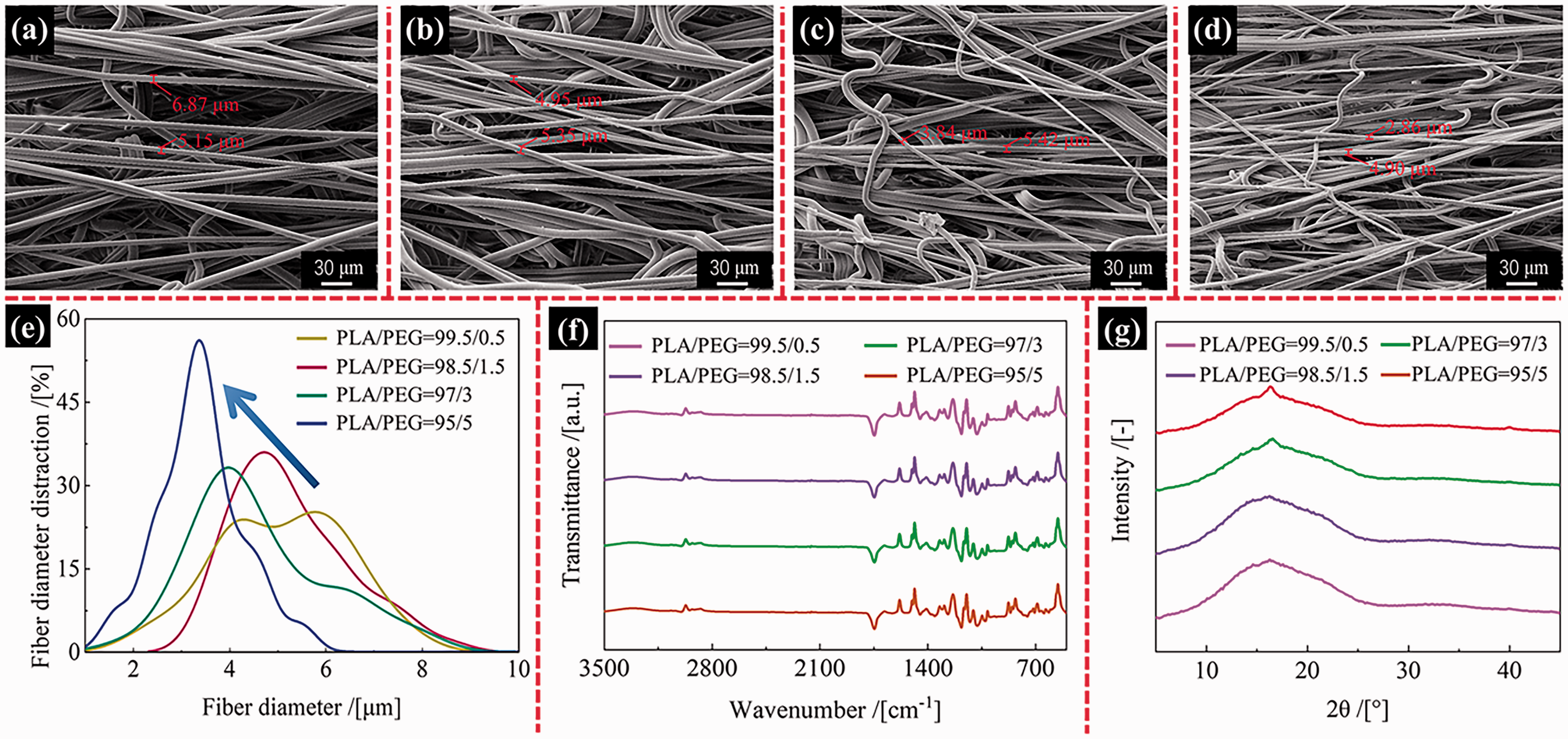
SEM images of the surface of prepared PLA/PEG microfibrous membrane samples with various PEG mass ratios: (a) PLA/PEG = 99.5/0.5, (b) PLA/PEG = 98.5/1.5, (c) PLA/PEG = 97/3, and (d) PLA/PEG = 95/5 and (e) fiber diameter distortion, (f) FTIR, and (g) XRD spectra of the prepared PLA/PEG microfibrous membranes samples with varying PEG mass ratios prepared with a DCD of 23 cm.
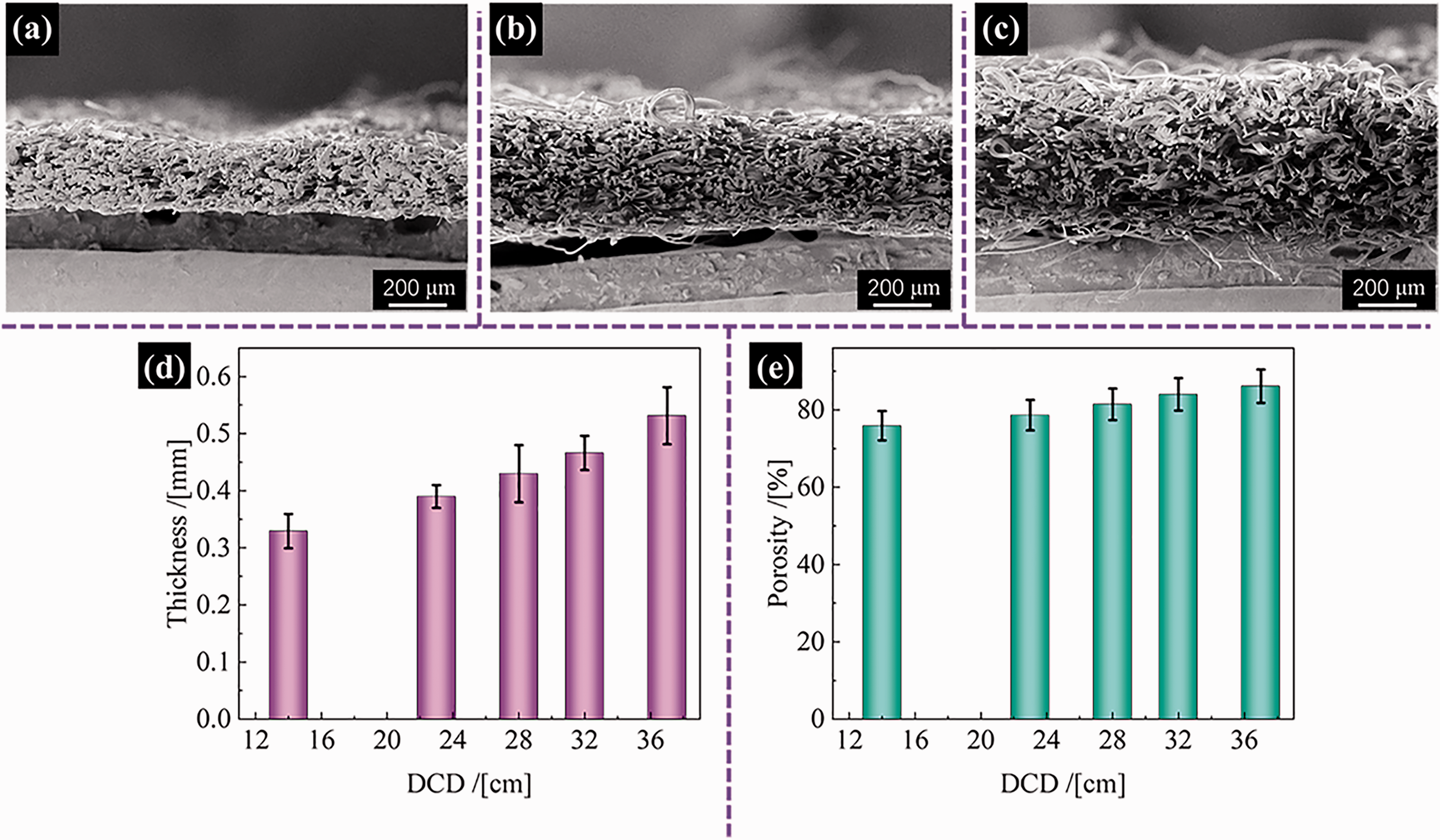
Cross-sectional SEM images of the prepared PLA/PEG microfibrous membrane samples with DCDs of (a) 14 cm, (b) 23 cm, and (c) 28 cm; (d) thickness and (e) porosity variation with varying DCD for the membrane samples prepared with a PEG mass ratio of 3%.
Softness properties
A PhabrOmeter system and Handle-O-Meter method were used to evaluate the softness performance of the prepared PLA/PEG microfibrous membranes, and the resistance force–displacement curve thus generated reflected the softness properties. The softness scores of the PLA/PEG microfibrous membrane samples (Figure 6(a) and (b)) were obtained from these force–displacement curves (Figure 6(c) and (d)). The testing process has been illustrated in Figure 6(e) and Movie S1 in the supporting information. As displayed in Figure 6(a), the softness scores of the PLA/PEG microfibrous membranes increased from 50.78 to 75.84, as the PEG concentration increased, indicating effortless compression and squeezing in a piece of membrane sample crumpled by hand. In addition, the softness scores of the prepared samples increased from 65.72 to 78.39, as the DCD increased from 14 to 37 cm, as illustrated in Figure 6(c). This result indicated the noticeable softness of the PLA/PEG microfibrous membranes with fluffy structures. This noticeable softness effect was presumably the result of the intrinsically high softness of the PLA/PEG microfibers and the sparse bonding points between fibers.
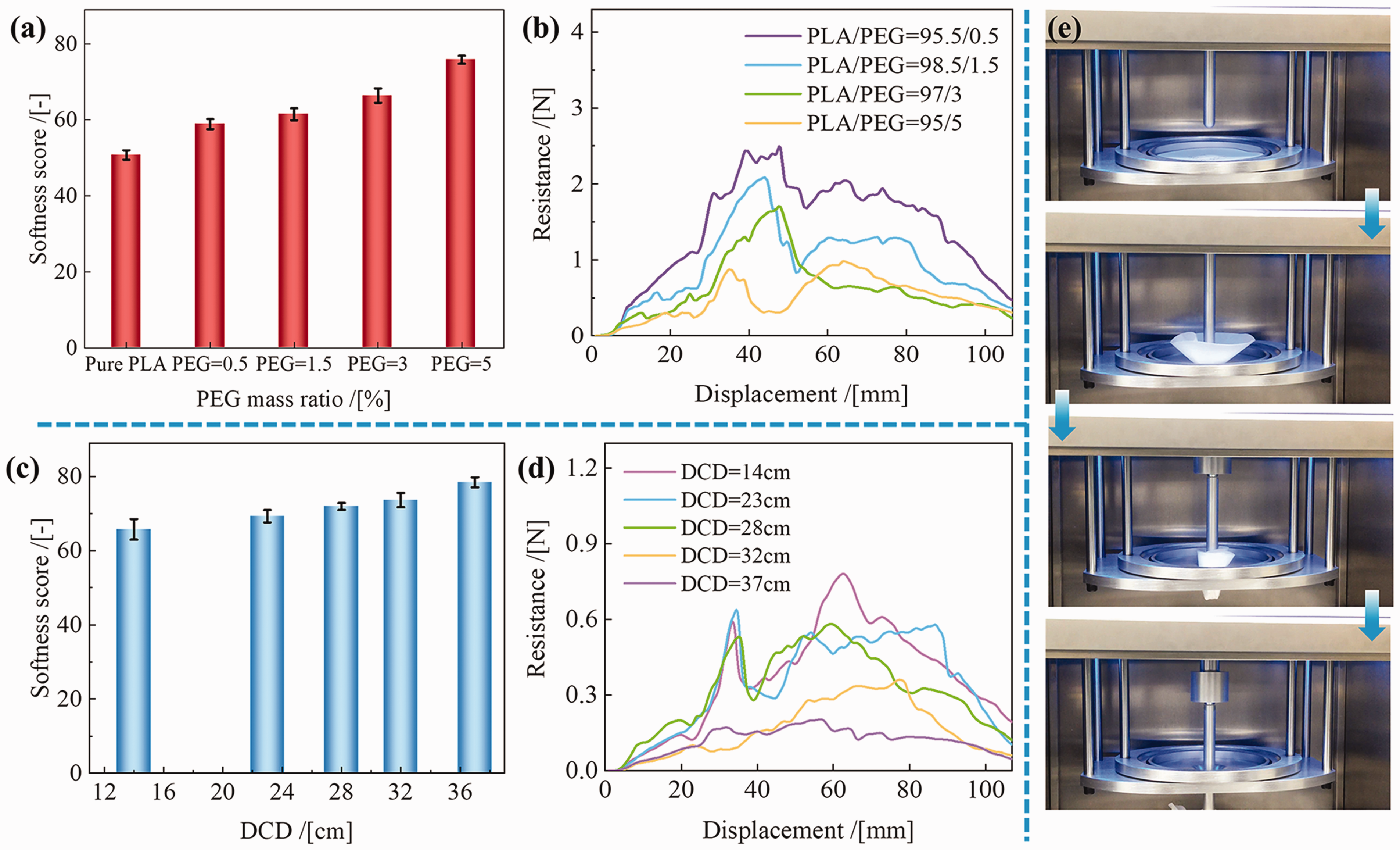
Softness scores and resistance force–displacement curves of the PLA/PEG microfibrous membrane samples with different (a, b) PEG mass ratios and (c, d) DCD values, obtained using (e) a PhabrOmeter system.
The softness performance of the prepared samples in the machine direction and cross direction was further quantified via homemade equipment based on the Handle-O-Meter method. The testing progress has been depicted in Figure 7(a) and Movies S2–S3 in the supporting information. The real-time resistance–displacement curves are presented in Figures 7(b) and (c). The resistance–displacement curves of the membranes were similar and could be separated into three stages. In the first stage, the resistance significantly increased with increasing displacement as the microfibrous membranes were gradually deformed and pushed into the slit. The fiber alignment structure of the microfibrous membranes was crucial to their behavior and softness performance, 41 and resistance mainly arose from the deformation resistance and friction between the samples and slit at this stage. For the cross direction in general (Figure 7(d)), the sample deformation resistance was caused by the bending of the aligned fibers. Moreover, the maximum resistance decreased as the PEG mass ratio increased. The maximum resistance values of the membranes prepared with PEG mass ratios of 0 (pure PLA), 0.5, 1.5, 3, and 5 wt% were 3.1, 2.7, 2.3, and 1.8 N, respectively. In comparison, the sample deformation resistance was generally caused by fiber slipping in the machine direction. Smaller maximum resistances of 0.39, 0.25, 0.18, and 0.13 N were obtained in this direction. The samples were gradually driven into the slit under the force of the side head’s plate-like structure during the second stage when the resistance was comparatively stable. As the samples completely inserted themselves inside the slit in the third stage, the resistance finally decreased. The anisotropic softness of the PLA/PEG microfibrous membranes was overall outstanding.
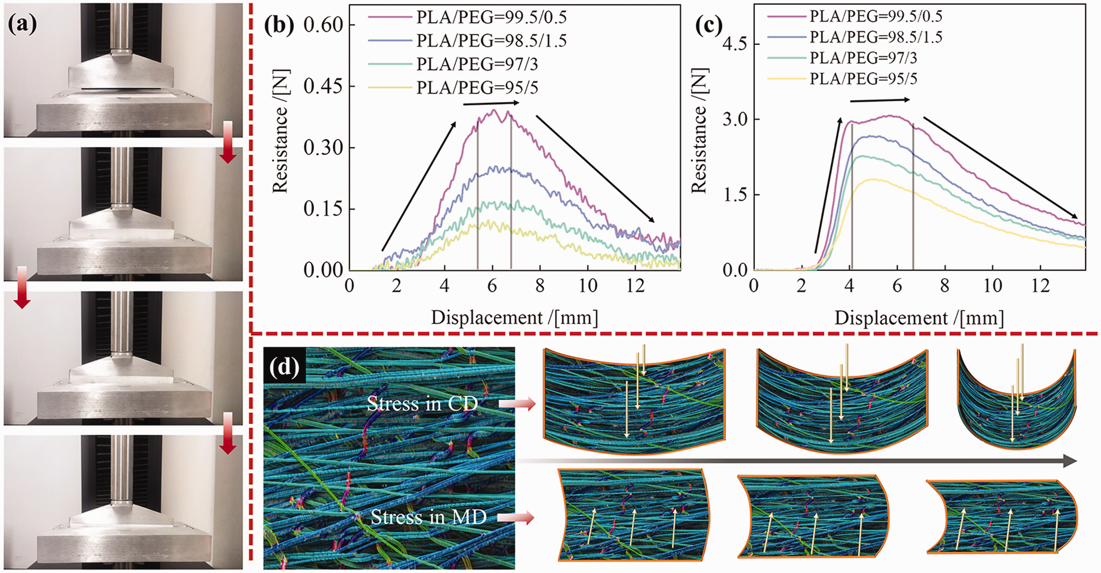
(a) Tensile testing system according to the Handle-O-Meter method. Resistance–displacement curves and (d) the deformation mechanism of the PLA/PEG microfibrous membrane samples with different PEG mass ratios in the (b) machine direction (MD) and (c) cross direction (CD).
Air permeability
The air permeability of a skin contactor is one of its most crucial properties. Air permeability, in turn, is related to structural characteristics such as porosity and fiber diameter. In this work, experimental testing was used to aid a virtual simulation method to estimate the air permeability performance of the microfibrous membranes. As displayed in Figure 8(a) and (b), the air permeability of the PLA/PEG microfibrous membranes increased from 71.5 to 142.5 mm/s as the DCD increased to 37 cm, which was consistent with previous studies. Additionally, as the PEG concentration increased, the air permeability of the PLA/PEG microfibrous membranes decreased from 149.4 to 65.5 mm/s, indicating excellent wearing comfort. The FiberGeo module of GeoDict was used to create virtual PLA/PEG microfibrous membranes with fluffy alignment structures based on the structural characteristics of the manufactured membranes. These virtual membranes’ material air permeability was determined using GeoDict’s FlowDict module. The established aligned fibrous structure and the boundary conditions are shown in Figure S3, and the pore size distribution of the virtual microfibrous membranes is shown in Figures S4 and S5. The theoretical air pressure along the thickness of the membranes is displayed in Figure 8(c) and (d). The results showed that the air pressure field decreased with the decrease in mean fiber diameter as well as with the reduction in porosity. This was in good agreement with the experimental results. The outcome is potentially on account of the significant increase in fiber number with the decrease in PLA/PEG microfiber mean diameter leading to an eventual decrease in mean pore size, as shown by the virtual microfibrous membranes displayed in the inset of Figure 8(e) to (m). Thus, the air permeability decreased with increased energy absorption as air passed through the microfibrous membranes. These results indicate that in comparison with the traditional melt-blown microfibrous membranes with randomly distributed fibers, the microfibrous membranes with a fluffy alignment structure exhibit excellent and controllable air-penetration properties. 42
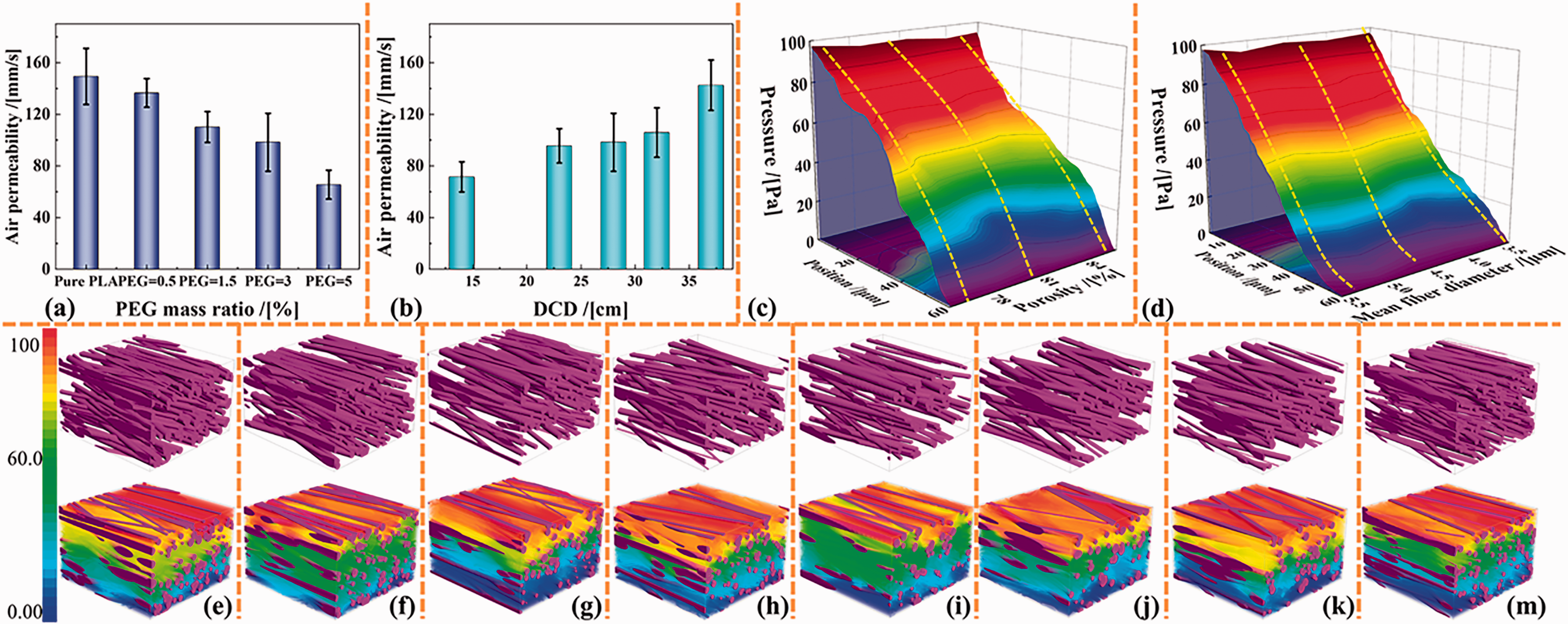
Air permeability of the PLA/PEG microfibrous membrane samples with different (a) PEG mass ratios and (b) DCDs; (c) 3D diagram of the virtual pressure against the thickness position and porosity during the vertical air permeability simulation for the virtual microfibrous membranes with a mean fiber diameter of 4.0 μm. Virtual pressure results for the virtual microfibrous membranes with different porosities of (e) 75.89, (f) 78.62, (g) 81.42, (h) 84.01, and (i) 86.12%; (d) 3D diagram representing the virtual pressure against the thickness position and mean fiber diameter, during the vertical air permeability simulation for the virtual microfibrous membranes with a porosity of 84.01%. Virtual pressure results for the virtual microfibrous membranes with mean fiber diameters of (j) 5.08, (k) 4.56, and (m) 3.40 μm.
Strength performance
The strength of membranes is an important factor affecting their successful application as skin contactors. Therefore, the tensile strength and elongation at the break of the PLA/PEG microfibrous membrane samples were evaluated. Figure 9 shows the force–displacement curves of the PLA/PEG microfibrous membrane samples obtained as a result of tensile strength testing. The tensile strengths of the pure PLA microfibrous membrane (PEG mass ratio of 0 wt%) in the machine direction and cross direction were 74.4 N and 7.7 N, respectively. In contrast, the PLA/PEG microfibrous membrane with a PEG mass ratio of 5 wt% had higher tensile strengths of 101.4 N and 15.8 N in the machine direction and cross directions, respectively. As the PEG mass ratio grew from 0 to 5 wt%, tensile breaking strength and the elongation at break in the machine direction and cross direction likewise increased. These findings point to the exceptional tensile strength of the fabricated PLA/PEG microfibrous membranes’ performance and could be attributed to the fact that the addition of PEG reduces the intermolecular force of PLA, which makes the fiber more prone to orientation deformation when drawn by wind pressure, and improves the toughness of the fiber itself.
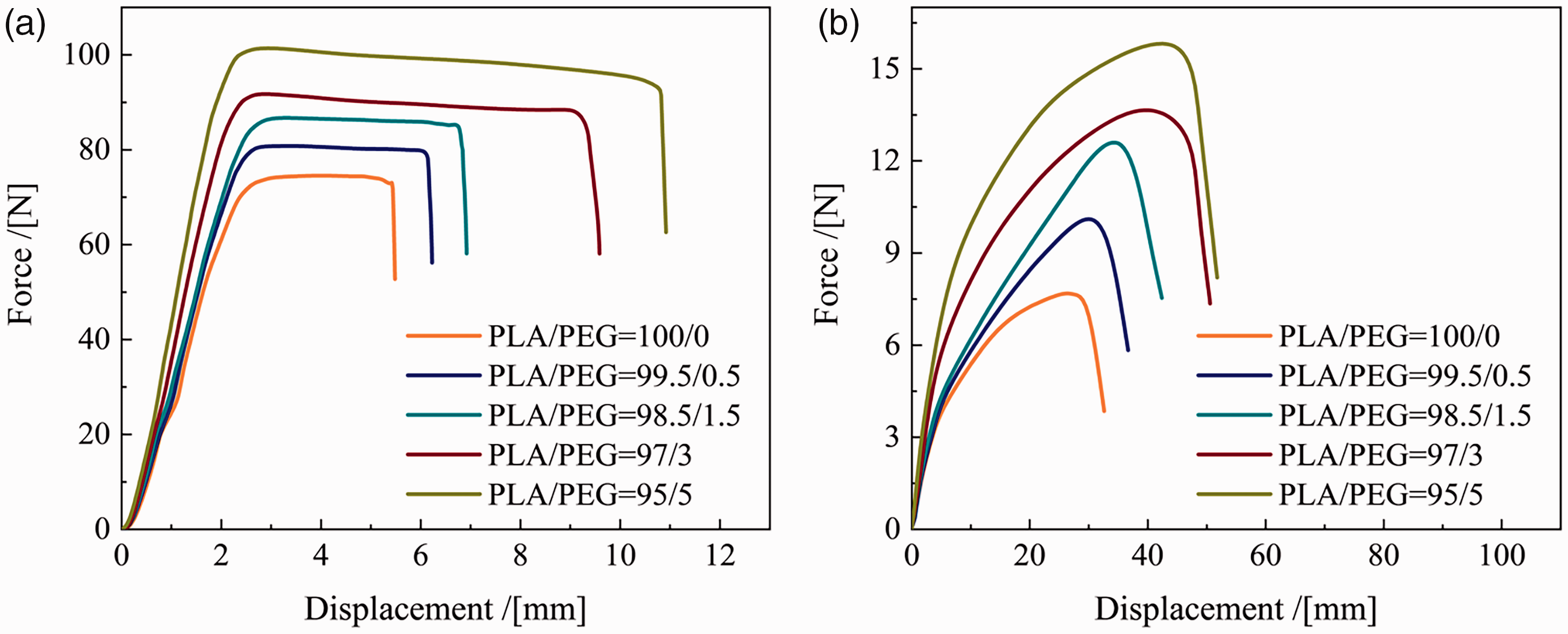
Force–displacement curves of the PLA/PEG microfibrous membranes with various PEG mass ratios in the (a) machine direction (MD) and (b) cross direction (CD).
In addition, the tensile breaking strength in the machine direction is greater than that in the cross direction, while the tensile breaking elongation is less than that in cross direction. This is because the fiber arrangement is more along the machine direction, the machine direction tensile fiber is more stressed, but in addition to the toughness elongation of the fiber itself, the tensile break elongation is affected by the slip between the fibers when stretched, and the fiber film along the cross direction is more prone to relative slip than along the machine direction, so the fiber film produces greater tensile break elongation.
Conclusion
In conclusion, PLA/PEG microfibrous membranes with a high alignment, high porosity, excellent softness, and excellent air permeability were successfully prepared by a large-scale in situ drafting-assisted melt-blowing process. The thermal properties of the blended PLA/PEG polymer were regulated by PEG concentration, to achieve an intense plasticizing effect and improved thermal stability. This enhanced crystallization promotes the crystallinity of the PLA phase to a great extent. The Tg of the PLA/PEG blended polymer decreased by 6°C in comparison with the neat polymer, and the temperature of the cold crystallization peak decreased to 102.97°C when the PEG mass ratio was increased to 5%. SEM analysis demonstrated that the fibers were aligned along the machine direction and that the fiber diameter decreased slightly from 5.27 to 3.39 μm with the increase in PEG mass ratio. In addition, in the synergy of the PEG and the drafting process, the prepared PLA/PEG microfibrous membranes exhibited a special fluffy alignment structure consisting of thinner, narrower, and more aligned microfibers. The PLA/PEG microfibrous membranes manifested a high porosity of 86.1% and the air permeability increased to 142.5 mm/s as the DCD increased to 37 cm. Meanwhile, softness studies revealed that the fluffy alignment structure had an impressive anisotropic softness. Also, the tensile strength of the membrane sample with a PEG mass ratio of 5 wt% was 101.4 and 15.8 N in the machine direction and cross direction, respectively. This work, thus, demonstrates that PLA/PEG microfibrous membranes with a fluffy alignment structure demonstrate excellent potential for application as skin contactors, providing outstanding wearing comfort.
Footnotes
Declaration of competing interest
The author(s) declare that they have no known competing financial interests or personal relationships that could have appeared to influence the work reported in this paper.
Funding
The author(s) disclosed receipt of the following financial support for the research, authorship, and/or publication of this article: This work was supported by the National Natural Science Foundation of China (52003306), Major Projects of Science and Technology in Henan province, China (221100310500), and Key Research Projects of Henan Higher Education Institutions, China (23A540003).