
Abstract
Spacer fabrics are widely used in personal protection, automotive interiors, and medical support owing to their lightweight, breathable, and cushioning properties. However, their application in durability-critical scenarios is limited by insufficient resilience, associated with plastic deformation accumulation during compression. This is governed by the deformation of load-bearing spacer monofilaments. Owing to initial curvature and torsion, they experience combined bending and axial compression, leading to longitudinal strain concentration and asymmetric cross-sectional tensile–compressive strain distribution. In this paper, the role of initial configuration governing the evolution of bending–axial compression coupling and the resulting strain distribution is investigated to identify strategies for resilience improvement. Based on a validated finite-element model, the evolution of bending–axial compression coupling is examined, and strain responses along both longitudinal and cross-sectional directions are quantified in terms of maximum strain, compressed area ratio, and neutral axis offset. Results show that, in the linear elasticity stage, coupling is weak, exhibiting uniform longitudinal strain but compression-dominated cross-sectional distribution. In the subsequent deformation stages, bending becomes dominant, inducing strain concentration and shifting the neutral axis toward the centroid. Longitudinal strain localization is configuration-dependent: curvature determines strain concentration, while torsion modulates deformation distribution. Moderate curvature and torsion balance load-bearing capacity and resilience. Radial strain distribution shows that damage is dominated by the coexistence of high strain and a 50% compressed area, regardless of configuration. The near 1:1 tensile–compressed area ratio suggests that bicomponent monofilaments, combining tension- and compression-resistant materials, offer a promising strategy for enhanced durability and compression resilience.
Keywords
Spacer fabrics have found application as structure–function integrated materials, such as are used in personal protection, automotive interiors, and medical support, owing to their light weight, high air permeability, and excellent cushioning performance.1–6 However, under long-term cyclic compression, they are prone to irreversible structural collapse, limiting their use in durability-critical scenarios, such as mattresses and car seats. This inadequate resilience is primarily attributed to the accumulation of plastic deformation during compression, which is governed by the deformation modes of the structure. As shown in Figure 1, spacer fabrics have a 3D sandwich architecture, where two surface layers are connected by numerous spacer monofilaments that form the primary load-bearing paths. These monofilaments develop spatial configurations with initial curvature and torsion during knitting and heat-setting processes.7–11 Under compressive loading, the deformation of the monofilaments involves not only axial compression but also bending. Therefore, the strain distribution arising from the evolving bending–axial compression coupling is key to understanding the mechanism of resilience insufficiency of spacer fabrics.
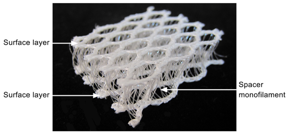
Typical 3D spacer fabric.
Existing studies for addressing insufficient resilience are mainly focused on material substitution and structural optimization. For example, bamboo-like hollow monofilaments have been designed to increase the bending stiffness per unit mass, thereby suppressing excessive buckling deformation and improving structural recoverability. 12 However, such an approach remains at the proof-of-concept stage, based on 3D printing. More feasible approaches include manipulation of the spatial configuration of spacer monofilaments to maintain higher straightness 13 and integration of thermoplastic components in the surface layers to form bonding constraints after heat-setting. 14 These methods improve resilience by increasing structural stiffness and suppressing global deformation, thereby reducing macroscopic compressive strain under a given load and limiting monofilament damage. While these strategies act at the fabric scale, the underlying mechanisms at the monofilament scale, where strain localization and damage potentially originate, are still not fully understood.
From a mechanistic perspective, an understanding of the mechanical behavior during compression is fundamental to improving resilience. Previous studies have shown that spacer fabrics exhibit a typical nonlinear stress–strain response under compression, including a linear elasticity stage, a plateau stage, and a densification stage. This nonlinear response arises from the complex behavior of spacer monofilaments, including post-buckling, shear, and rotation, as well as contacts between monofilaments and between monofilaments and surface layers.15–19 In addition, monofilament configuration and fabric structural parameters substantially affect the load-bearing performance. Larger yarn inclination angles, finer spacer yarns, sparser yarn arrangements, higher fabric thicknesses, and larger surface mesh sizes would have a lower compression resistance.20–24 Monofilaments with greater length, curvature, or torsion tend to exhibit lower compression resistance. 25 However, existing studies are focused on geometric deformation, with limited attention to the internal force state of the monofilaments, which governs strain distribution and the resulting plastic deformation. Only one study, 26 to the authors’ knowledge, was designed to examine the location of maximum strain in monofilaments, showing that the maximum strain typically occurs near the mid-length and is associated with bending deformation. It was also reported that the evolution of maximum strain is consistent with the macroscopic compressive response of the fabric, increasing in the linear elasticity stage, remaining relatively stable in the plateau stage, and increasing significantly in the densification stage. However, this analysis was focused solely on maximum strain, leaving the underlying internal force state and the evolution of strain distribution unexplored. Since resilience is governed by the coupled force–deformation response of the entire monofilament, a more comprehensive investigation is required.
In this study, the role of the initial configuration in governing the evolution of bending–axial compression coupling and the resulting strain distribution in spacer monofilaments was investigated to identify strategies for resilience improvement. Based on a validated finite-element (FE) model, three representative monofilaments with varying values of initial curvature and torsion were selected. The evolution of bending–axial compression coupling was analyzed to reveal its governing role in strain distribution, while the strain response along both longitudinal and radial directions was quantitatively characterized in terms of maximum tensile or compressive strain, cross-sectional compressed area ratio, and neutral axis offset. The findings provide mesoscale insight into the compression deformation of spacer fabrics and can be used to form a theoretical basis for improving their resilience.
Material and methods
Fabric details
The spacer fabric used in this study is shown in Figure 1. It was produced on an E12 RD6/3-15 double-bar Raschel warp knitting machine (Karl Mayer, Germany) equipped with six guide bars (numbered GB1 to GB6). The two surface layers were formed as mesh structures by chain plus inlay, using four sets of 600D/192F polyethylene terephthalate (PET) multifilament yarns and GB1, GB2, GB5, and GB6. Spacer connections between the two surface layers were created using rigid PET monofilaments with a diameter of 0.22 mm, which were threaded through GB3. The chain notations and yarn specifications used are summarized in Table 1. After knitting, the fabric was subjected to a stentering and heat-setting treatment at 200°C for 30 s. The finished spacer fabric has a thickness of 10.3 mm, a stitch density of 7 wales/inch and 18.5 courses/inch, and an areal density of 550 g/m2.
Chain notations and yarn materials used for 3D spacer fabric
FE model establishment and validation
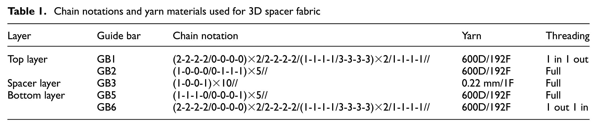
The FE model was created using ANSYS, as shown in Figure 2. The unit cell geometry was reconstructed from micro-computed tomography (µCT), as reported previously. 9 Owing to the limited resolution of µCT, only two separate wales of monofilament were imaged. The unit cell has a length of 14 mm, a width of 7.5 mm, and a thickness of 10.05 mm.
Finite-element compression model of a unit cell of 3D spacer fabric. DOF, degree of freedom
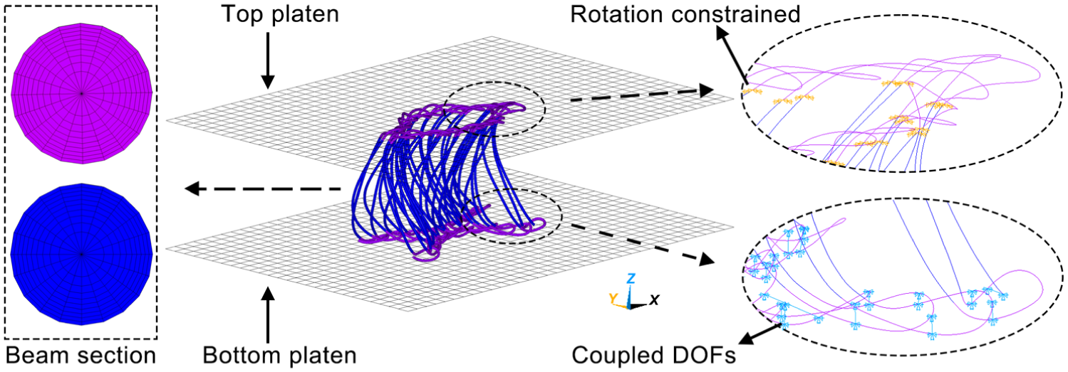
Monofilaments were meshed using BEAM188 elements with a length of 0.05 mm to balance computational accuracy and efficiency. Each beam had a circular cross-section with a diameter of 0.22 mm and was divided into 20 sectors. Each sector was further divided into 10 elements, each with an area of 1.89 × 10⁻⁴ mm2. The tensile stress–strain curves of PET monofilaments, with a Young’s modulus of 3540.8 MPa, are shown in Figure 3. A multilinear kinematic hardening model was adopted to represent the material behavior, with a Poisson’s ratio of 0.3 and a friction coefficient of 0.27. Multifilament chains and inlays of two surface layers were geometrically neglected but physically simulated by coupling the translational degree of freedom (DOF) of the x-axis between two adjacent monofilament loops. The bindings of multifilament loops on monofilaments were simulated by constraining the rotational DOFs of x- and y-axes (ROTX and ROTY) at the breakpoints of spacer monofilaments and monofilament loops, as defined elsewhere. 9 Two rigid rectangular compression platens were meshed with shell elements of 1 mm edge length. All translational and rotational DOFs of the bottom platen were fixed, while a prescribed displacement of −8.5 mm was applied to the top platen, with all other DOFs constrained. Contacts between monofilaments were modeled using 3D line-to-line self-contact pairs (CONTA176 and TARGE170). Contacts between monofilaments and the rigid platens were simulated using 3D flexible line-rigid surface contact pairs (CONTA177 and TARGE170). Large-deformation effects were included by activating the NLGEOM option. Then the FE model was solved.
Tensile stress–strain curves and multilinear kinematic hardening model of polyethylene terephthalate monofilament.
The fabric sample, consisting of 7 × 13 unit cells, was tested using a universal testing machine (Instron 5566) at a compression speed of 10 mm/min. It should be noted that the experimental validation was conducted at the fabric level, whereas the FE model simulated a single unit cell and was subsequently used for monofilament-level analysis. The simulated load–displacement curve was obtained by scaling the single-unit-cell response by 91 and compared with the experimental results, as shown in Figure 4. The simulated compression curve successfully reproduces the three distinct stages: linear elasticity, plateau, and densification. In the linear elasticity stage, good agreement between simulation and experiment can be observed. In the plateau stage, the simulated load drop is more pronounced than that observed in the experiment; this can be attributed to the absence of lateral constraints from neighboring unit cells in the model, leading to easier slip of the simulated structure. In the densification stage, the simulation underestimates the compression load because only a single unit cell is modeled. Since densification stage is mainly governed by extensive contacts between spacer monofilaments and between spacer monofilaments and surface layers, 26 the reduced number of contact interactions in the model results in a smaller predicted load. Figure 5 is a comparison of the von Mises strain distribution from the simulation and photographs of the compressed fabric. The simulated deformation pattern of the spacer monofilaments agrees well with the experimental observations, indicating that the developed FE model can reasonably capture the compression deformation behavior of the spacer fabric.
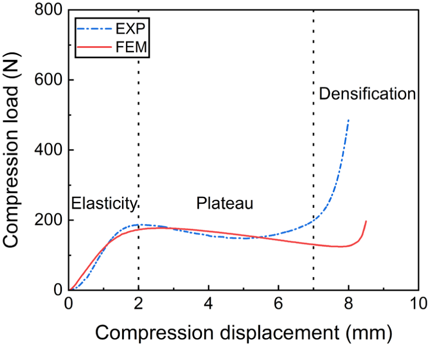
Simulated and experimental compression load–displacement curves. FEM, finite-element model.
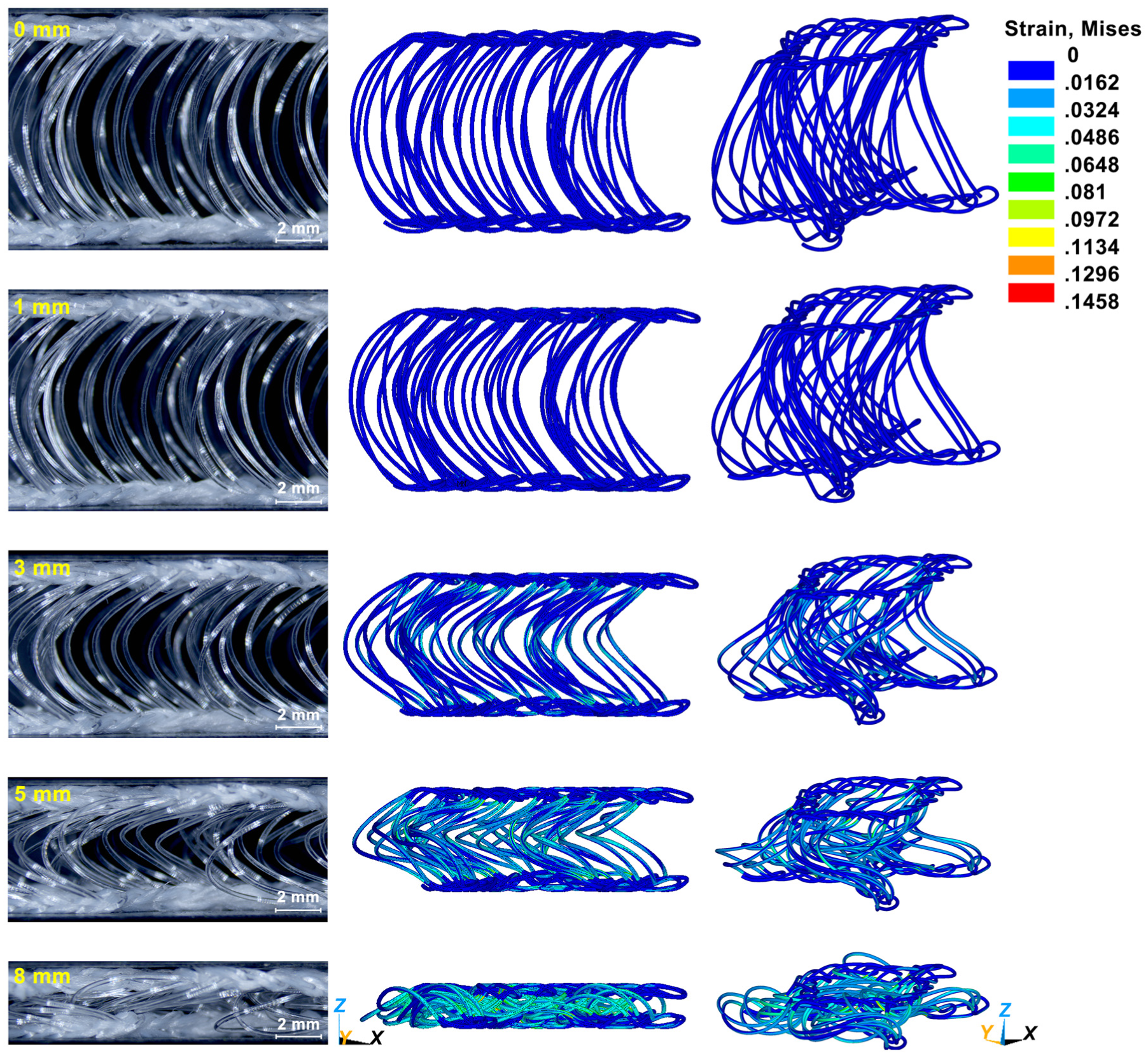
Fabric side views and von Mises strain plots of finite-element model at different compression displacements.
Results and discussion
In spacer fabrics, when a through-thickness compressive load is applied, the loading direction does not coincide with the monofilament centerline, generating force components both along and transverse to the monofilament centerline. The transverse component induces bending, while axial shortening occurs simultaneously. As a result, the monofilament is subjected to a combined loading state of axial compression and bending. This loading state leads to two key effects.
Bending causes nonuniform longitudinal strain distributions, leading to strain concentrations in regions of higher curvature.
Superimposed axial compression displaces the neutral axis from the centroid, producing an asymmetric tensile–compressive strain distribution within cross-sections.
To quantify the effects of combined bending and axial compression on strain distribution, three representative monofilaments were selected for analysis. Their spatial positions are shown in Figure 6(a), and their geometric configurations are presented in Figure 6(b). In the walewise–thickness plane, all the three monofilaments exhibit a uniformly inclined C-shaped projection. In the coursewise–thickness plane, the projections appear either inclined S-shaped or nearly vertical. Based on these characteristics, the monofilaments are denoted as i1, i2 (inclined type), and v1 (vertical type). Their curvature and torsion 27 distributions are shown in Figure 6(c), characterizing deviations from straight and planar configurations. Monofilament i1 exhibits the largest curvature variation and torsion magnitude, with alternating positive and negative torsion, reflecting pronounced spatial twisting. Monofilament v1 shows lower curvature and predominantly positive torsion, suggesting a more uniform twisting direction. Monofilament i2 has curvature comparable to v1 and torsion with alternating signs but smaller magnitude than i1, representing an intermediate configuration between i1 and v1. These results classify the monofilaments into three types:
a strongly curved–twisted configuration (i1), characterized by large curvature variation and alternating torsion;
a weakly curved configuration with predominantly unidirectional torsion (v1);
an intermediate configuration (i2) combining features of weakly curved and relatively strongly twisted configurations.
All beam elements constituting each monofilament were extracted for post-processing. As illustrated in Figure 7(a), each beam element in ANSYS is defined by nodes i, j, and k. Nodes i and j determine the local x-axis direction (from i to j), and the plane perpendicular to the x-axis direction is defined as the yoz-plane. Figure 7(b) illustrates the sectional parameters employed in this study, including the maximum tensile strain, maximum compressive strain, and neutral axis offset. The maximum tensile and compressive strains characterize the deformation magnitude. The neutral axis offset reflects the asymmetry of the tensile–compressive strain distribution within the cross-section, which in turn influences material utilization.
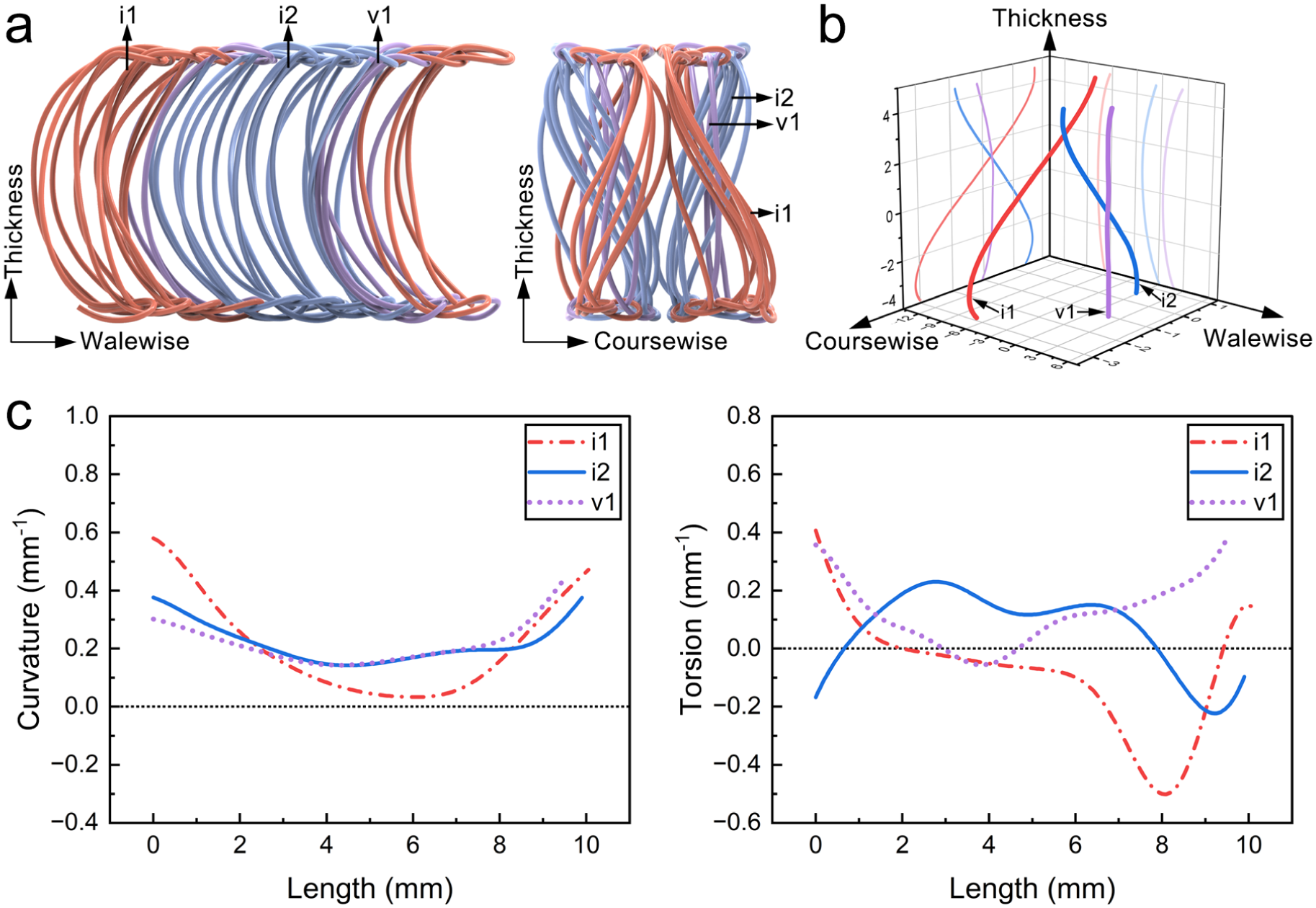
Three representative monofilaments: (a) spatial positions of selected monofilaments within unit cell; (b) geometric configurations and planar projections; (c) curvature and torsion distribution.
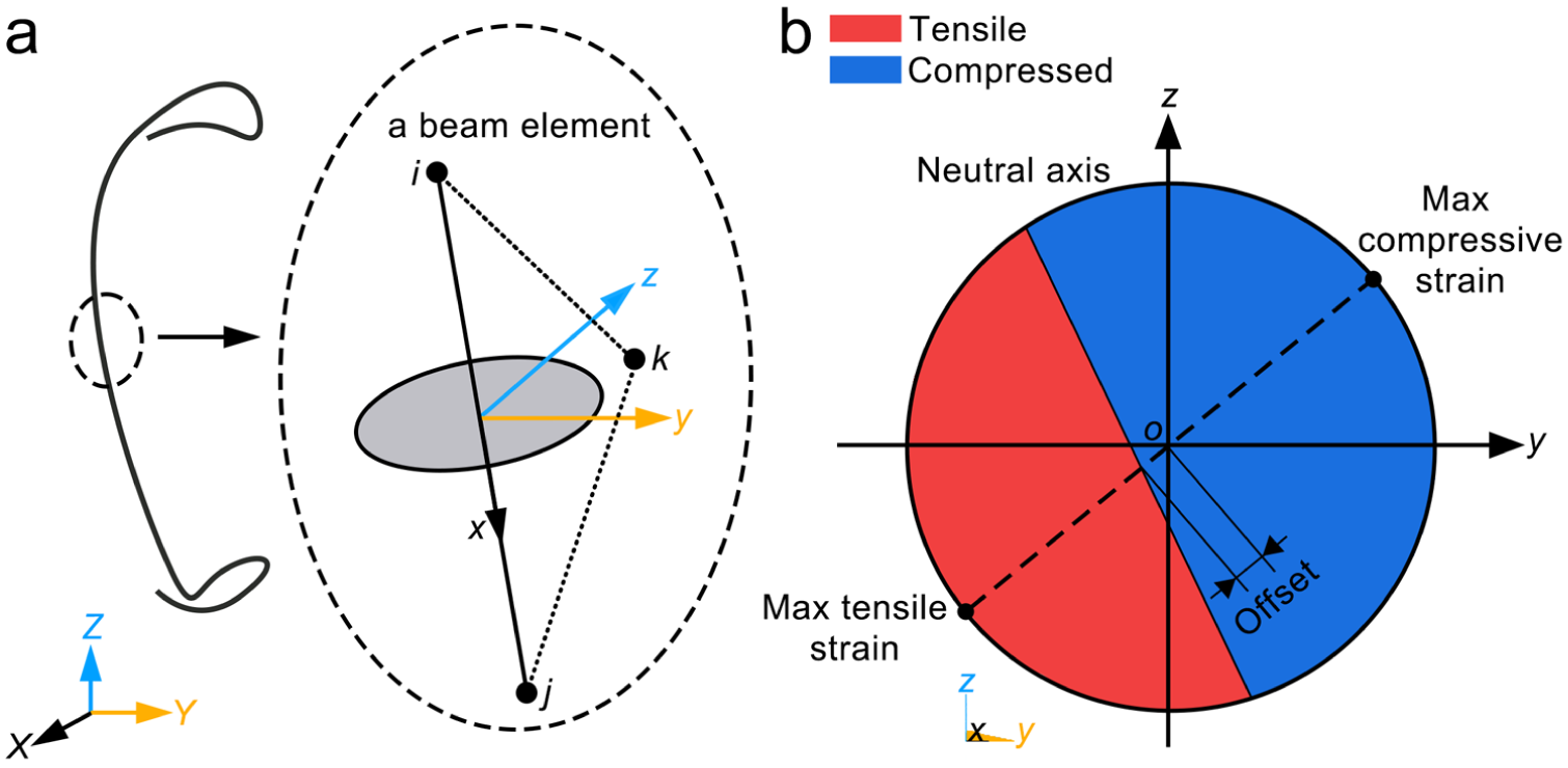
Beam element description and strain characterization method: (a) definition of beam element and local coordinate system; (b) sectional parameters.
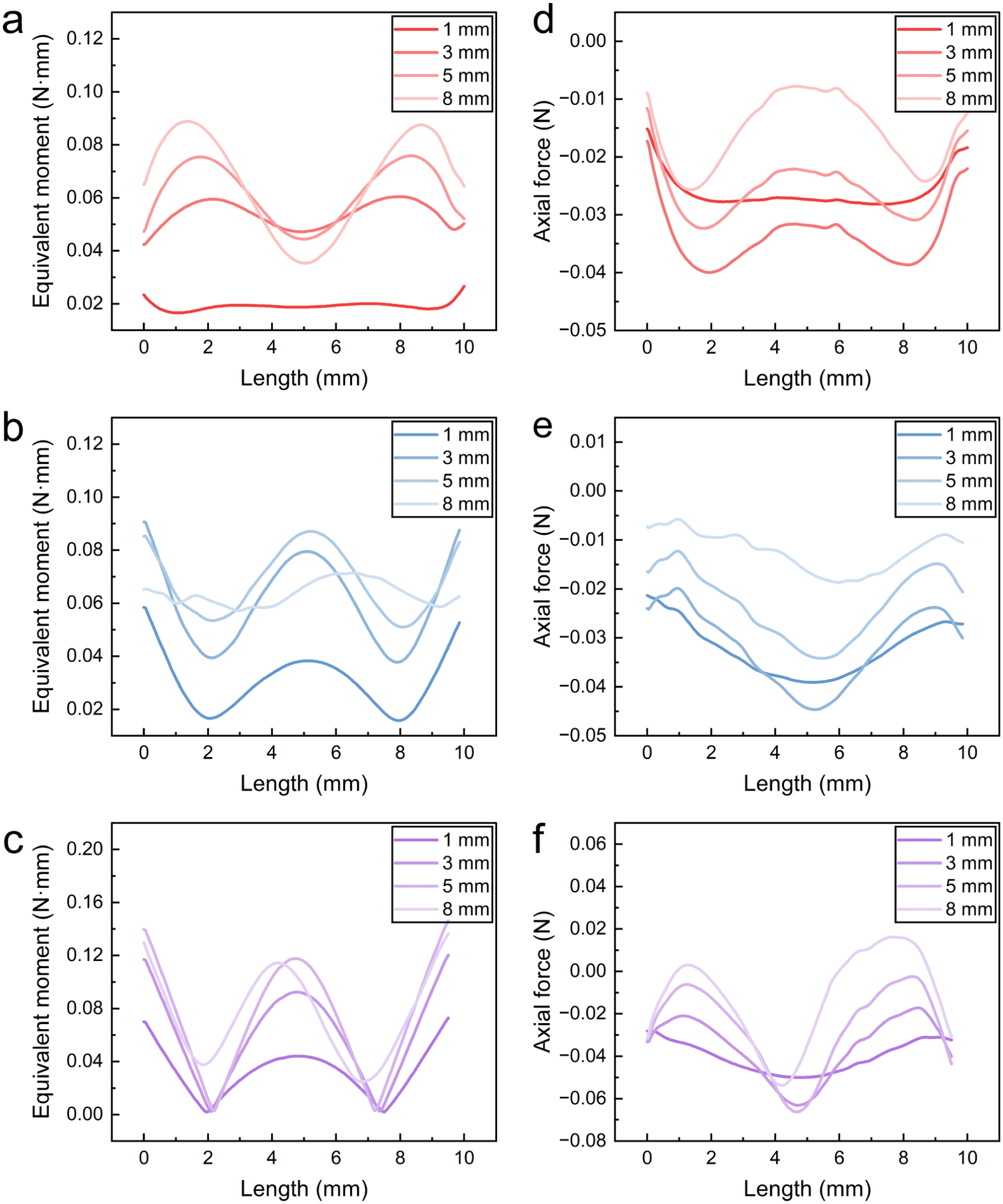
The mechanical response is determined by the combined action of axial force and bending moment. For a spatial elastic rod, the moment comprises a torsional component along the rod axis and two bending components perpendicular to it. In the beam elements used in this study, bending is described by the moment components
Longitudinal strain distribution and its governing mechanism
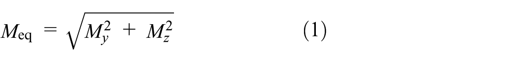
Figure 8(a)–(c) presents the distributions of the maximum tensile strain and maximum compressive strain at each cross-section along the monofilament length at different compression depths. Specifically, for each cross-section, the maximum tensile and compressive strains were extracted and assigned to the corresponding position along the monofilament centerline. These sectional extreme strains were used to characterize the longitudinal variation and the concentration of the strain along the length. Figure 8(d)–(f) summarizes the mean value and standard deviation of the sectional maximum strains along the monofilament length at different compression depths. These statistical measures quantify the overall strain level and its dispersion along the monofilament. The recovery regions of PET are highlighted, where strains less than 1% correspond to the instant recovery region, and strains less than 5% correspond to the delayed recovery region.
28
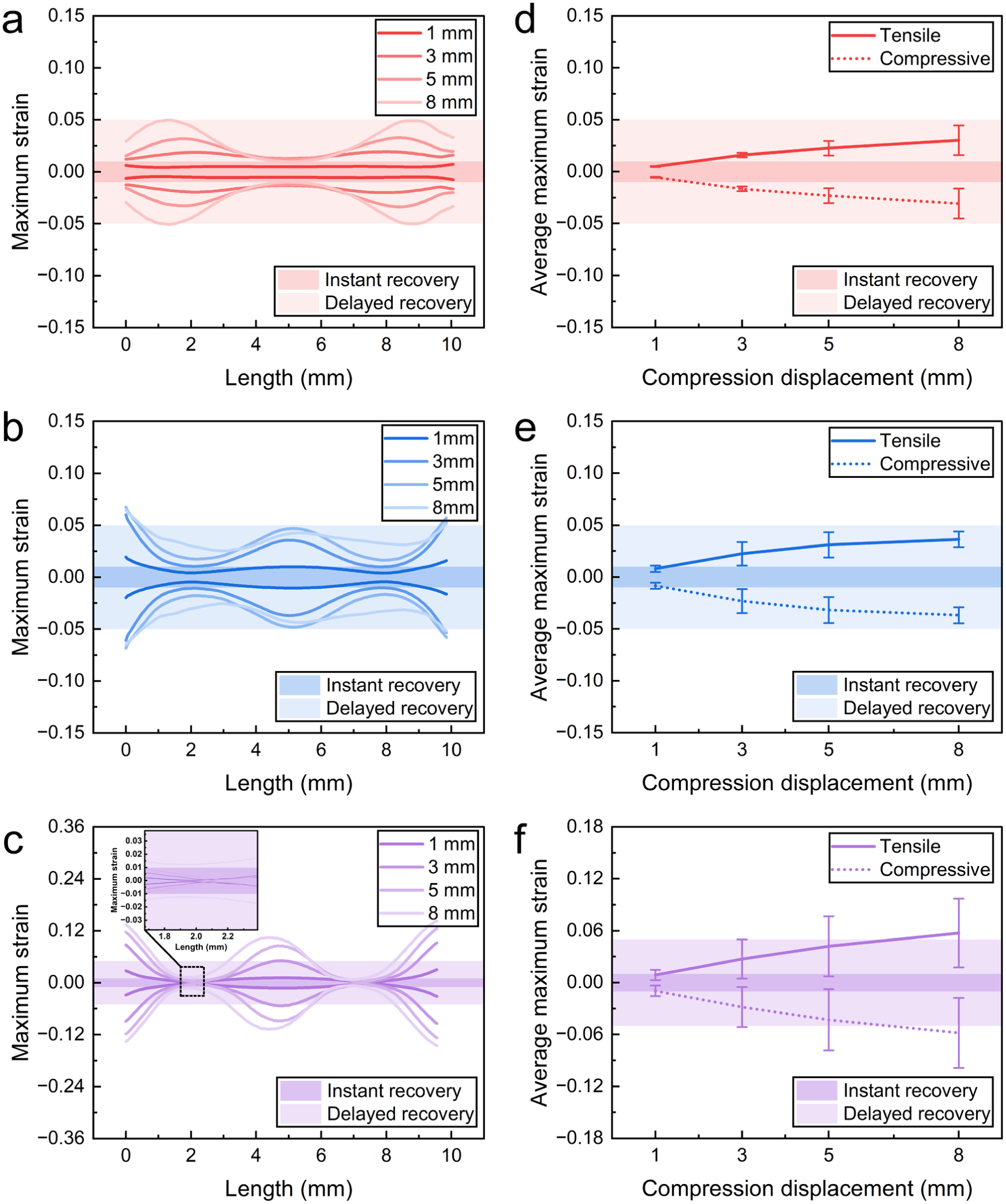
Figure 9 shows the deformation of the monofilaments at different compression depths. From the FE results,
Sectional maximum strain along monofilament length at different compression displacements: (a–c) longitudinal distributions of maximum tensile and compressive strain for (a) i1; (b) i2; (c) v1; (d–f) statistical summary of sectional maximum strains for (d) i1; (e) i2; (f) v1.
Deformation of monofilament at different compression displacements: (a) i1; (b) i2; (c) v1.
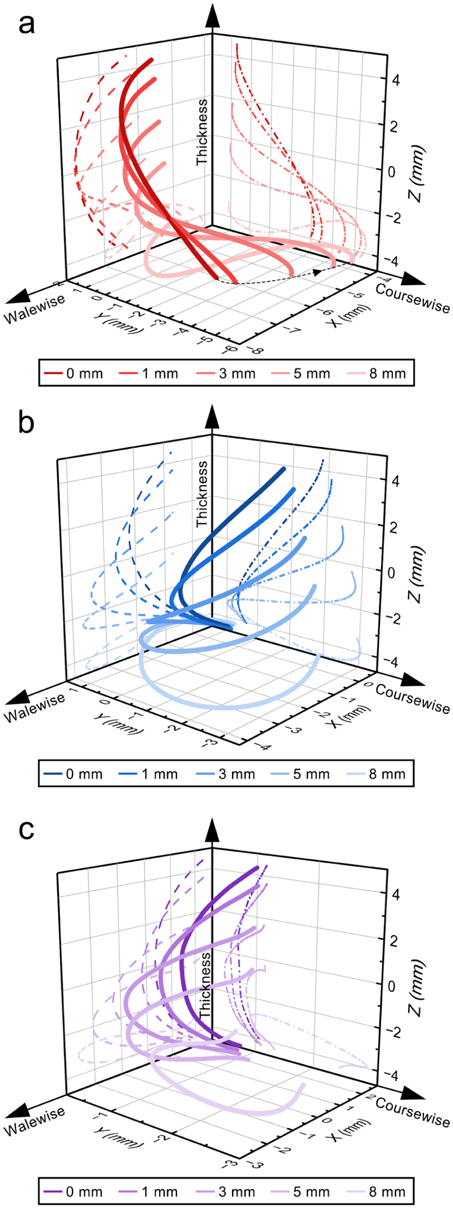
(a–c) Equivalent bending moment of (a) i1; (b) i2; (c) v1. (d–f) Axial force of (d) i1; (e) i2; (f) v1.
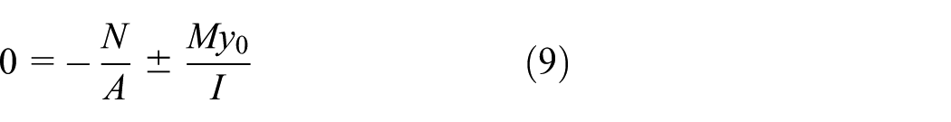
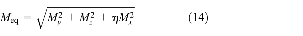
Theoretically, for a beam under combined compression and bending, the maximum normal stress in the cross-section is determined by both axial force
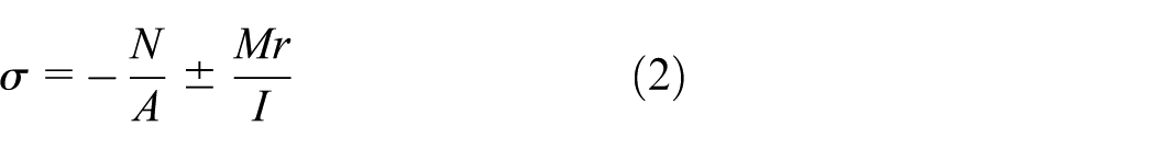
where

At the initial compression stage (1 mm), the bending–axial compression coupling is not yet fully developed, as evidenced by the lack of clear spatial correspondence between equivalent bending moment and axial force. While the axial force follows an approximately parabolic distribution, the bending moment already exhibits distinct spatial variations between the three monofilaments. This indicates that the axial force and bending moment act as independent contributors at this stage. In i1, the bending moment is relatively uniform and small (Figure 10(a)), suggesting limited bending contribution, while the axial force dominates (Figure 10(d)). As a result, the strain distribution remains nearly uniform along the length, with a near-zero standard deviation (Figure 8(d)), and the strain values are mainly within the instant recovery region (≤1%, Figure 8(a)). In contrast, monofilament v1 exhibits localized peaks in bending moment (Figure 10(c)). This localized bending leads to strain concentration near the ends (around the breakpoints), resulting in higher strain levels and entry into the delayed recovery region (≤5%), as shown in Figure 8(c) and (f). Monofilament i2 shows intermediate behavior between i1 and v1. Its bending moment also exhibits localized peaks, though less pronounced than in v1 (Figure 10(b)). Correspondingly, strain concentration begins to emerge, and the strain level lies between those of i1 and v1 (Figure 8(b) and (e)). These results indicate that initial configuration governs strain response: i1 maintains uniform strain, owing to the absence of localized bending, whereas v1 and i2, with localized bending features, exhibit early-stage strain localization and higher strain levels.
As the compression displacement is increased (≥3 mm), the contribution of bending becomes more significant, and the structural response transitions to bending–axial compression coupling. Under large deformation, according to the von Kármán geometric nonlinearity, 29 the axial strain can be expressed as
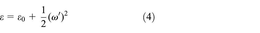
where
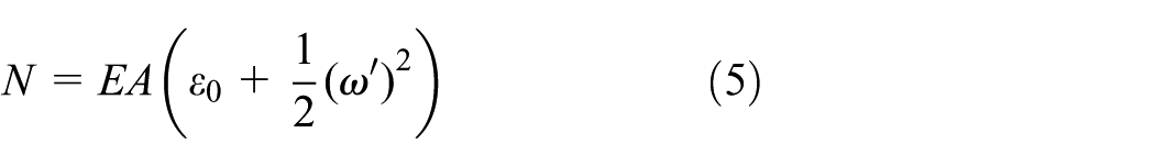
These expressions indicate that axial force and bending moment are coupled through the deflection. Increasing the bending raises the curvature and deflection gradient, introducing an additional axial strain term,
Furthermore, the total shortening of the monofilament can be expressed as
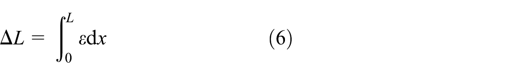
Substituting the strain expression yields
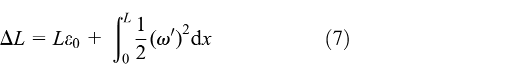
Thus,
This relationship indicates that increased bending reduces the average axial compressive strain
In terms of strain response, both the mean maximum strain and its standard deviation increase, showing increasing strain nonuniformity and concentration. The locations of strain concentration coincide with regions of high bending moment, confirming the dominant role of bending. Distinct differences are observed between the three monofilaments. For i1, the strain level and dispersion remain relatively low, with strain mainly concentrated at the near-end segments (Figure 8(a)) and largely within the delayed recovery region (≤5%), even at 8 mm compression (Figure 8(d)). In contrast, v1 exhibits the highest strain level and dispersion (Figure 8(f)), with pronounced concentration at the mid-span and constrained ends (Figure 8(c)), where irreversible plastic deformation is likely to be initiated. Monofilament i2 shows intermediate behavior, with strain level and dispersion between i1 and v1, and a concentration pattern similar to v1 (Figure 8(b) and (e)).
The strain concentration is governed by the initial geometric configuration, characterized by curvature and torsion, as well as their projections in the coursewise– and walewise–thickness planes. Curvature determines the locations of preferential bending and thus strain localization. Projection controls spatial manifestation: the C-type favors concentration at the mid-span and constrained ends, whereas the S-type promotes concentration at the near-end segments. Torsion regulates the spatial deformation mode and the distribution of bending along the monofilament. For i1, both C- and S-type projections coexist, while higher alternating torsion induces out-of-plane twisting and endpoint displacement (Figure 9(a)), resulting in more distributed deformation and a limited strain range, with peaks mainly at the near-end segments. In contrast, v1, with lower and predominantly unidirectional torsion and C-type projections in both planes, undergoes planar bending (Figure 9(c)), leading to a much larger strain range and concentrated deformation at the mid-span as well as constrained ends. Intermediate configurations (i2) exhibit intermediate characteristics (Figure 9(b)), showing moderate strain range and concentration, lying between i1 and v1.
Overall, increasing fabric compression strengthens bending–axial compression coupling and amplifies these configuration-dependent effects. Initially, strain remains relatively uniform and largely within the instant recovery region under weak coupling. As bending becomes dominant, strain concentration intensifies, governed by the combined effect of curvature magnitude and torsion variation. Higher curvature promotes bending concentration and elevates local strain. Torsion modulates the spatial distribution of deformation. Pronounced torsion facilitates out-of-plane deformation and strain redistribution, reducing peak strain level. Limited torsion favors planar bending and stronger strain localization. Elevated local strain is associated with increased load-bearing response but it accelerates plastic deformation and compromises compression resilience. Therefore, an initial configuration with moderate curvature and torsion (e.g., i2) is preferred. This configuration mitigates excessive strain localization without overly reducing load-bearing capacity.
Radial strain distribution and its governing mechanism
Figure 11(a)–(c) shows the evolution of neutral axis offsets along the monofilament length as compression is increased. For each cross-section, the distance from the neutral axis to the centroid was extracted, and was used to characterize the asymmetry of the radial tensile–compressive strain distribution and its longitudinal variation. Given that PET is more prone to performance degradation under compression than under tension, the area of the compressed region at each cross-section was further calculated. Figure 11(d)–(f) presents the maximum and minimum compressed areas along the monofilament length at different compression depths, highlighting extreme values.
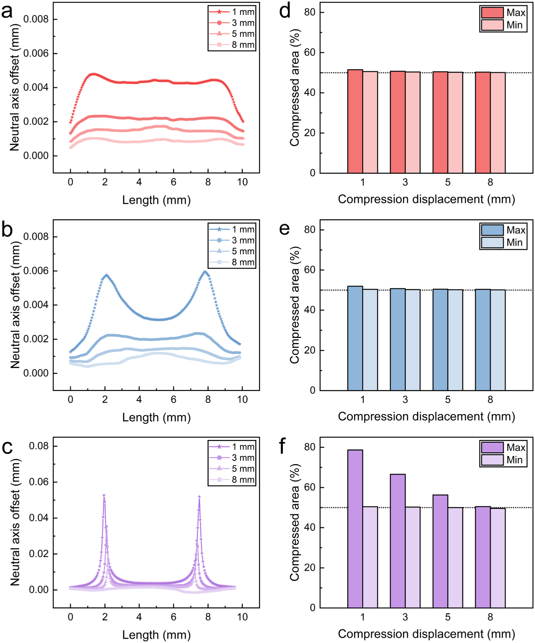
Cross-sectional asymmetric strain distribution along monofilament length at different compression displacements: (a–c) neutral axis offset for (a) i1; (b) i2; (c) v1; (d–f) maximum and minimum cross-sectional compressed areas for (d) i1; (e) i2; (f) v1.
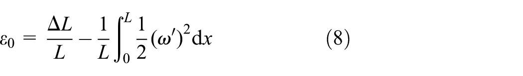
The neutral axis is defined as the location where σ=0. Based on equation (2), denoting the offset of the neutral axis from the centroid as
which yields
For a circular cross-section with diameter
leading to
For a spatial elastic rod:
Based on the extracted axial force
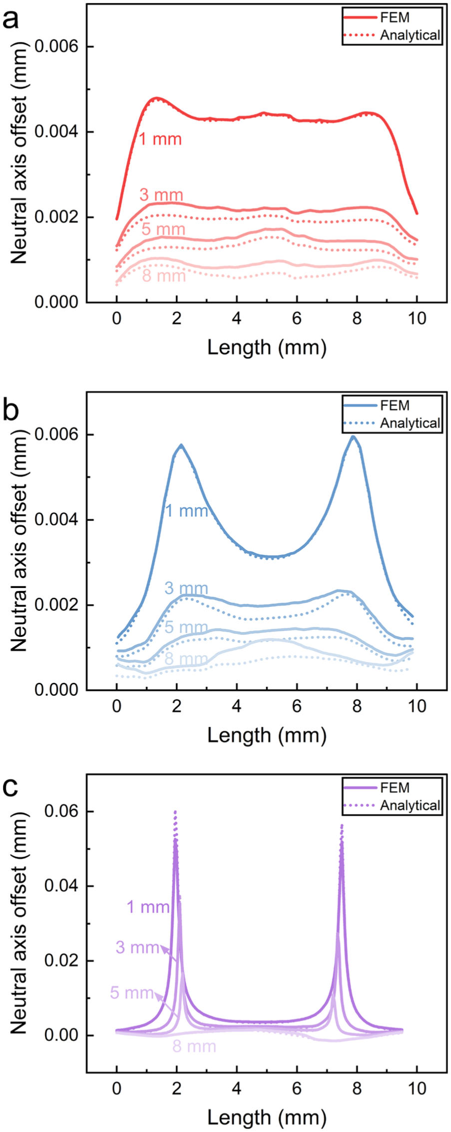
Comparison between theoretical and finite-element neutral axis offset: (a) i1; (b) i2; (c) v1. FEM, finite-element model.
where
The deformation of monofilament v1 is mainly planar (Figure 9(c)). Its response can thus be approximated as a planar bending–axial compression problem, where
Physically, the neutral axis offset is governed by the ratio
At the initial stage (1 mm), as shown in Figure 10, high axial force and low bending moment result in a large
With increasing compression displacement (≥3 mm), the contribution of bending becomes more significant, leading to a reduction in the ratio
Overall, the neutral axis offset reflects the competition between axial force and bending moment
From a mechanical perspective, bending plays a dual role: it promotes longitudinal strain localization while simultaneously reducing cross-sectional compression dominance by lowering
Conclusions
The role of initial configuration in governing the evolution of bending–axial compression coupling and the resulting strain distribution in spacer monofilaments is investigated to inspire resilience improvement. The coupling evolution is clarified, and the strain response along longitudinal and cross-sectional directions is quantitatively characterized. The following conclusions can be drawn.
During the linear elasticity stage, bending–axial compression coupling is weak. The longitudinal strain distribution is relatively uniform, while the cross-sectional tensile–compressive strain distribution is asymmetric. The monofilaments remain largely within the instant recovery region.
As compression progresses into the plateau stage, geometric nonlinearity strengthens bending dominance. Longitudinal strain concentration develops, while the cross-sectional strain distribution evolves toward a more symmetric state. Local parts of the monofilaments enter the delayed recovery region and even develop irreversible deformation.
Longitudinal strain concentration primarily occurs at the mid-span, constrained ends, and near-end segments, governed by monofilament configuration. Curvature governs bending localization, while torsion modulates deformation distribution. Moderate curvature and torsion balance load-bearing capacity and compression resilience.
Radial strain distribution is governed by the competition between axial force and bending moment. Configuration affects the spatial variation of the neutral axis. Damage is dominated by the coexistence of high strain and an approximately 50% compressed area, regardless of configuration. For resilience improvement, the load-bearing capacity and recoverability of this compressed region should be targeted.
Bending plays a dual role in structural response. It induces longitudinal strain concentration and increases strain level, which are associated with the load-bearing capacity, while simultaneously alleviating compression-dominated damage by redistributing cross-sectional strain. The dual effect serves as a key regulating mechanism for compression-sensitive materials. It governs the balance between load-bearing capacity and compression-induced damage.
This study provides insights for improving the resilience of spacer fabrics through configuration and material design. Moderate curvature and torsion can balance load-bearing capacity and resilience; further quantitative analysis is required to identify the optimized configuration. The nearly balanced tensile and compressed regions (about 1:1) at load-bearing cross-sections suggest that bicomponent monofilaments combining tension-resistant and compression-resistant materials may better accommodate a cross-sectionally symmetric mechanical response under large compression, thereby reducing plastic deformation and enhancing durability.
Footnotes
Declaration of conflicting interests
The authors declared no potential conflicts of interest with respect to the research, authorship, and/or publication of this article.
Funding
The authors disclosed receipt of the following financial support for the research, authorship, and/or publication of this article: support by the National Natural Science Foundation of China (grant number 11702062) and the Key R&D Project of Yangzhong City (grant number YE202305).