






Abstract
This paper presents a systematic trajectory generation method for a bipedal robot walking on slopes. A suitable offline walking pattern based on an inverted pendulum model is designed and the planning is parameterized by step lengths, step period and other walking parameters. Meanwhile, a slight unevenness of a slope can cause serious instability for bipedal walking robots. Therefore, this paper also proposes an online control algorithm for a bipedal robot even walking on the unevenness slope, and the robot can adapt to the floor conditions. The control algorithm includes a landing time controller, landing direction controller, zero moment point (ZMP) regulation controller and attitude correction controller. During the process, accurate attitude information for these controllers is achieved through an adaptive filtering method and the ZMP position is measured through force sensing register sensors, which are attached to the robot’s feet. Finally, the experiment is carried out on a SCUT-I humanoid robot. The result proves that the method described in this paper can successfully control a robot walking on slopes.
Introduction
Bipedal robots are more flexible compared with wheeled robots. Many bipedal humanoid robots have been developed, such as WABIAN (Yamaguchi et al., 1998), Asimo (Hirai et al., 1998), HRP (Akachi et al., 2005), KHR (Kim et al., 2007) etc.
Some floors that appear to be flat have local and global inclinations to some degree. Bipedal robots are not very stable during locomotion, so research on how bipedal robots walk on slopes is needed. Some researchers have done some work on this.
Zhou et al. (2004) formulated gait synthesis of humanoid bipedal locomotion as an optimization problem with consideration of some constraints, e.g. zero moment point (ZMP) constraints for dynamically stable locomotion, internal forces constraints for smooth transition and geometric constraints for walking on slopes. Huang et al. (2008) proposed a motion pattern generator for slope walking in 3D dynamics using preview control of a ZMP. Yet these researchers mainly considered offline gait planning of walking on slopes, and feedback controllers are not designed to adapt to the changes in the floor.
Kim et al. (2007) designed a walking control algorithm for a bipedal humanoid robot stably walking on an inclined floor, and the performance of the algorithm was demonstrated in walking experiments using the KHR-2. Suwanratchatamanee et al. (2010) presented a tactile sensing system for humanoid robots walking on slopes autonomously, but how the procedure of bipedal humanoid robots walking on slopes is parameterized and how to fuse and calculate the robot sensor’s data were not mentioned in these papers.
A systematic trajectory generation method is proposed in this paper for a bipedal robot walking on slopes. Firstly, a suitable offline walking pattern based on an inverted pendulum model (IPM) is designed and the planning of a bipedal robot walking on slopes is parameterized. Secondly, an online control algorithm for a bipedal robot walking on slopes is proposed. The robot’s attitude sensors information is fused to improve the accuracy of the robot’s attitude. ZMP position is calculated based on force sensing register (FSR) sensors attached to the sole of the robot’s feet. Finally, the stage of a bipedal robot walking on slopes is divided according to FSR sensors, and some feedback controllers are designed to control bipedal humanoid robots stably walking on slopes. The method of a bipedal robot walking on slopes in this paper is shown in Figure 1.
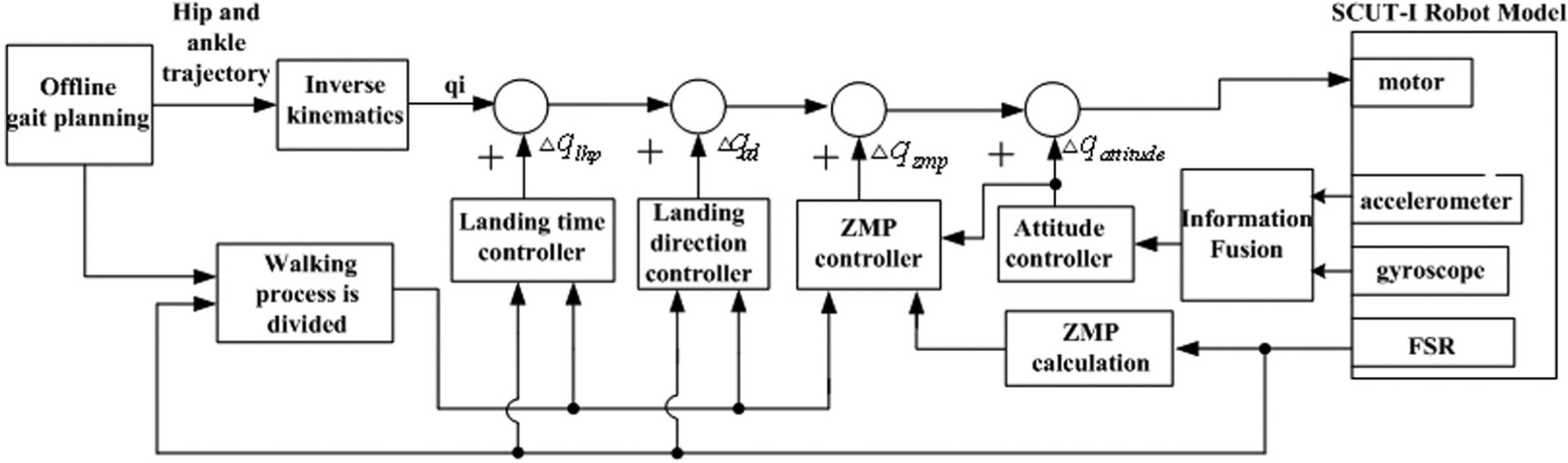
The method of a bipedal robot walking on slopes.
This paper is organized as follows. In the next section, the SCUT-I bipedal humanoid robot, the robot experimental platform, is introduced. Then, an offline gait plan is designed based on IPM (Kajita et al., 2001) in the x- and y-axes, and the gait plan of the robot walking on slopes is parameterized based on some walking parameters. An adaptive filtering method is presented to obtain accurate attitude information and the ZMP position can be calculated based on eight FSR sensors attached to the robot’s feet. Then, the landing time controller, landing direction controller, ZMP regulation controller and attitude correction controller are designed. In this section, the walking process is divided according to the values from the eight FSR sensors and the controller action time that is planned. When the controller is not active, its controller’s parameters are all zero. The performance of the walking control algorithm is assessed and demonstrated through the experiment, and finally, conclusions and the future work are proposed.
Bipedal humanoid robot platform, SCUT-I
The SCUT-I is a bipedal humanoid robot, shown in Figure 2(a). It is used as an experimental platform in this paper. The robot has a height of 582 mm, and only weights 3.9 kg, including batteries. The robot has 21 servo motors: six in each leg, three in each arm, two in the head and one in the trunk. The three-degree-of-freedom (3DoF) orthogonal hip joint and 2DoF orthogonal ankle joint altogether make it possible for the bipedal robot to walk, and the joint in the trunk allows the robot to execute various kinds of movements, such as kicking, goal keeping, getting up from the ground etc.
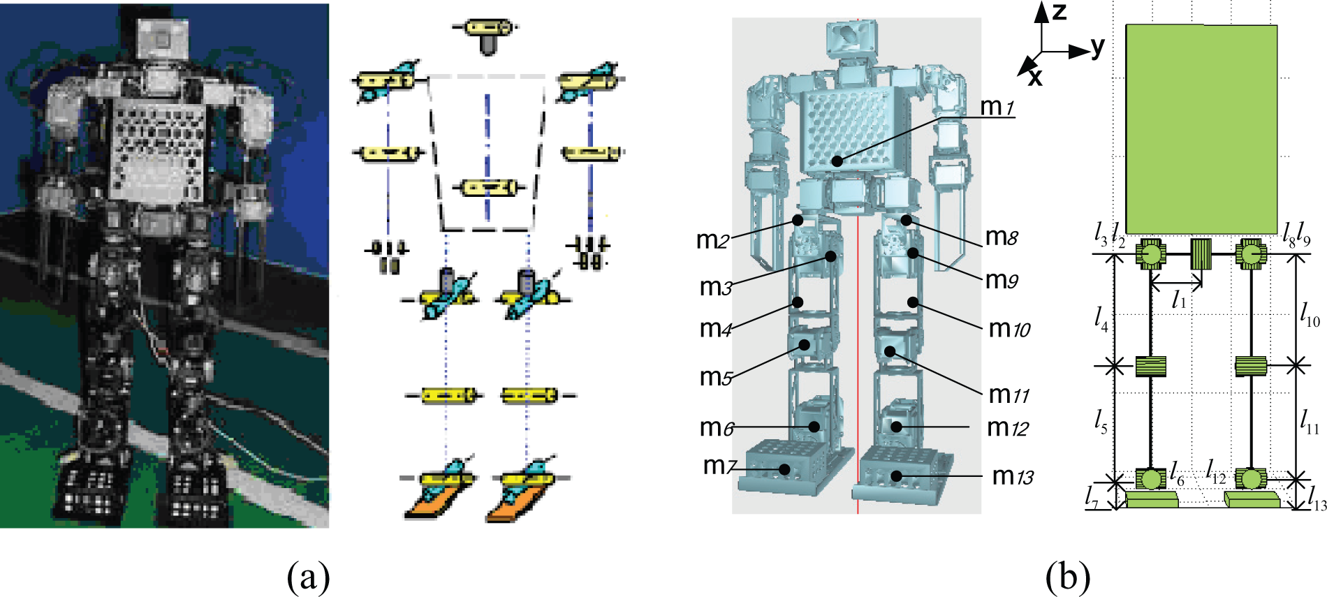
SCUT-I robot and model: (a) SCUT-I robot; (b) SCUT-I robot model.
SCUT-I bipedal humanoid robot model
The robot model is shown in Figure 2(b), in which the arms trajectories are not taken account of, and where m i represents the ith part mass and l i represents the ith part length. The parameters of the robot model are listed in Table 1. The mathematical model of the real SCUT-I bipedal humanoid robot is built. A forward kinematics (FK) mathematic model is based on the screw theory (Kajita, 2005), and an inverse kinematics (IK) mathematic model is based on the geometry relationship in SCUT-I. The robot’s joint angles can be calculated according to the trajectory of hip and ankle.
Structure parameter of SCUT-I biped humanoid robot.

Meanwhile, a ZMP (Vukobratovic, 2004) stability equation of the SCUT-I robot involving momentum, angular momentum, ZMP, velocity and acceleration is established and used as the mathematical basis of bipedal walking stability analysis.
SCUT-I bipedal humanoid robot sensor system
The bipedal robot’s attitude in rolling and pitching directions is needed, which is important to control robot to walk stably. Therefore, attitude sensors need to be mounted on the robot, which can measure the rolling and pitching directions. Acceleration sensor ADXL204 (Analog Device Company, 2006) and gyroscope IDG-300 (InvenSence Device Company, 2007) are mounted at the torso of the SCUT-I robot, as shown in Figure 3(a).
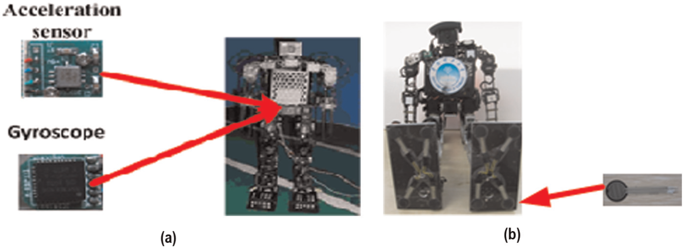
SCUT-I robot sensor system: (a) attitude sensors; (b) force sensing register (FSR) sensor.
It is also important to learn how to obtain the force information of the robot feet during the walking process. In this paper, four FSR sensors are attached to every foot (Figure 3b). So the condition of feet contacting with the ground can be obtained and the ZMP position according to the value of FSR sensors can be calculated.
Offline gait generation of bipedal robot
An offline gait trajectory is firstly designed to make the robot walk. The gait planning of the bipedal robot walking on slopes is parameterized based on step length s, walking cycle
The planning of bipedal robots walking on slopes
The slope-walking gait can be considered a sequence of steps. The walking cycle is composed of two phases: 1) a double-support phase (short for DSP) and 2) a single-support phase (short for SSP).
In DSP, both feet are fixed on slopes. The robot accelerates from standing still, and the centre of gravity (COG) moves in the forward direction. At this time, hip trajectory is designed through a sixth-order polynomial and the ankle trajectory is unchanged.
In SSP, only one foot is stationary on the ground, and the other foot swings from the rear position to the front position. This includes three phases: 1) a rising foot phase, 2) a swinging foot phase and 3) a landing foot phase. At this time, hip trajectory is generated according to the COG trajectory, which is based on IPM in the x- and y-axes, and the ankle trajectory is planned base on the position of the landing point on the ground and sine curve.
The plan of the robot walking on slopes is shown in Figure 4. In the figure, the left leg is the supporting leg and the right leg is the swinging leg from position
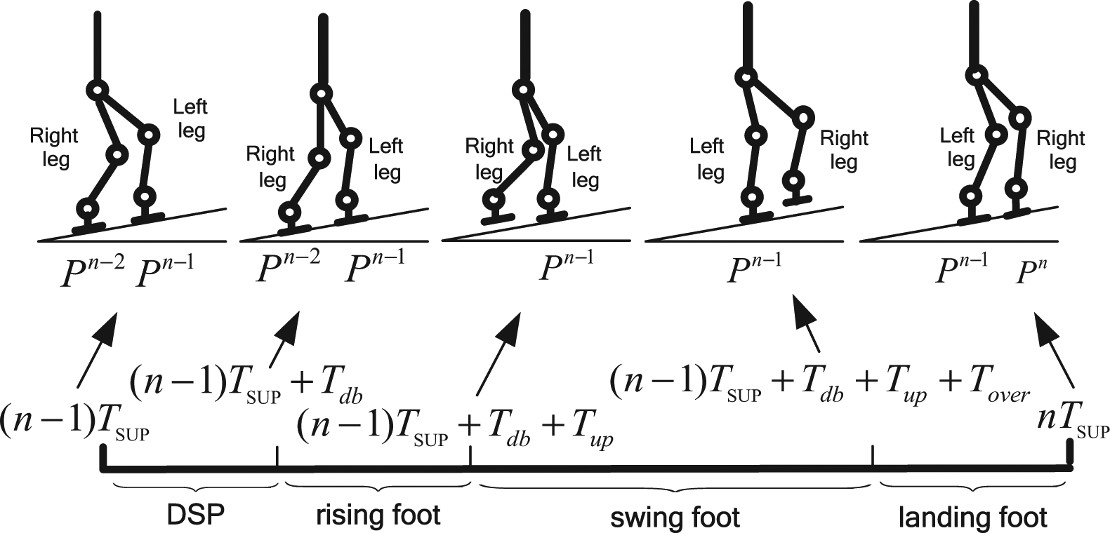
The planning of the robot walking on slopes.
The key points of the cyclical walking period are defined as
According to the plan of the robot walking on slopes, s,

The procedure of the gait planning of the robot walking on slopes is shown in Figure 5.
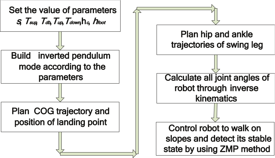
The procedure of the bipedal humanoid robot walking on slopes.
Trajectory generation of the robot walking on slopes
If ankle and hip trajectories of swinging leg are determined, all joint trajectories can be calculated by IK. Therefore, the gait of the robot walking on slopes can be planned through the swinging ankle joint and hip joint trajectory.
A schematic diagram of the robot walking on a slope is shown in Figure 6, where
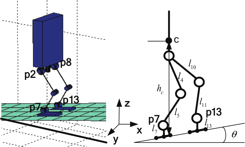
Bipedal humanoid robot walking on a slope.
Hip trajectory of swinging leg
The hip trajectory is generated according to the COG trajectory.

where


Ankle trajectory of swinging leg
The ankle trajectory is planned based on the position of the landing point on the ground. The trajectory in the z-axis is shown by a sine curve. The landing point can be planned according to the walking target position, and adjusted according to the current walking condition (Kajita, 2005). The trajectories in x-, y- and z-axes are shown as follows:


where
Sensors fusion and measurement for the robot walking on slopes
In order to improve the measurement accuracy of robot attitude, a Sage–Husa adaptive Kalman filtering method (Sage and Husa, 1969) is simplified and improved for the system, and an adaptive R is realized. Therefore, the accurate attitude information is achieved. In order to achieve condition of the feet contacting with the ground, four FSR sensors are attached to every foot and the ZMP position can be calculated.
An adaptive filtering method for improving attitude measurement accuracy
The state and observation equation of bipedal robot attitude
The state equation of bipedal robot attitude is shown as follows.

The observation equation is shown as follows.

where
Modified Sage–Husa adaptive Kalman filtering model for bipedal robot attitude
The Sage–Husa adaptive filtering algorithm is an improvement on the traditional Kalman filter. The value of
According to the character of bipedal robot attitude, the mean value of the observation error is r=0 and the mean value of the process error is q=0. So the traditional Sage–Husa adaptive filtering algorithm is simplified. Yet the traditional Sage–Husa algorithm cannot give estimated values when all of the dynamic noises and observation noises are unknown. Moreover, it is apt to be divergent in a high-order system. So it needs to be modified according to the character of the robot attitude.
The observation error covariance matrix
In the practical application, the divergence criterion of filter is designed. It is shown as follows:

When the real error is larger than the ideal error
Calculation of ZMP by FSR sensors
FSR sensors are attached to the robot’s feet, shown in Figure 3(b). The square areas under the feet are labelled during the single-supporting phase and the double-supporting phase respectively, shown in Figure 7. A, B, C and D are the positions of the FSR sensors. FW is the width of robot foot and FL is the length of robot foot.
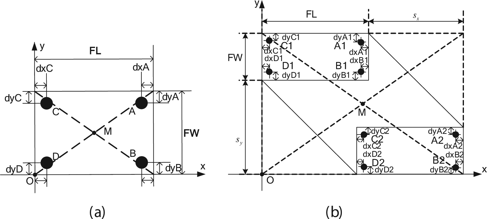
The position force sensing register (FSR) sensor under the feet: (a) single-support phase; (b) double-support phase.
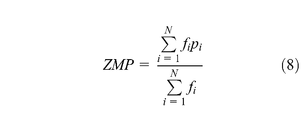
The ZMP position is calculated by Equation (8) according to the value of the FSR sensors.

Online control algorithm
Even a well-designed walking pattern cannot prevent the robot from falling as a result of the large upper body motions, vibrations of the body parts and an uneven floor. Therefore, an online walking control algorithm composed of various online controllers is essential to maintain the dynamic balance in real time. These online controllers can finely compensate for the joint trajectories.
The sensory feedback controller presented in this section consists of a landing time controller, a landing direction controller, a ZMP regulation controller and an attitude correction controller.
The proposed walking control method is based on a controller switching strategy, and thus it is important to divide the walking cycle into several walking phases.
Walking phases and controller action time
According to the offline gait trajectory, the walking cycle is divided into a DSP and an SSP, where the support foot is regarded as in full contact with the ground. Yet during the walking process of a real robot, some area of the support foot often leaves the ground. So the walking phase should be divided more minutely for a real robot. The walking process can be divide into: double-support fully contact phase, double-support not full contact phase, single-support fully contact phase and single-support not full contact phase.
In each walking cycle, suitable online controllers are activated. Figure 8 shows the walking phases and controller action time assignment.
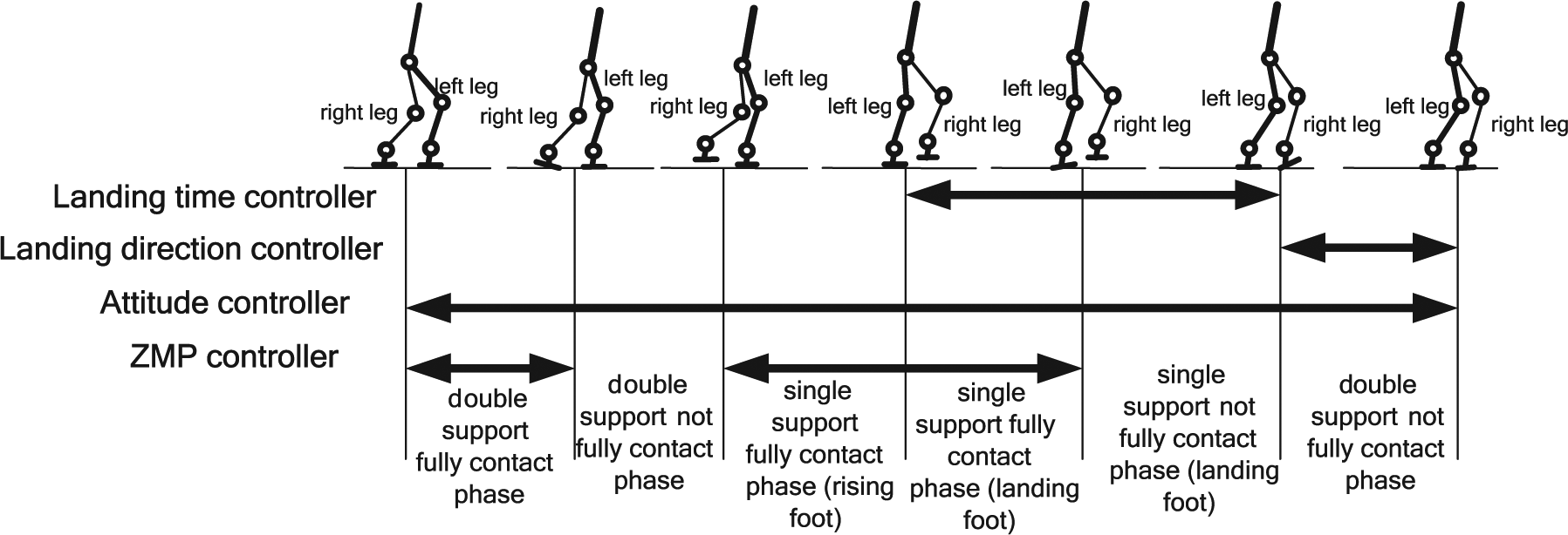
Walking phases and controller action time assignment.
Landing time controller
During the walking process of robots, the landing time of each foot is prescribed by a walking pattern design. Yet when the bipedal robot walks on a slope that is a little uneven, the swinging foot may land earlier or later than the desired landing time, which may cause a large impact force. So it is necessary to design a landing time controller to solve the problem. The landing time controller is designed in Figure 9. The controller is effective during the SSP when the landing swinging foot on the ground.
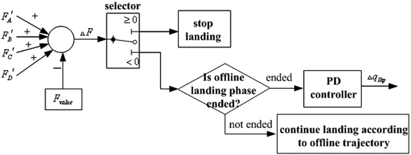
Landing time controller schematic diagram.
When
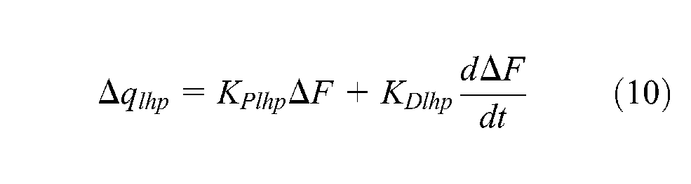
where
According to the SCUT-I robot’s weight,
Landing direction controller
The robot often needs to adjust the direction of its foot to contact fully with the surface when walking on a slope. It is necessary to design a landing direction controller to solve the problem. The landing direction controller is designed in Figure 10. The controller is effective during the double-support not full contact phase.
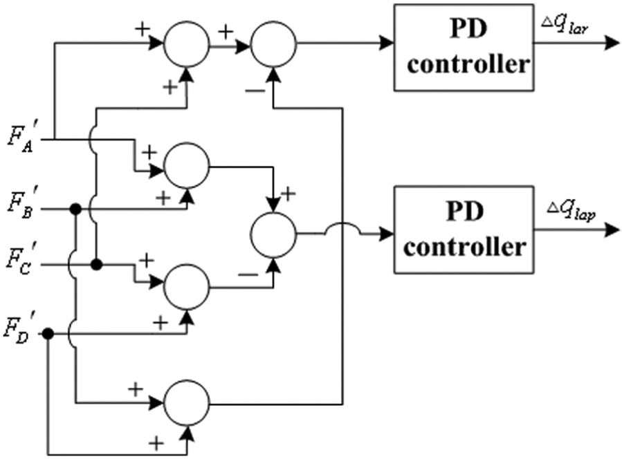
Landing direction controller schematic diagram.
The direction of the foot can be estimated by calculating the difference between the FSR sensors on the swinging foot.
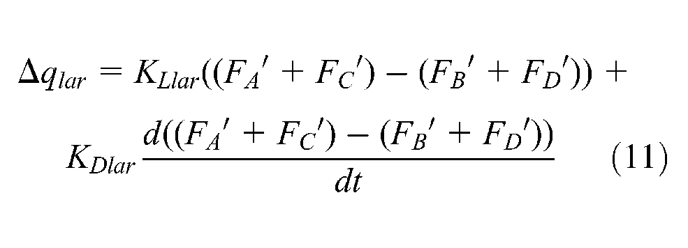
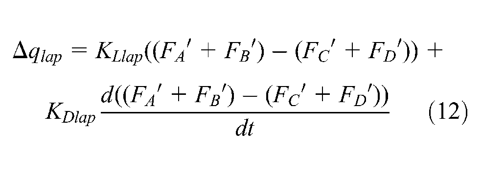
ZMP regulation controller
If the actual ZMP position is controlled within a desired stable region, the robot can maintain stability well. Within a certain range of ZMP, the robot can walk stably. So a non-linear unit
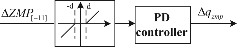
Zero moment point (ZMP) regulation controller schematic diagram.

The
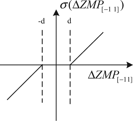
For the SCUT-I bipedal humanoid robot, d=0.6 is selected. The PD controller is described as follows:


Bipedal robot attitude correction controller
In order to make bipedal robot walk on slopes, an attitude correction controller is designed to control the robot body upright all the time through adjusting the angle of the ankle joint in the rolling and pitching directions. The controlled variable

where
Attitude controller in DSP
The attitude control in the rolling direction is shown in Figure 13(a). The attitude controller superimposes the control input of the PD controller using the torso roll error
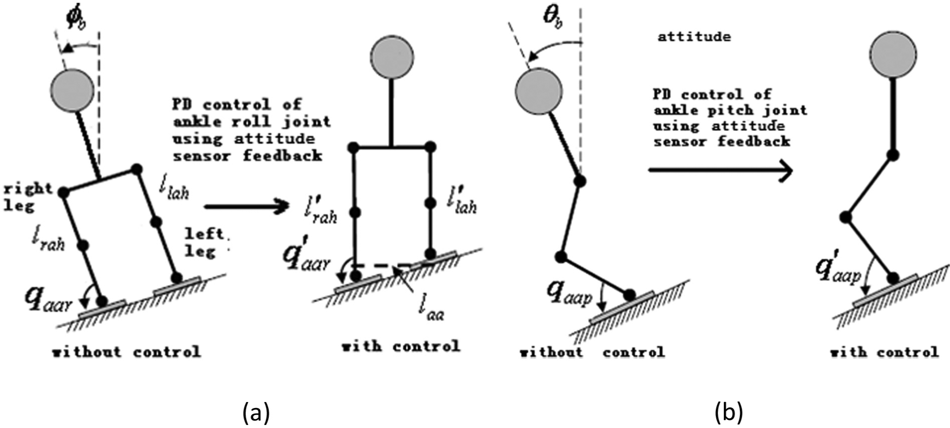
Attitude control explain drawing: (a) attitude control in rolling direction; (b) attitude control in pitching direction.
The equation of rolling direction controller is shown as follows:

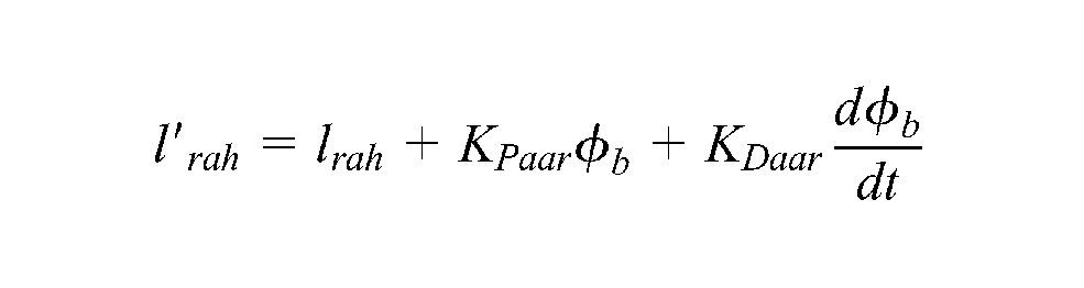

where
The attitude control in the pitching direction is shown in Figure 13(b). The attitude controller also superimposes the control input of the PD controller using the torso pitch error
The equation of pitching direction controller is shown as follows:
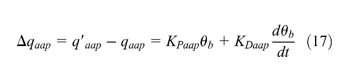
where
Attitude controller in SSP
The attitude controller also superimposes the control input of the PD controller using the torso rolling error
The equation of the controller in the SSP is shown as follows.
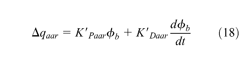
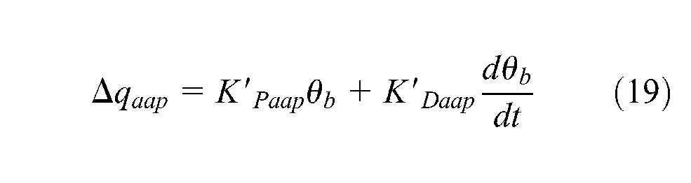
where
Experimental simulation and result
Simulation of offline gait planning
According to SCUT-I robot model, a simulation of bipedal humanoid robot walking on slopes is constructed using Matlab 6.5. A slope model is built with a slope angle of 6°.
The parameters are given according to the restriction condition and listed in Table 2. The COG initial co-ordinates are
The parameters for walking on slopes.

According to the planning method mentioned in this paper, the robot successfully walked on the slope in simulations, shown in Figure 14(a), and the curves of swinging ankle and hip are shown in Figure 14(b) and (c).
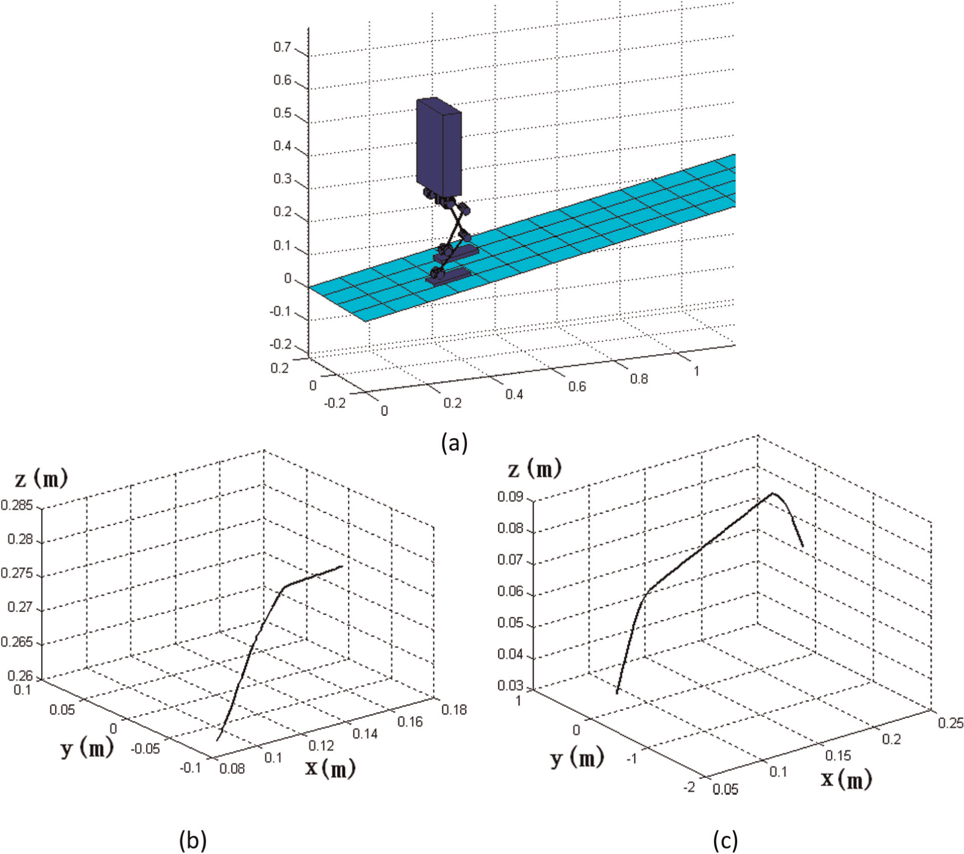
The simulation of robot walking on slopes by using Matlab 6.5: (a) successfully walking on the slope; (b) the curve of swinging hip; (c) the curve of swinging ankle.
During the walking on slopes process of the robots, the ZMP position can be calculated, and
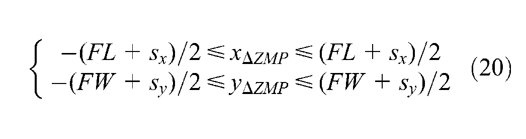
In the SSP,
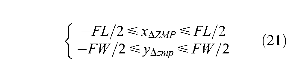
and FL=0.14 m and FW=0.08 m. So in the DSP,
During the walking on slopes process of the robots, the curve of
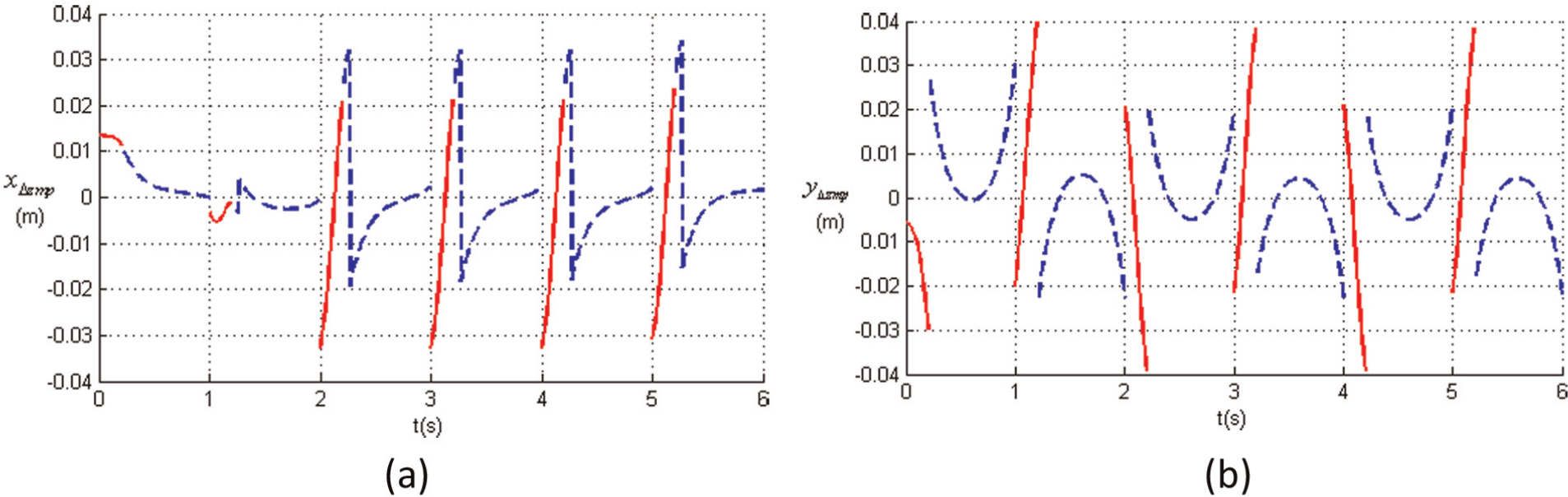
The curve of
After the curve is analysed according to Equations (20) and (21), the offline gait trajectory method mentioned in this paper is proved to be effective in that offline gait planning can make the robot stably walk on the slope.
SCUT-I robot walking on a slope
The SCUT-I bipedal humanoid robot is controlled to walk on a slope whose inclination angle is 6°, as shown in Figure 16.
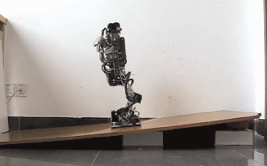
SCUT-I robot walking on a slope.
The slope in Figure 16 is supported by two boxes, and the middle of the slope is uneven. So with only an offline gait planning method, it is difficult to make the robot stably walk on the slope.
The online control algorithm that mentioned in this paper is required to be used. By using this method, the SCUT-I robot was controlled to walk on the slope stably and successfully, as shown in Figure 17.
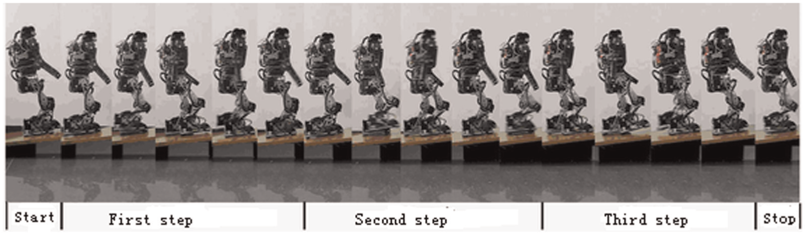
SCUT-I robot walking on a slope successfully.
The curve of attitude fusion result is shown in Figure 18, where the attitude of robot is controlled at ±7° when the robot walked on the slope. During the process, the attitude correction controller is effective in making the robot hold a certain attitude in order to make walk stably on the slope.
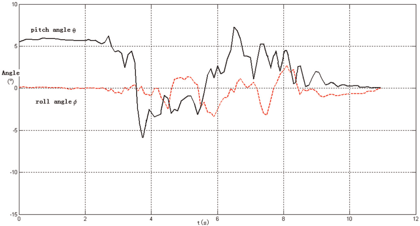
The curve of attitude result when the robot walked on the slope.
The curve of
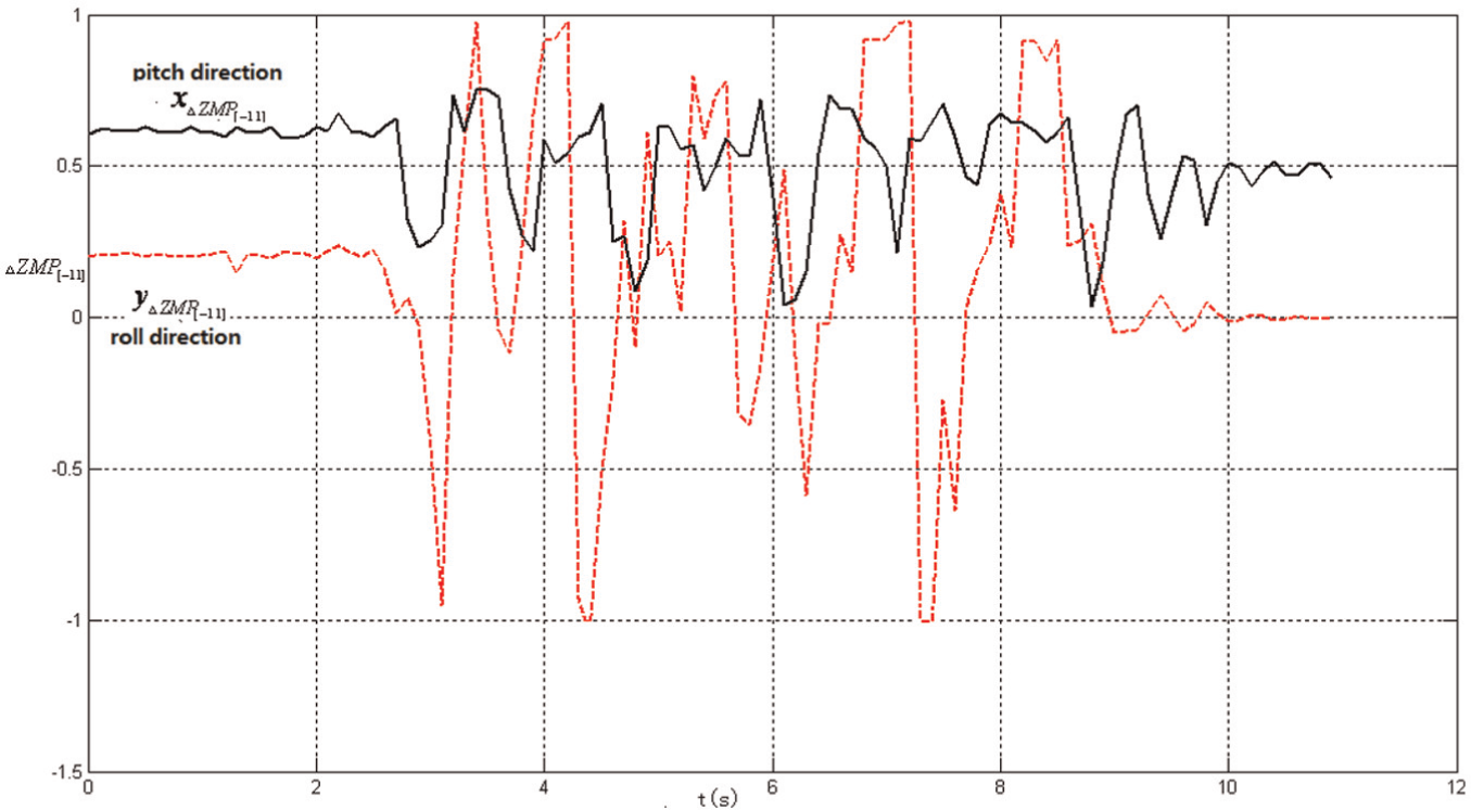
The curve of
When the robot’s walking state is in a full contact phase, the ZMP regulation controller is effective and controls
Conclusions
This paper presents a systematic trajectory generation method for a bipedal robot walking on slopes. The planning of robots walking on slopes is parameterized according to the slope environment. A suitable hip and ankle trajectory are designed based on an IPM. Besides offline gait planning, a landing time controller, landing direction controller, ZMP regulation controller and attitude correction controller are designed to control the SCUT-I robot walking on slopes. During the process, an accurate robot attitude, ZMP position and FSR measurement value are needed. In order to obtain accurate attitude information, an adaptive filtering method is built for the fusion of acceleration and gyroscope sensors based on the Sage–Husa adaptive Kalman filtering method. It is simplified and improved for robot attitude measurement in which the measurement noise covariance
In the future, some methods can be used to optimize the parameters so that the bipedal robot can walk more stably and more quickly.
Footnotes
Funding
This research is supported by Guangdong Provincial Funds (No. S2011040002784) and Central University of Basic Scientific Research Funds (No. 2011ZM0067 and No. 2011ZM0065). Guangdong Ministry of Education Foundation (No. 2011B090400590).