






Abstract
To achieve the radial displacement self-sensing detection of a bearingless induction motor, an observation method based on the LS-SVM (least squares support vector machine) is proposed. The state-space model of a magnetic suspension system is derived firstly. Then the LS-SVM is introduced to the radial displacement observer of the bearingless induction motor, the design principle and Lyapunov stability of the LS-SVM displacement observer are analysed in detail, and the construction method of the LS-SVM displacement observer is presented also. Simulation and verification results show that both in the starting suspension stage and in the process of stable suspension operation, the LS-SVM displacement observer can quickly track the radial displacement with high accuracy. Then, a new method is found for the radial displacement self-sensing detection of the bearingless induction motor.
Keywords
Introduction
The conventional alternating current (AC) motor supported by a mechanical bearing is widely used in various industrial fields (Sun et al., 2013; Sun et al., 2014), but it is difficult to meet the requirement of long-time and high-speed running (Bu et al., 2015; Sun et al., 2012); then, a motor supported by magnetic bearings was developed (Kim et al., 2014), but it still has some disadvantages, such as more magnetic suspensions cost, over speed difficulty and limited critical speed (Bu et al., 2009; Chiba and Santisteban, 2012; Huang et al., 2014; Wang et al., 2015). Based on the comparability in structure between the magnetic bearing and common AC motor, a bearingless motor is proposed. The bearingless motor is a new type of AC motor that is suitable for high-speed and long-time operation (Bu et al., 2014a, 2014b; Sun et al., 2013). Compared with the motor supported by a magnetic bearing, the bearingless motor has a series of advantages, such as shorter rotor shaft, higher critical speed and lower magnetic suspensions cost (Bu et al., 2014b; Chiba and Santisteban, 2012), and has become a new research hotspot. However, the magnetic suspension system of the bearingless motor has a negative displacement stiffness coefficient, so it is unstable. To stabilize the stable suspension control of the rotor, it is necessary that the radial displacement of the rotor should be detected in real time, and negative feedback control should be introduced. An eddy current sensor can be used to detect the radial displacement of the rotor, but the displacement sensor occupies a certain shaft length, and then limits the improvement of critical speed to a certain degree. In addition, the high cost of the displacement sensor greatly increases the cost of the control system. Therefore, the self-sensing observation technology of radial displacement has become a key problem of the bearingless motor in popularization and application.
The position tracking control of the common AC motor has been widely covered in the literature (Ha et al., 2015; Xia et al., 2005). Meanwhile, the radial displacement observation of the bearingless motor is an ongoing research topic. Based on the approximate linear relationship between the radial displacement of the rotor and the self-inductance of suspension windings, a high-frequency excitation signal is injected into the suspension windings of the bearingless induction motor by Tera et al. (2005), and by detecting the differential voltage variation of suspension windings, the radial displacement components are extracted. When the rotor deviates from the stator centre, the mutual inductance coupling between torque windings and suspension windings is generated; based on the mutual inductance coupling relationship, a high-frequency excitation signal is injected into the torque windings of a bearingless induction motor by Kuwajima et al. (2001), and the induced current in suspension windings is detected. After a series of signal processing, the radial displacement components of the rotor are extracted. The two methods are not affected by the fundamental physical phenomenon and are not sensitive to the parameters of the bearingless motor and of strong detection robustness; however, they require sustained high-frequency excitation, and depend on the complex signal processing technology, and then have difficulty in implementation. When the rotor deviates from the stator centre of the bearingless permanent magnet (PM) motor, based on the mutual inductance coupling relationship between torque windings and suspension windings, and by calculating in real time the coupling flux linkage of torque winding to suspension winding, Bai et al. (2009) proposed a displacement estimation method; this method does not need a high-frequency excitation signal, and is easy to realize; however, the accuracy of the mutual inductance parameter directly influences the observation precision of radial displacement. Then, how to overcome the influence of the motor parameter on the observation performance by machine learning theory is still a problem to be further studied. Based on the neural network, Xia et al. (2005) try to design the position observer of the switched reluctance motor and a better observation effect is obtained; however, some problems of the neural network itself, such as slower convergence rate, easily falling into local minima and greater dependence of network structure design on expert experience, limit the application range of the presented method. The support vector machine (SVM) is a new machine learning method based on statistical learning theory (Vapnik, 1999); it can minimize the dependence of the neural network on experience knowledge, and has some outstanding characteristics, such as small sample learning, stronger generalization ability, global optimization ability and fixed topological structure. The stronger self-learning ability and generalization ability of the SVM facilitate the motor model identification and parameter estimation. The LS-SVM, that is, the least squares SVM, is a further expansion of the conventional SVM (Suykens, 1999, 2001); it changes the inequality constraint of the SVM to equality constraint, and switches the problem of solving quadratic programming to that of solving a linear equation, effectively simplifying the complex computation process, and then makes the LS-SVM applicable to the modelling and control of the bearingless motor (Sun et al., 2012). Based on the model analysis of the magnetic suspension switched reluctance motor (Zhu et al., 2012), the estimation method of displacement and position are investigated based on the LS-SVM. Based on the regression theory of the relevance vector machine (RVM), Xiang et al. (2013) constructs the forecasting model of a magnetic suspension switched reluctance motor, and then the radial displacement is estimated based on the generalization ability of the RVM. When machine learning is used to detect motor parameters, the uncertainty and nonlinearity of the system can be effectively solved, and then an effective way of thinking has been provided to observe the displacement of the bearingless motor.
In this article, a new displacement observation method is presented for a bearingless induction motor. On the basis of existing researches, the LS-SVM is first introduced to the displacement observer of the bearingless induction motor. That is, the LS-SVM is used to approximate the nonlinear state-space characteristics of the magnetic suspension system, and then the radial displacement components of the bearingless induction motor are estimated.
Magnetic suspension system modelling of the bearingless induction motor
Working principle of the bearingless motor
From the electromagnetic field theory, the Maxwell electromagnetic force is generated on the interface between the motor iron core and air gap, and it is approximately vertical to the interface (Bu et al., 2009). When the air gap flux density is distributed symmetrically, the resultant radial force that acts on the rotor equals zero. However, when the rotor deviates from stator centre, the symmetric distribution of the air gap magnetic field is broken, and the resultant radial force does not equal zero again. The resultant radial force is entitled unilateral magnetic pull, which influences the stable suspension of the rotor. To achieve stable suspension of the rotor, it is necessary to produce a controllable radial force to counteract the unilateral magnetic pull and external radial load.
In the bearingless motor, there are two sets of windings in stator slots, namely torque windings and suspension control windings. Torque windings are the conventional AC motor windings, where the number of pole pairs is P1 and the electrical angle frequency of current is ω1. The suspension control windings are used to produce an additional suspension control magnetic field, where the number of pole pairs is P2 and the electrical angle frequency of current is ω2. When the suspension control magnetic field is superimposed on the original rotating magnetic field of the AC motor, the balance and symmetry of the air gap magnetic field is broken, the air gap magnetic field in some air gap area is enhanced and that the space symmetric area is weakened; then an additional radial force is produced in the enhancement direction of air gap magnetic field. When the two sets of windings meet the condition of “P2 = P1± 1, ω2 = ω1”, the produced additional radial force is controllable both in amplitude and in direction (Bu et al., 2009). The controllable radial force is the so-called controllable magnetic suspension force, which can be used to counteract the unilateral magnetic pull and external radial load, and to achieve stable suspension of the rotor.
Definition: αβ is the stationary coordinate system in mechanical space. Then, taking the four-pole bearingless motor with two-pole suspension control windings as an example, Figure 1 shows the generation principle of controllable magnetic suspension force. In Figure 1, Na and Nb represent four-pole torque windings, that is, four-pole motor windings; Nα and Nβ represent two-pole suspension control windings. At the moment that stator currents of the two sets of windings are as shown in Figure 1, the controllable magnetic suspension force along the β direction is produced. If the current direction of the suspension control windings is reversed, the controllable magnetic suspension force would be produced along the opposite β direction. The generation principle of controllable magnetic suspension force along the α direction is similar.
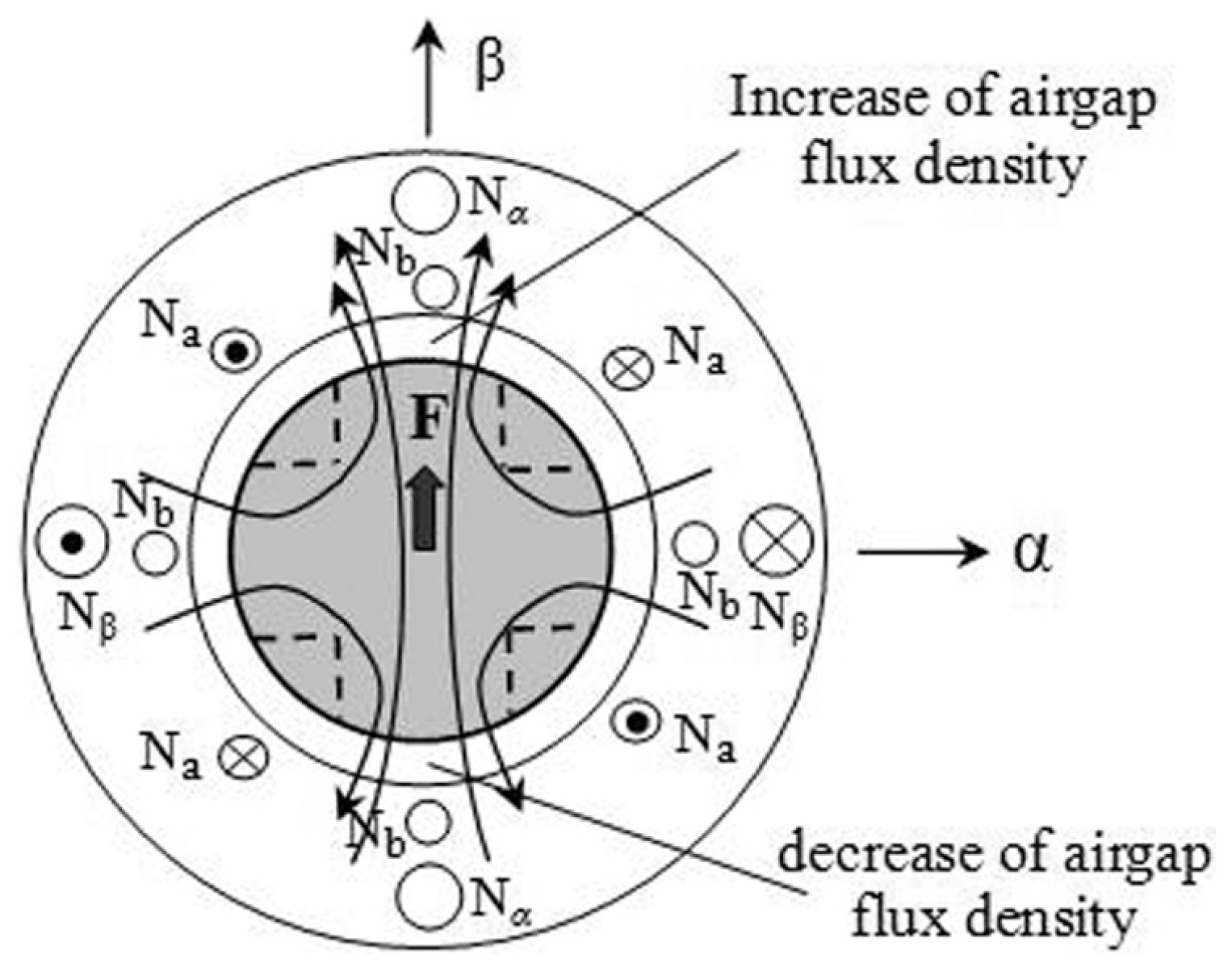
Schematic diagram of controllable magnetic suspension force.
State-space model of the magnetic suspension system
Definition: dq is the synchronous coordinate system oriented by the rotor flux-linkage of the torque system. Then, according to the working principle of the bearingless induction motor, the mathematical model of controllable magnetic suspension force can be derived as follows (Bu et al., 2014b; Chiba and Santisteban, 2012):
In (1), Fα and Fβ are the controllable magnetic suspension force components along the α and β directions, respectively; is2d and is2q are the current components of suspension control windings along the d and q coordinate axes, respectively; ψ1d and ψ1q are the air gap flux-linkage components of torque system along the d and q coordinate axes, respectively.
According to (1), it is clear that the controllable magnetic suspension force has a direct relationship with the air gap flux-linkage of torque system. According to the relationship between the air gap flux-linkage and rotor flux-linkage, the components ψ1d and ψ1q can be calculated in real time. The expressions of ψ1d and ψ1q are as follows (Bu et al., 2014a):
Based on the mechanical dynamics principles, and ignoring the unbalanced exciting force caused by rotor mass eccentricity, the suspension motion equation of the rotor can be defined as follows:
In (3), m is the mass of the rotor;
By substituting (1) and (2) into (3), the suspension motion equation of the rotor is rewritten as follows:
Definition: the input variables u, the state variables x and the output variables y of the magnetic suspension system are as follows:
Assuming ut1 and ut2 as input components of the magnetic suspension system, the expressions of ut1 and ut2 are as follows:
Meanwhile, by substituting (5) and (6) into (4), the state-space model of the magnetic suspension system can be derived as follows:
where
According to (7), it is clear that if ut1 and ut2 are seen as independent input components, the magnetic suspension system is a linear system whose state variables x are observable, and the displacement components α and β can be estimated according to relevant state variables. Then, the observation problem of radial displacement can be transformed into that of state variables x.
Least squares support vector machine displacement observer
Design principle of the LS-SVM displacement observer
According to (6), ut1 and ut2 are not independent inputs, and they are nonlinear functions of u1, u2, u3, u4 and u5. That is, the actual magnetic suspension system is nonlinear, and then the displacement observer cannot be designed simply by linear system theory.
Rewrite (7) as follows:
where
In the state-space model of magnetic suspension system as shown in (8), the function vector
Figure 2 shows the designed topological structure of the LS-SVM; the principle and derivation process of the LS-SVM are described in related literature (Suykens and Vandewelle, 1999; Syukens et al., 2001), and will not be detailed here. From Figure 2, it is clear that the topological structure of the LS-SVM is similar to that of the three-layer neural network.
In (12), N is the training sample number; i is the serial number of the training sample, i = 1, 2, 3, …, N; j is the serial number of the LS-SVM learning machine, j = 1, 2, 3, 4;
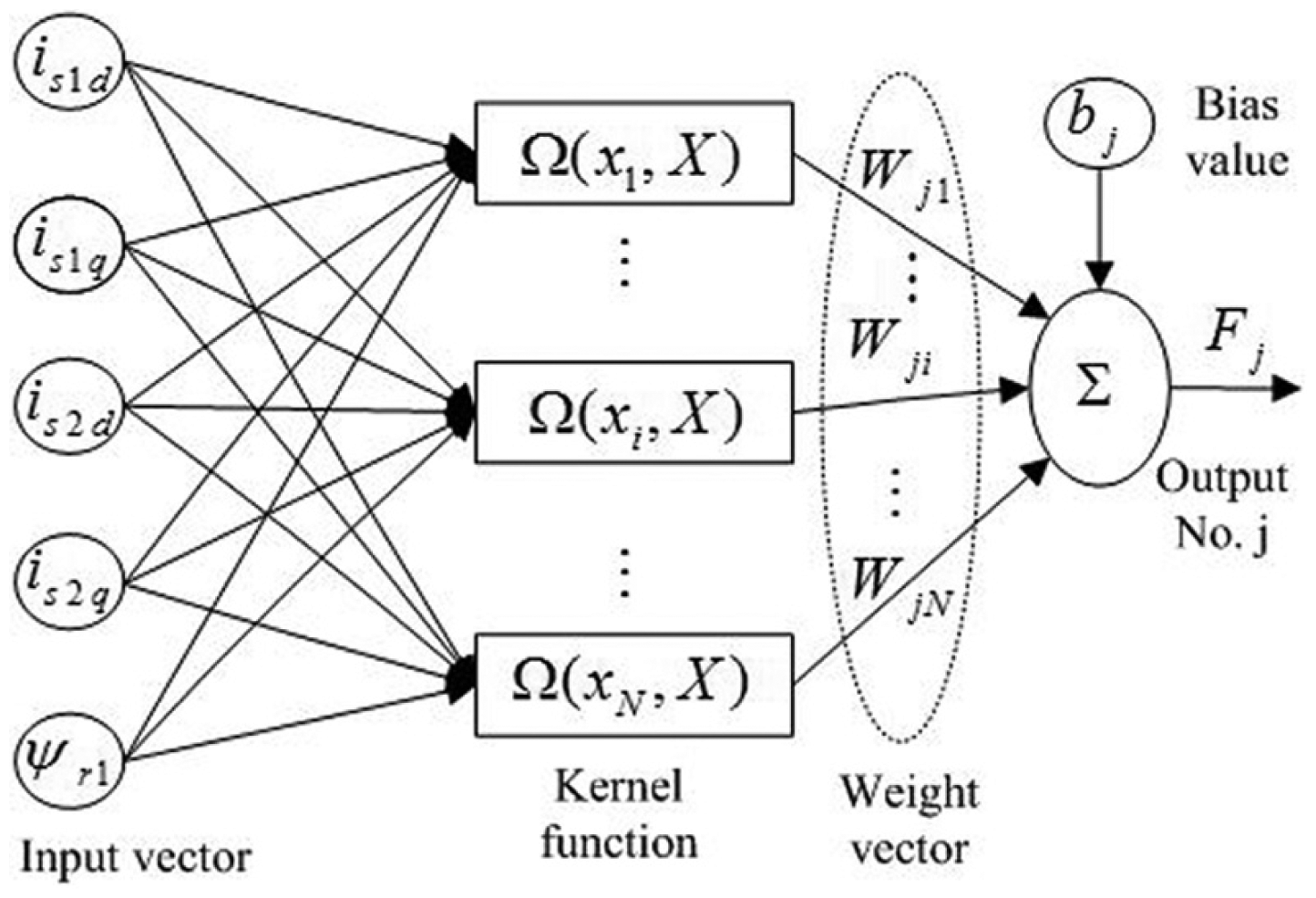
Topological structure of the least squares support vector machine.
Rewrite (12) in a matrix form:
In (13), W is the weight coefficient matrix and
On the condition of ignoring the approximation error of the LS-SVM, where W is a constant matrix trained by the LS-SVM, the nonlinear system described by (8) is equivalent to the following:
Then the observer designed for (8) can be transformed to that designed for (16); the designed observer can be expressed as follows:
where K is a constant value gain matrix that makes “
After the difference between (16) and (17) is taken into account, the dynamic equation of state estimation error
Stability analysis of the LS-SVM displacement observer
Select the Lyapunov function as follows:
where P is the positive definite solution of the Lyapunov equation “
After taking the derivative for the Lyapunov function V, we get the following:
From (20), it can be seen that
Realization of the LS-SVM displacement observer
To realize the LS-SVM displacement observer, the offline training and fitting of function vector
The first step is the collection of a training sample. In this article, the training samples are obtained from the analytical inverse control system of the bearingless induction motor (Bu et al., 2014a). In the practical operation range, adopting the normal distribution random signal as input, it continues for 2 s, and the sampling period is 1 ms. During the sampling period, some signals are sampled, including
The second step is offline training for the LS-SVM. Using
The third step is to construct a LS-SVM displacement observer. Based on the trained LS-SVM model and (17), the displacement observer is designed as shown in Figure 3. When the observed displacement deviates from the actual value, the differential quantity of observation error
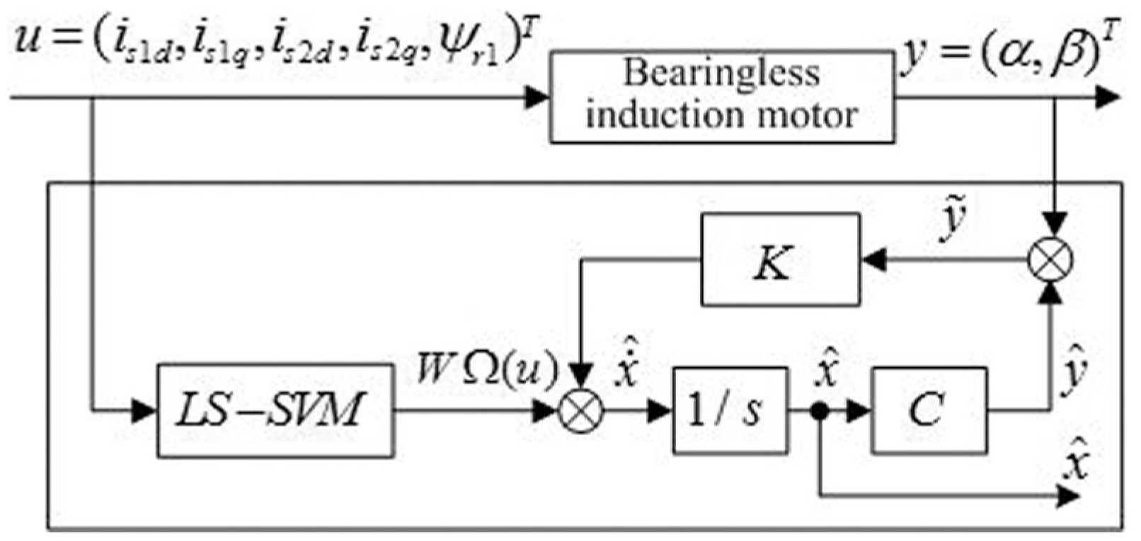
Structure diagram of the least squares support vector machine displacement observer.
Simulation verification and analysis
To verify the validity of the proposed LS-SVM displacement observer, the control system of the bearingless induction motor is constructed as shown in Figure 4. Based on MATLAB/Simulink, the proposed displacement observer is simulated and analysed.
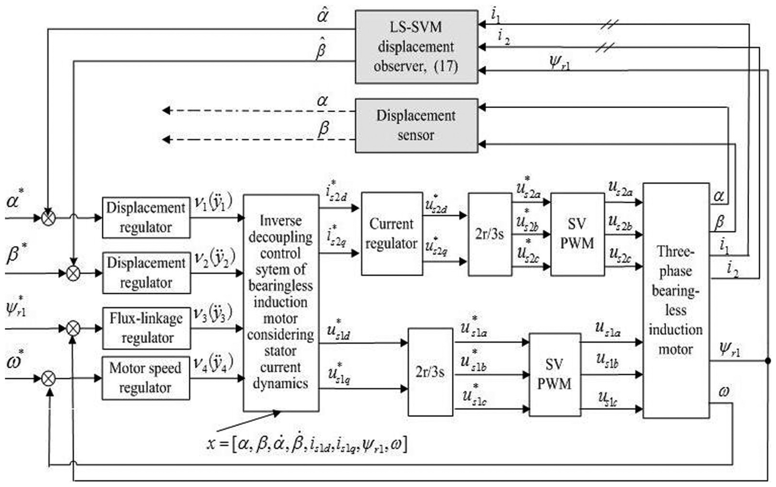
Control system of the bearingless induction motor-based least squares support vector machine (LS-SVM) displacement observer.
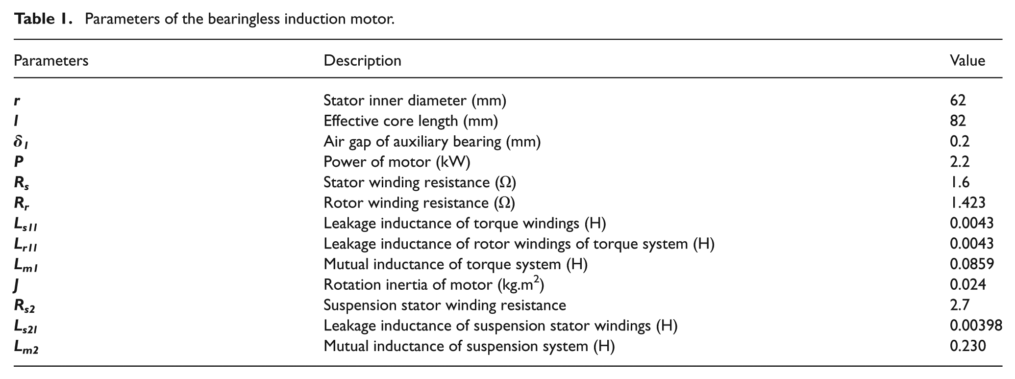
In Figure 4, the control system structure is designed based on inverse dynamic decoupling control strategy (Bu et al., 2014a); due to the limit of paper length, it will not be introduced in detail. The parameters of the bearingless induction motor are listed in Table 1.
Parameters of the bearingless induction motor.
To validate the observation performance of the proposed LS-SVM displacement observer, we set the initial radial displacement of the bearingless induction motor as follows: α = −0.1 mm, β = −0.12 mm; on the conditions of adopting displacement sensor, the bearingless induction motor is started running at no-load. During the process from start suspension to stable suspension, the contrast response curves between the displacement sensor and the LS-SVM displacement observer are shown in Figures 5 and 6. In order to view the tracking accuracy of radial displacement more clearly, the displacement tracking error curves in Figures 5 and 6 have been enlarged.
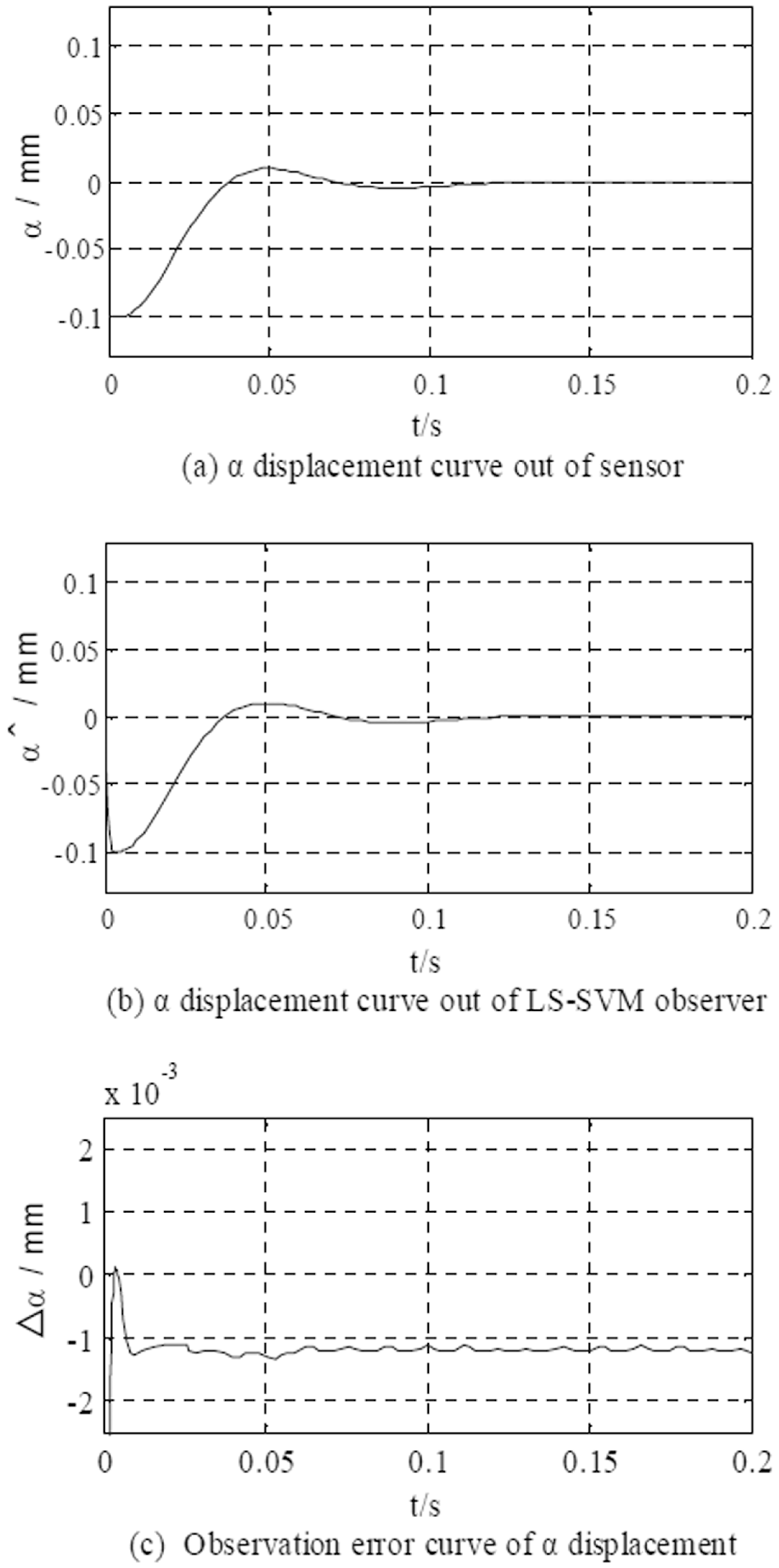
α displacement curves during starting suspension. LS-SVM: least squares support vector machine.
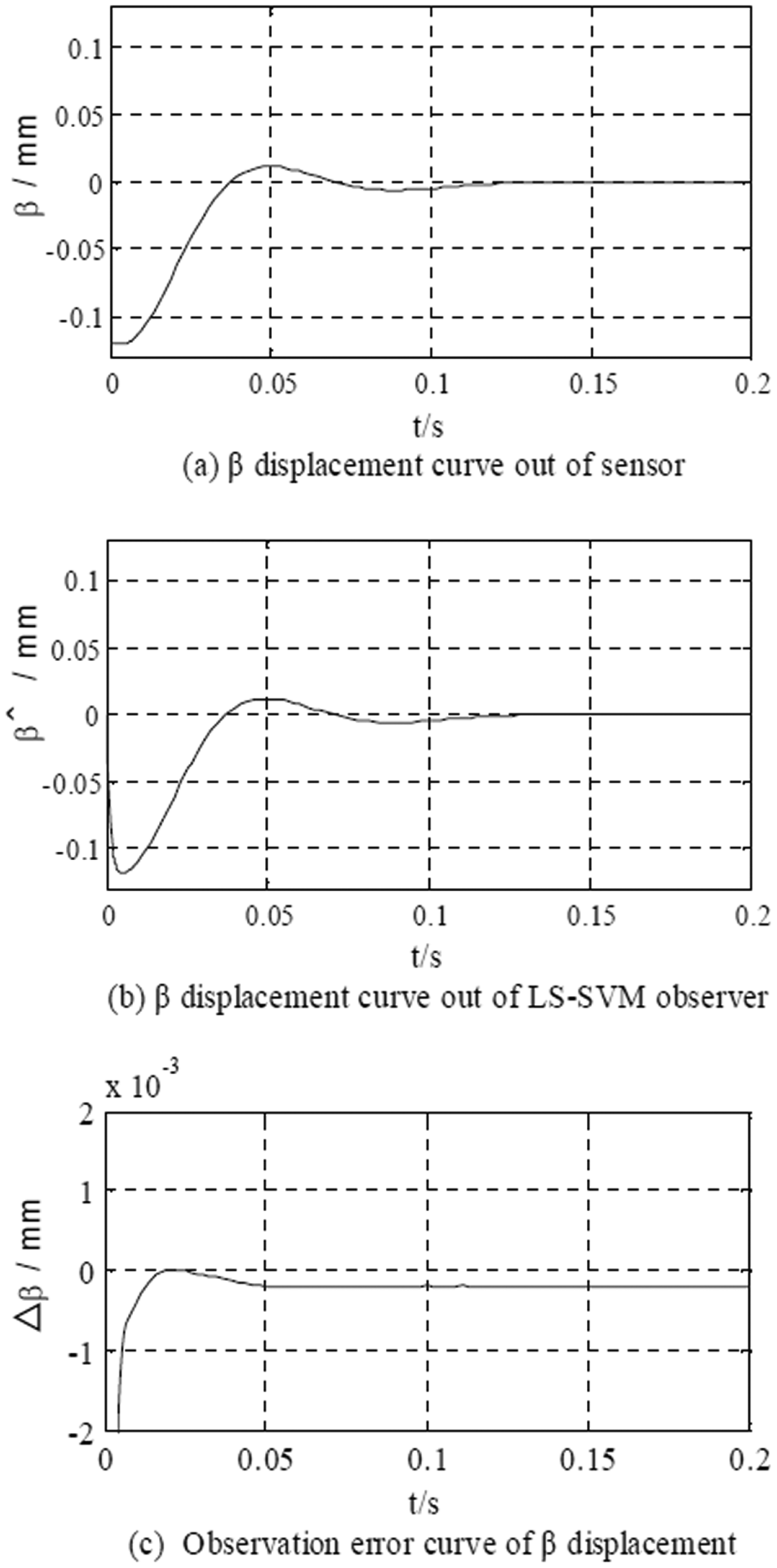
β displacement curves during starting suspension. LS-SVM: least squares support vector machine.
From Figures 5 and 6, the following simulation results are analysed.
Before the suspension of the rotor, the observation values of displacement components are not equal to their actual values. Once the rotor starts to suspend, the observation values of displacement components quickly reach their actual values;
After a brief adjustment, the system is stable, then the outputs of the LS-SVM displacement observer are almost entirely consistent with that of radial displacement sensors; the tracking errors of displacement components stay within the range of 2 μm all the time.
The simulation results illustrate that the proposed LS-SVM displacement observer has excellent performance and higher precision. When the proposed LS-SVM displacement observer is adopted, apart from the short time transition process in starting the suspension stage, the radial displacement of the rotor can be observed with higher precision both in the stable starting process and in the stable suspension operation process.
To validate the effectiveness and feasibility of the proposed LS-SVM displacement observer, under the same simulation conditions, a simulation comparison study between two different cases has been made; one case is that the actual radial displacement sensor is adopted; another case is that the proposed LS-SVM displacement observer is adopted. In order to compare the dynamic response performance of the control system in two cases, the given signals of radial displacement components are suddenly changed at different times. The simulation response curves of α and β displacement components are as shown in Figures 7 and 8.
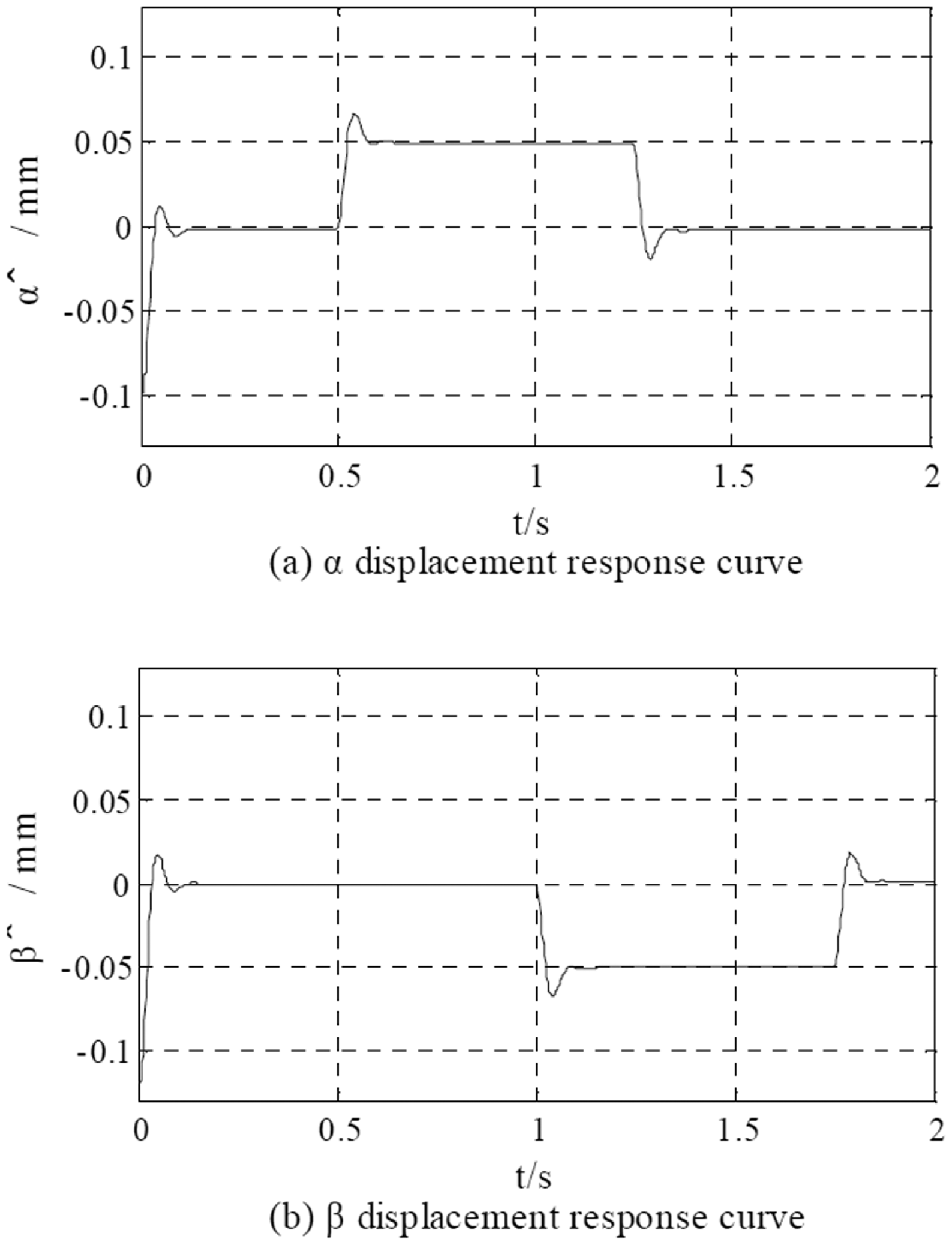
Displacement response curves of the control system when the least squares support vector machine (LS-SVM) observer is adopted.
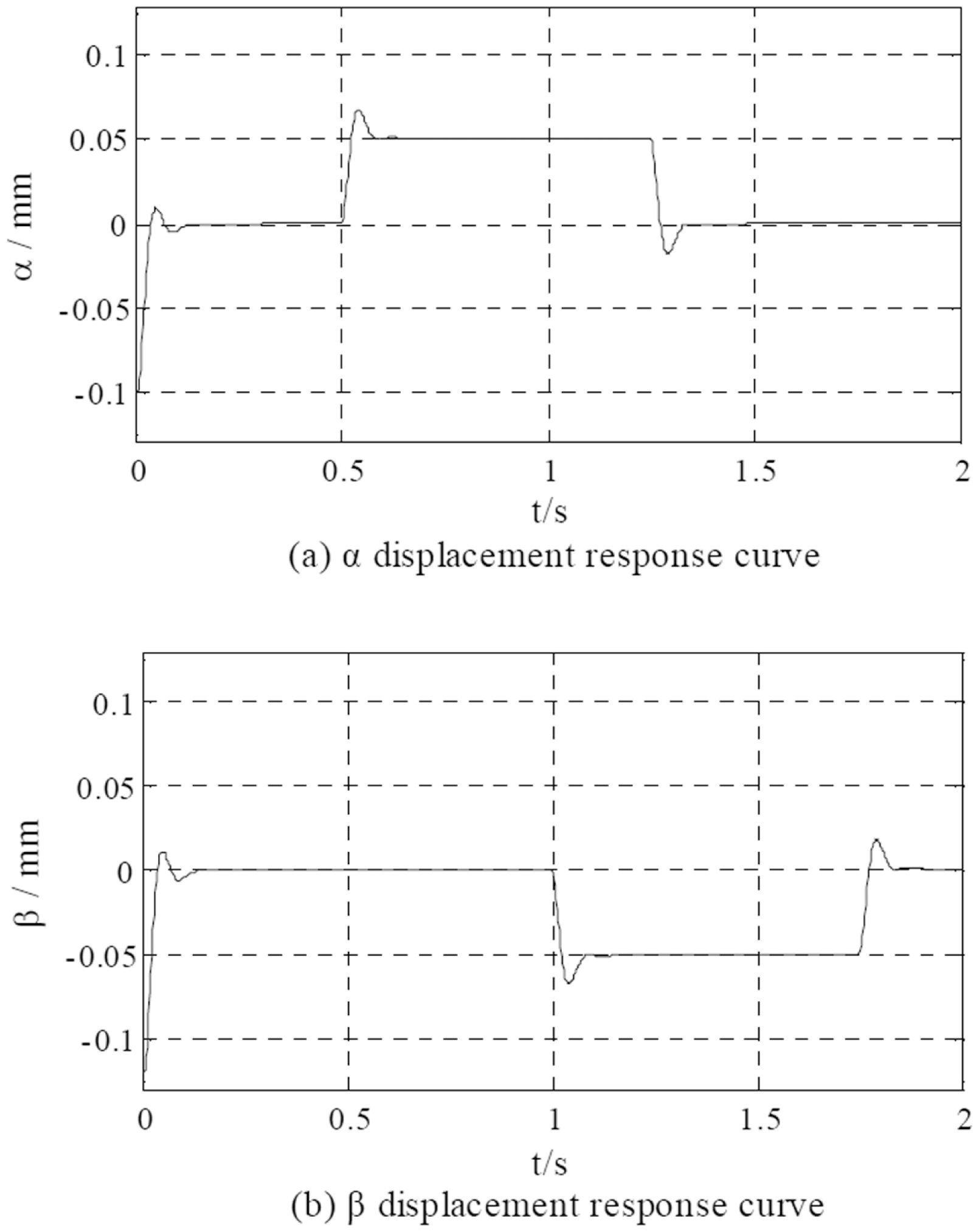
Displacement response curves of the control system when sensors are adopted.
From Figures 7 and 8, the following simulation results are analysed.
Compared with the control system with the displacement sensor, when the proposed LS-SVM displacement observer is adopted, the observer needs to estimate the displacement according to relevant signals, and the establishments of relevant physical variables require a certain period of time, then at the moment of starting suspension, a certain observation delay is produced, which results in the fluctuation amplitude of the displacement component being slightly greater.
Based on the proposed LS-SVM displacement observer, stable suspension operation of the rotor can be achieved. When given signals of displacement components are suddenly changed at different times, the observed displacement components can quickly tack their given signals, and reach their stable status; the observed or estimated displacement response curves are almost entirely consistent with the outputs of actual displacement sensors.
In the output voltage of the actual pulse width modulation (PWM) inverter, there inevitably exists high-frequency harmonic voltage. In order to try to close the industrial reality, the high-frequency harmonic interference signal is added at the output end of torque winding; its frequency and amplitude are 10 KHz and ±10 V, respectively. Then the performance simulation of the LS-SVM observer is carried out. Figure 9 gives the observation waveform of displacement, and for the convenience of comparative analysis, the actual displacement waveform is given also. Figure 10 gives the comparison waveforms of observed displacement between before and after adding the high-frequency harmonic interference signal.
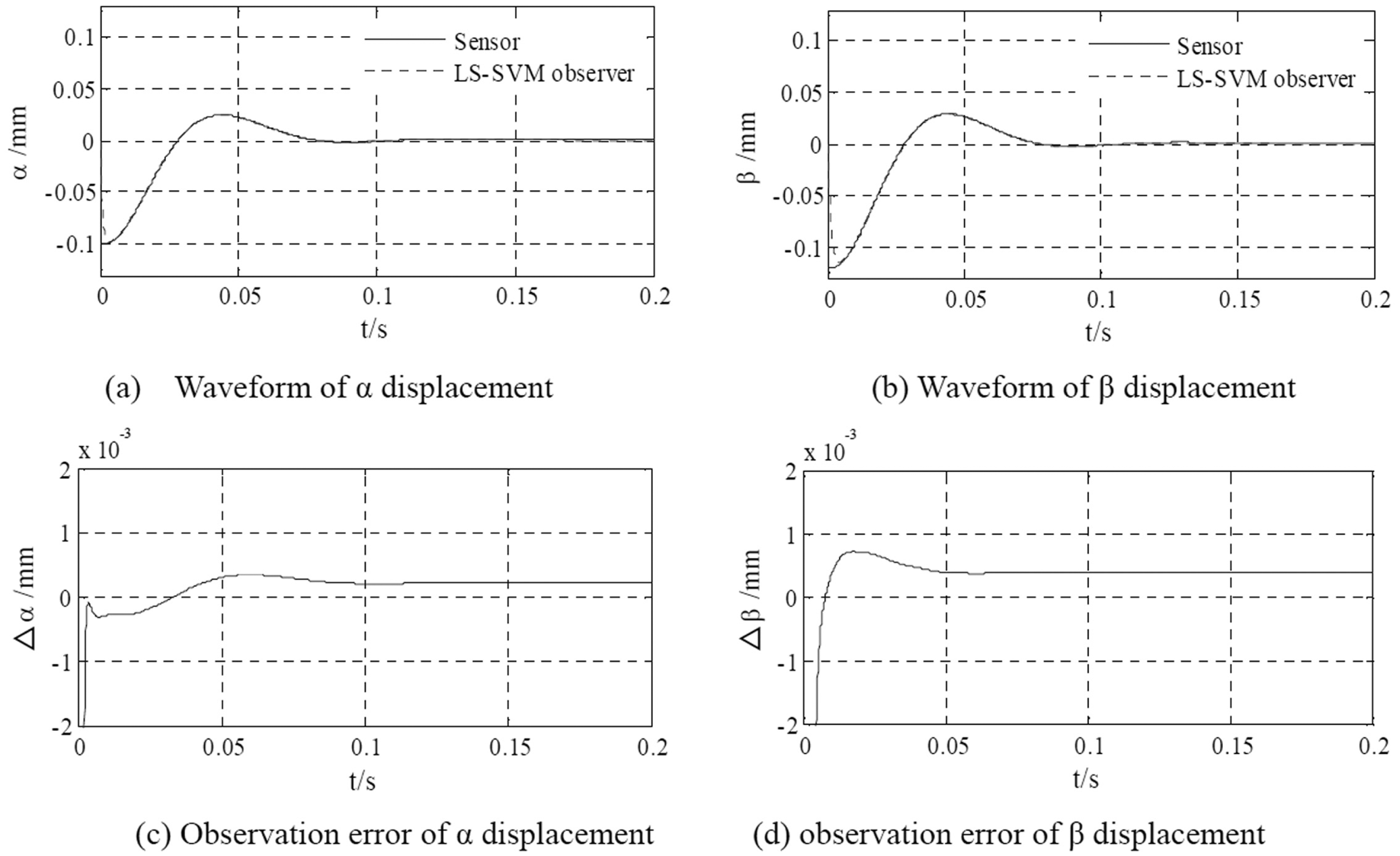
Waveforms of observed displacement when the high-frequency harmonic interference is considered: (a) waveform of α displacement; (b) waveform of β displacement; (c) observation error of α displacement; (d) observation error of β displacement.
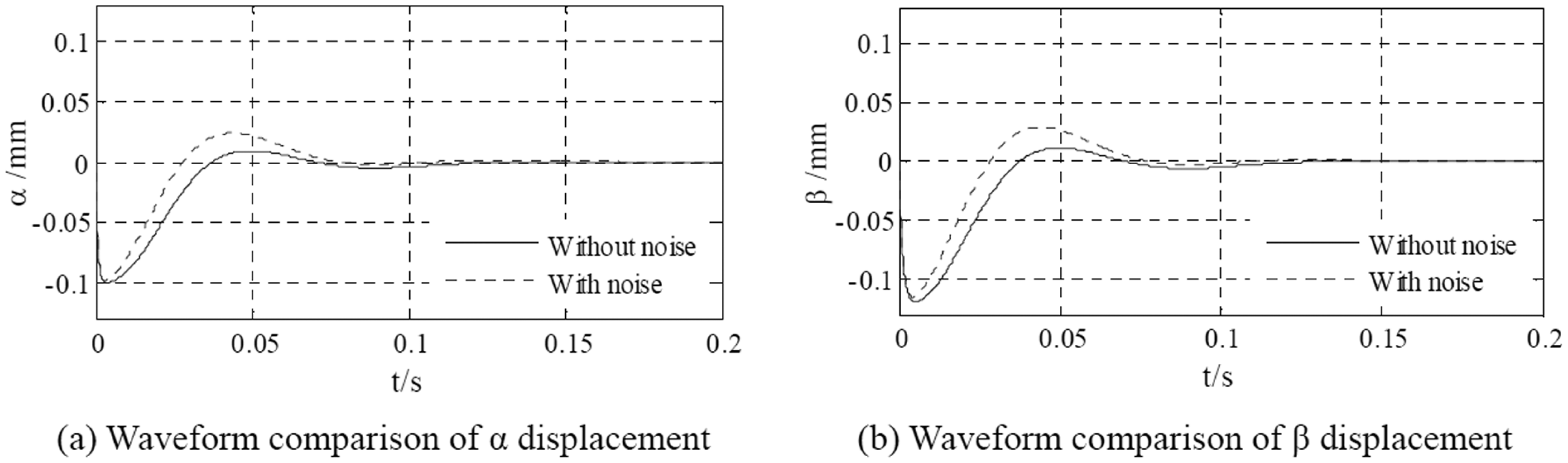
Waveform comparison of observed displacement between before and after the high-frequency harmonic noise interference being considered: (a) waveform comparison of α displacement; (b) waveform comparison of β displacement.
From Figures 5, 6, 9 and 10, the following simulation results are analysed.
After adding the high-frequency harmonic interference signal, the overshoots of observed displacement increase obviously and the displacement overshoots along the α and β directions reach about 25 and 30 μm, respectively. The reason for the overshoot increase is that the high-frequency harmonic voltage causes weak variations of stator current and motor flux linkage.
After adding the high-frequency harmonic interference signal, the radial displacements along the α and β directions can still can be tracked quickly by the proposed LS-SVM observer. Furthermore, there is no increase in the displacement tracking error; the tracking error is still kept within ±2 μm.
The validity and feasibility of the proposed LS-SVM observer have been further verified by the simulation results.
Discussion and conclusion
In this article, a LS-SVM observation method is proposed to achieve the displacement self- sensing detection of the bearingless induction motor, and to reduce the control system cost. Firstly, the state-space model of the magnetic suspension system is analysed, and then the LS-SVM is introduced to the displacement observer. By offline training the LS-SVM, the function vector F(x, u) in the state-space model is approximated by the LS-SVM; through the gain matrix K that is asymptotically stable, the estimated displacement components, that is,
According to the simulation verification and analysis results, there are the following conclusions.
1) When the proposed LS-SVM displacement observer is adopted, the radial displacement of the rotor can be accurately estimated in the steady state; under the condition of no radial displacement sensors, the reliable magnetic suspension operation of the bearingless induction motor can be achieved.
2) When the proposed LS-SVM displacement observer is adopted, both in the starting suspension process of the rotor and in the sudden change process of the displacement component, a faster tracking rate and higher observation accuracy can be achieved.
3) The proposed LS-SVM displacement observer is effective and feasible; at the same time, the motor parameters are not necessary for the LS-SVM observer, and then the influence of motor parameters can be avoided effectively by the proposed LS-SVM displacement observer. In addition, a new technical method has been provided for the radial displacement self-sensing detection of the bearingless induction motor.
In this article, the LS-SVM displacement observer of the bearingless induction motor is discussed and investigated, although system simulation results have shown its good observation performance, effectiveness and feasibility, but in its subsequent application, there are still some problems that should be researched, mainly including the following aspects. Firstly, when the proposed LS-SVM displacement observer is offline trained, the displacement sensor is needed to supply training sample signals. Then how to get rid of the dependence on displacement sensors, and achieve the sensorless online training of function vector F(x, u), is an important problem in the next research. Secondly, if the training sample number is too small, the accuracy of the trained LS-SVM displacement observer cannot be guaranteed; however, if the training sample number is too large, the implement difficulty of the LS-SVM displacement observer will be increased; then the determination principle of the best training sample number for the LS-SVM is an important problem to solve. Thirdly, for the convenience of practical application, it is necessary to do further technical development for the digital realization algorithm of the proposed LS-SVM displacement observer and, during this period, there would be more repeated experimental studies. These problems will be gradually resolved in the follow-up studies.
Footnotes
Conflict of Interest
The author(s) declared no potential conflicts of interest with respect to the research, authorship, and/or publication of this article.
Funding
The author(s) disclosed receipt of the following financial support for the research, authorship, and/or publication of this article: This work was supported by the National Natural Science Foundation of China (51277053), International Cooperation Project on Sci. & Tech. of Henan Province (114300510029) and Nature Sci. Fund of Henan Province Education Bureau (2010B510011).