






Abstract
One of the main renewable energy sources for the future is photovoltaic (PV) energy. Hence, working of the PV systems at maximum efficiency is taken into consideration in recent years. In this paper, for improving the performance of the global maximum power point tracking under partial shading conditions and uncertainty in parameters of DC-DC converter, a two-level adaptive control scheme is proposed. The proposed controller is capable of efficiently handling the uncertainties in the PV systems and the perturbations in the environment. The first level is global perturbation-based extremum seeking control (GPESC), and the second level is model reference adaptive control (MRAC). GPESC is used to find global maximum power point and MRAC is utilized to handle the dynamics of the DC-DC converter. Adequate difference in the time constants of control levels, causes decoupled control levels, which in turn makes it easy to design the controller. The performance of the proposed control scheme is evaluated through simulation based on four indicators: tracking accuracy, tracking efficiency, tracking speed and searching resolution for different irradiance patterns. The results are compared with GPESC and GPESC with PID controller.
Keywords
Introduction
Nowadays, performance improvement of photovoltaic (PV) power systems under variations in solar insolation and environmental temperature has attracted the attention of many researchers (Necaibia et al., 2015). Since the variations of irradiation are much faster than the temperature changes, partial shading conditions (PSCs) has been more considered in the literature. The only way to make the PV systems continuously hand over their theoretical optimal power in different climate conditions is by using a maximum power point tracking (MPPT) algorithm (Khanna et al., 2014). MPPT means that automatic tuning of the PV systems load enables them to get the maximum possible power output. There is a complex relationship between current, voltage, and output power of PV systems making it difficult to extract the maximum power (Koutroulis and Blaabjerg, 2015). A comparative study of MPPT methods for PV power systems can be found in Koutroulis and Blaabjerg (2015), D’Souza et al. (2010) and Yang and Blaabjerg (2015). Perturb and observe (P&O) and modified P&O (D’Souza et al., 2010; MohdZainuri et al., 2014), incremental conductance (IC) and modified IC (Faraji et al., 2014; ; Hsieh et al., 2013; Sekhar and Mishra, 2014), ripple correlation control (Barth and Pilawa-Podgurski, 2015; Moo and Wu, 2014), fuzzy logic, neural network (Yau and Chen, 2012; Zhang and Bai, 2008) and particle swarm optimization (PSO; Duan et al., 2015) are the other popular techniques for extraction of the maximum power in the PV systems. These methods vary in complexity, range of effectiveness, convergence speed, implementation hardware, cost and popularity. On the other hand, uniform illumination intensity in a PV array is not almost satisfied because of buildings or trees shades, atmosphere fluctuation, existence of clouds and daily sun angle changes. As it is seen in Figure 1, partial shading across a PV string can lead to multimodal P–V characteristics. The global MPPT (GMPPT) strategy under such conditions is a complex and challenging task. The conventional MPPT algorithms remain trapped in one of multiple local maximum power points (LMPPs) of the PV pattern (Bizon, 2016a; 2016b).

The PV characteristics for the seven SX60 modules in series connection under different irradiance sequences.
Tracking a varying extremum (maximum or minimum) of a performance (output, cost) function is called the extremum seeking control (ESC; Zhang et al., 2016), which has two layers of meaning: first, the need for seeking an extremum of the performance function; second, the need for stabilizing the system and driving the performance output toward that extremum. The ESC is trying to accomplish real-time optimization for dynamic systems containing unknown dynamics (Ariyur and Krstic, 2003; Zhang and Ordóñez, 2012). Perturbation-based and model-based methods are two important classes of the ESC approaches. Some improvements of the ESC-based numerical optimization have been reported in Ghaffari et al. (2015). Perturbation-based extremum seeking control (PESC) method is a model-free optimization algorithm, so it is suitable for applying to various applications such as MPPT in PV systems (Ahmadi and Zargarzadeh, 2015; Ghaffari et al., 2015; Lei et al., 2010; Moura and Chang, 2013). But ESC methods are not popular as the other conventional MPPT methods mentioned before (Bizon, 2016a). The PESC has the advantages of fast convergence and guaranteed stability over a range of environmental conditions. In addition, it is simple to implement, which, in turn, makes it very cost effective in terms of processing/hardware requirements (Ghaffari et al., 2015). In the last decade, modified versions of PESC algorithm have been used for GMMPT in PV systems. In order to deal with the multimodal
In PV systems, regulating the voltage or current of the solar panel is done by a DC-DC converter. Three famous standard types of DC-DC converters are buck converter, boost converter, and buck-boost converter. In this work, the PV system has been integrated with the boost converter in order to deliver optimal power to the load. Conventionally, proportional integral (PI) or PI derivative (PID) control schemes are proposed for the boost converter via root-locus method or pole-placement technique (Alvarez-Ramirez et al., 2001; Cortes et al., 2004; Ding et al., 2007). However, when system parameters are uncertain, these methods cannot afford to determine the suitable PI (or PID) control gains. Therefore, various kinds of adaptive control that are able to deal with the plants with uncertain parameters have been proposed (Konstantopoulos and Alexandridis, 2015; Salhi et al., 2015). Among the various kinds of adaptive control, model reference adaptive control (MRAC; Black et al., 2014; Ioannou and Fidan, 2006; Sastry and Bodson, 1989) is the most popular and effective ones. MRAC is a control system structure in which the desired performance of the system with unknown parameters is expressed in the terms of the reference model that gives the desired response to the command signal. The command signal is fed to both the reference model and the actual system. Then the controller adapts the gains such that the actual system will respond like the reference system and the error between their outputs will be minimized.
In this paper, a two-level GMPPT control has been constructed. At the first level, global perturbation based extremum seeking (GPESC; Bizon, 2016b) has been used to determine the optimal duty cycle of the boost converter for reaching to the GMPP in the steady state (when the dynamics of the DC-DC converter has been neglected). The main contribution of this work in comparison to Bizon (2016b) is that unlike that research, a dynamic model for PV system has been considered: a second order transfer function has been derived as the model of the boost converter; while the relation of the output power and voltage contains a nonlinear map similar to Bizon (2016b). Considering the dynamic model of the converter requires the addition of adaptive control level to capture the converter’s dynamics in order to reach the desired transient performance. Consequently, we have utilized GPESC proposed by Bizon (2016b) only as the first control level. In Bizon (2016b), there is no second control level, and dynamic behaviour of the converter has been neglected. In other words, regardless of the uncertain dynamic model for the boost converter, GPESC without MRAC yields high performance in GMPPT; but, considering the uncertain dynamic model for the boost converter causes inability of GPESC without MRAC in GMPPT. Therefore, the GPESC with MRAC has been proposed to succeed in dealing with this difficulty. Owing to the unknown parameters of the PV array, the response of the converter to the previous mentioned duty cycle maybe undesired. Therefore, at the second level, the desired response of the boost converter has been achieved by the MRAC scheme. During adaptation, the error between the plant and the reference model has been utilized to tune the parameters of the controller. The two-level structure of the GMPPT algorithm reduces the complexity of the design and implementation by GPESC handling the slow dynamics (steady state behaviour) and MRAC handling the fast dynamics (transient behaviour). In this manner, there are two stable systems: GPESC-level has a large time constant and MRAC-level has a small time constant. Thus, the proposed two-level structure can effectively decouple GPESC and MRAC levels in the design and analysis. It is also worth mentioning that connection of two stable systems will not necessarily lead to a stable system; but, if their time constants are so far from each other, they can be considered decoupled. To the best of our knowledge, it is for the first time that GPESC and MRAC have been joined together for GMPPT in PV systems to reach the desired response. Four indicators have been used for evaluating the performance of the proposed control scheme in different irradiance patterns.
The paper has been organized as follows: In Section 2, the problem formulation for GMPPT of the PV system as well as the dynamic model of boost converter have been presented. A two-level adaptive control algorithm for GMPPT has been described in Section 3. Simulations and results have been presented in Section 4 to illustrate the effectiveness of the proposed method. Finally, a conclusion remark has been given in Section 5.
Problem formulation
PV characteristics
In this work, the one diode model of the PV cell has been considered. The model has been constructed with an ideal current source

where

where
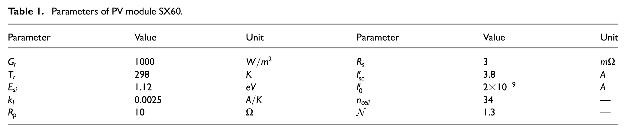
Parameters of PV module SX60.
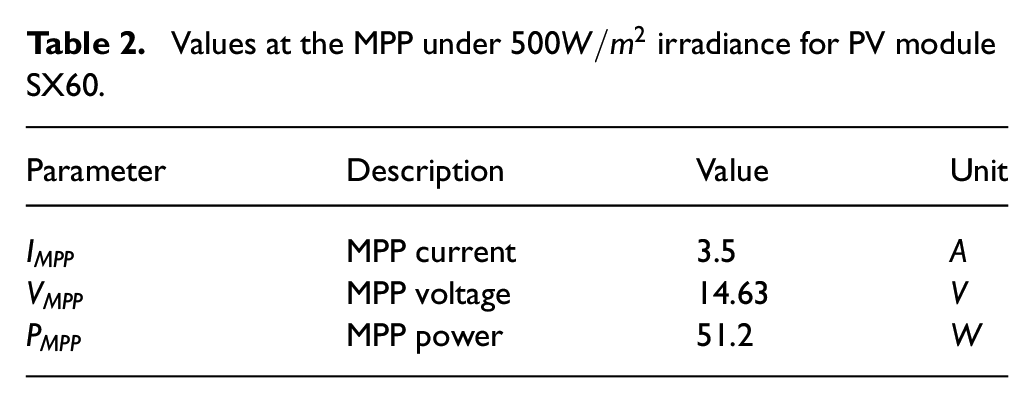
Values at the MPP under
Converter dynamics
Illustrated by Figure 2(a), the boost converter transfers the power produced by the PV array to the power consuming components (load) at higher voltage level. It is worth mentioning that other kinds of power converter may also be used in place of the boost converter according to the application. Based on Figure 2(a), the duty cycle d that is tuned by GMPPT controller has been applied to switching device Q. The relationship between the duty cycle of the switch Q and voltage of PV array is (Khanna et al., 2014)

in which

(a) A typical PV energy system based on the boost converter. (b) Small signal equivalent circuit of PV array connected to the boost converter. The battery storage set has been considered as the load.
For the design of the MRAC, it is needed to connect a dynamic model of the boost converter to the output of the PV array. The current-source of the PV Array has an effect on the input-current-based feedback controller such that it may easily be saturated under the climatic conditions changes. Because of that, it is recommended that the input-voltage-based feedback control is used (Messo et al., 2012). In this work, a small signal equivalent circuit, as suggested in Khanna et al. (2014) and Femia et al. (2005), has been considered. This model is shown in Figure 2(b). A resistor
According to Figure 2(b), the load of the boost converter, which is a storage battery set, yielding the voltage over the output capacitor is kept constant by the load voltage in each switching interval. This will cause only the output impedance to be affected by the output capacitor. Based on Figure 2(b), the transfer function from the control signal
In the steady state condition, the relationship between the operating duty cycle, D, and the steady-state DC input voltage of the boost converter

in which

where s is the Laplace variable,

which is actually a second order linear model of Figure 2(b) around the operating point. The values of
Proposed GMPPT algorithm
In this section, a two-level control structure is proposed for GMPPT. This structure is shown in Figure 3. In the first control level, GPESC has been used to compute v for delivering the maximum available power of the PV array to the load in the steady state. Converting v to the duty cycle

Proposed two-level control structure.
Global perturbation-based extremum seeking control
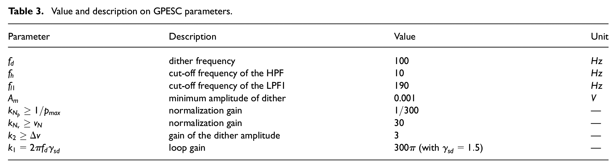
In this subsection, the GPESC based on Bizon (2016b) is presented. The diagram of the GPESC is shown in Figure 4. Specifications of the GPESC parameters are presented in Table 3. The mean value (MV) block computes the MV of the filtered probing signal during a dither period to produce extra smooth signal. The

where, (7) represents the static map, normalization, band pass filtering, demodulation, integration, computation of the gain dither (

The GPESC diagram for GMPPT in the PV system.
Value and description on GPESC parameters.
Stability analysis of the above GPESC scheme is based on averaging stability analysis technique that has been completely presented in Bizon (2016b) and it has been removed here for the sake of time.
Model reference adaptive control
In the previous section, the first control objective was achieved and GPESC was utilized to compute the duty cycle for GMPPT in the steady state. The second control aim is to reach the response of the overall system with appropriate characteristics. For this reason, the MRAC has been applied to achieve the desired response. In MRAC, the output of the actual system is continuously compared with the output of the reference model. The reference model is the one that gives the desired response to the command signal. Both the actual system and the reference model are motivated by the same command signal. The goal is to decrease the differences between the two outputs, it means that the actual system responds like the reference model (desired) system. For this purpose, the controller adapts the gains such that the output tracking error will be minimized. The proposed scheme of MRAC is shown in Figure 5. The plant model in Figure 5 is the boost converter of which its transfer function is described by (6). The input to overall system

where

in which

(a) The structure of proposed MRAC in the second control level. (b) The controller structure in the proposed MRAC.
According to Figure 5(b) and based on Ioannou and Fidan (2006), and Sastry and Bodson (1989), the adequate controller structure for the objective control is

In above controller structure,

The vector
Suppose that the nominal parameter values are

Let

With an augmented state vector

where matrices

According to (14) the state vector

where
Now, to obtain the dynamic of the output error, consider the following steps

where

Since a necessary condition for state error equation is being strictly positive real (SPR), which is not satisfied here, the identity

where
Now, consider the following transformation

Using that, the following relations are established

where
To find the suitable adaptive laws, consider the Lyapunov function as

where Γ is an arbitrary symmetric positive definite matrix and

where the vector

for any given symmetric positive definite matrix L. Since

to have the derivative of the Lyapunov function negative.

This implies that
Totally, the equations of the overall MRAC scheme are

Based on Ioannou and Fidan (2006), all signals in the closed-loop system are bounded and
Simulation results and discussion
In this section, the proposed control structure has been compared with two methods: the GPESC which is proposed in Bizon (2016b), and with GPESC with PID for GMPPT in PV array in different PV patterns.
For the switch Q of the boost converter, the pulse width modulation (PWM) technique with switching frequency
The equation (6) has been used for designing of MRAC, not for simulation. Indeed, the boost converter has been simulated based on its real model, using Simscape (Electrical) Toolbox of Simulink®. Therefore, the dynamic behaviour of the controller for the real model of the boost converter with all parasitic components has been studied in the simulations.
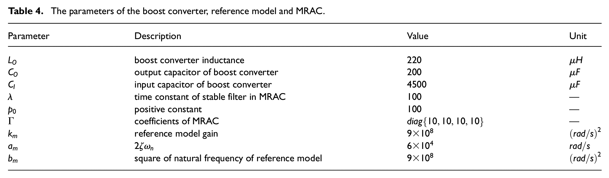
The boost converter specifications, the parameters of the reference model and MRAC used in simulations have been presented in Table 4. The other parameters used in the simulations were mentioned before in Table 3. But the normalization gains should be modified for each PV pattern. If the maximum speed changes in shaded conditions is 10 times per second, then
The parameters of the boost converter, reference model and MRAC.
Four indicators have been utilized: searching resolution (


where
In the all scenarios of the simulations, GPESC is unsuccessful to track the GMPP for the dynamical system with uncertainties and the output power of PV system is converged to zero. But because of page limitation, the results of this approach have not been presented and for a fair comparison, the GPESC with a PID controller used to handle the dynamic behaviour of the boost converter has been considered. Also, the proposed scheme has been compared to GPESC with PID controller. The PID coefficients have been tuned as
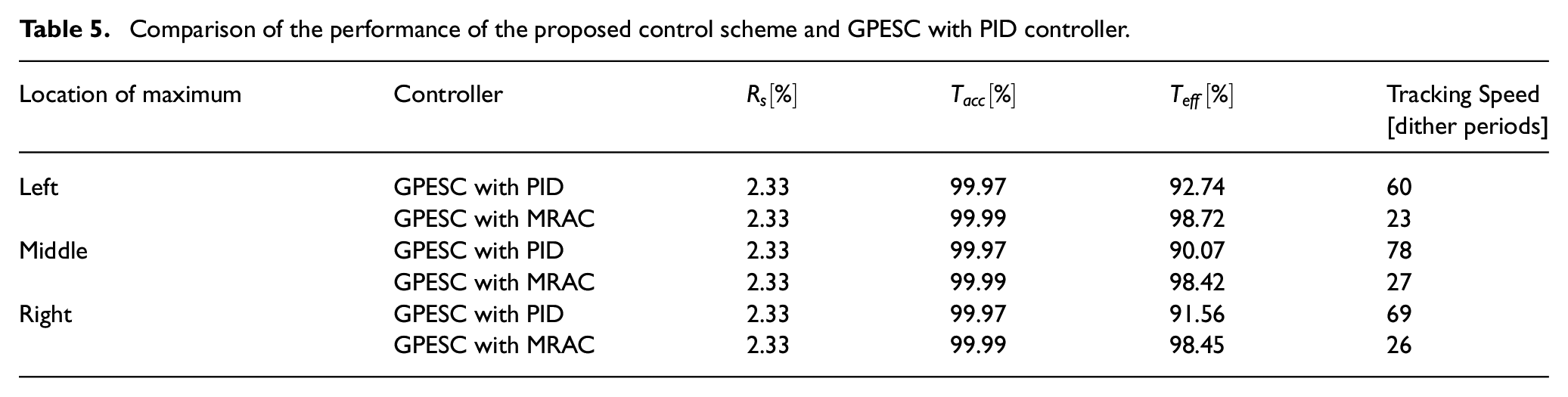
The simulation results are shown in Figures 6 to 8 for the different PV patterns. Based on these figures, one can see that the proposed control scheme can track GMPP in the different scenarios. Although GPESC with PID controller is also successful in tracking the GMPP, the better performance of the proposed scheme is obvious in all the scenarios. As is illustrated in Figures 6 to 8, the steady state, the ripple of voltage and power is so small in both methods. But, in the transient, these components have ripple. It should be noted that the transient time in the proposed method is very short. So, voltage and power reach to steady state with no ripple in a very small time. In Table 5, the comparison of the proposed structure with GPESC with PID in the three patterns has been presented based on the indicators that were explained before. It should be explained that based on (28), the searching resolution for all PV patterns is

Comparison of GMPP searching in the GPESC with MRAC scheme and the GPESC with PID controller: (a) PV pattern with GMPP in left, (b) PV power, (c) PV voltage.

Comparison of GMPP searching in the GPESC with MRAC scheme and the GPESC without MRAC: (a) PV pattern with GMPP in middle, (b) PV power, (c) PV voltage.

Comparison of GMPP searching in the GPESC with MRAC scheme and the GPESC without MRAC: (a) PV pattern with GMPP in right, (b) PV power, (c) PV voltage.
Comparison of the performance of the proposed control scheme and GPESC with PID controller.
Conclusion
In order to deliver the maximum available power from the PV array to the load, the two-level GMPPT control structure, was proposed. In the first level, GPESC was utilized to calculate the setpoint for GMPPT in the steady state. In the second level, the dynamic model for the boost converter was constructed; then, MRAC was used to achieve the desired dynamical performance in the response to the setpoint calculated by GPESC in the previous level. This level compensated the underdamped characteristics of the boost converter. Owing to the satisfactory difference in time constant of each level of the control structure, the design and analysis of those levels was decoupled. Therefore, the difficulty of designing and implementation was reduced. The simulation results demonstrated that owing to the converter dynamics, the GPESC cannot reach the GMPP. The performance of the proposed method was evaluated based on four indicators: searching resolution, tracking accuracy, tracking efficiency and tracking speed. Based on the simulation results, one can see that GPESC with MRAC yields the better performance in comparison with GPESC with PID controller. For future work, stability analysis of combined GPESC and MRAC will be studied.
Footnotes
Declaration of conflicting interest
The author(s) declared no potential conflicts of interest with respect to the research, authorship, and/or publication of this article.
Funding
The author(s) received no financial support for the research, authorship, and/or publication of this article.