






Abstract
In this paper, a new technique to improve initial rotor position detection at standstill of a permanent magnet synchronous motor (PMSM) is presented. Sensorless field-oriented control (FOC) of a PMSM at low speed remains a difficult task. In order to estimate the position and rotor speed, we proposed a novel structure of a full-order sliding mode observer (FO-SMO) in a sensorless FOC. At standstill, we used a voltage pulse sequence applied to the windings in order to detect the initial rotor position. With this technique, we managed to minimize the error on the estimated rotor position to 3.75° (electrical) compared with others. The validity of the proposed approach with a 1.1-kW low-speed PMSM sensorless FOC has been proved by experimental results.
Introduction
The permanent magnet synchronous motor (PMSM) presently attracts attention in an industrial domain thanks to several favourable characteristics such as low inertia, high efficiency and low weight. For sensorless field-oriented control (FOC) of a PMSM drive, accurate knowledge of the rotor position and speed is required by using either a rotor position encoder or an estimator. The use of these sensors leads to the emergence of some problems, for example the cost of the sensor, increased equipment complexity and reduction of the mechanical robustness (Acarnley and Watson, 2006). Scientific research has evolved to solve these problems; a sensorless vector control technique has been developed for variable speed PMSM drives (Delpoux and Floquet, 2014; Lee, 2015; Yang et al., 2016), instead of using a rotor position sensor. Consequently, many methods for rotor position and speed estimation have been researched.
Generally, sensorless vector control approaches can be classified into two categories: high frequency injection techniques using the rotor salient effect of the motor (Wu and Selmon, 1991) and estimation methods based on the observer (Tomei and Verelli, 2011). In order to estimate the rotor position and velocity, several studies have used the extended Kalman filter (Boussak, 2005), the model reference adaptive system (Khlaief et al., 2013), the non-linear observer (Khlaief et al., 2016) and the sliding mode observer (SMO) (Qiao et al., 2011; Saadaoui et al., 2015, 2016). The latter observer is widely used in the research domain due to its robustness towards parametric uncertainties. This approach is based on the technique of a sliding mode and two observers model have been studied; regarding the first model, many proposed methods are based on the back electromotive force (EMF) (Kim et al., 2011), and the second is based on the full-order SMO (FO-SMO) (Corradini et al., 2012; Kim et al., 2011; Saadaoui et al., 2015).
In Kim et al. (2011) and Qiao et al. (2011), the SMO has been proposed in order to estimate the rotor position and velocity. The authors present a new sliding mode observer of the PMSM.
Several studies on reducing the chattering phenomenon and the important efforts based on high-order sliding modes methods to overcome this difficulty have been published (Corradini et al., 2012). Saadaoui et al. (2015) propose a sensorless speed control for a PMSM based on FO-SMO. The simulation results show the effectiveness of the new SMO approach.
The FO-SMO technique is not able to detect the initial rotor position of the PMSM. At start-up, without the knowledge of the initial rotor position, the motor can rotate in the wrong direction, which is not allowed in some industrial applications.
Boussak (2005), Saadaoui et al. (2015) and Schmidt et al. (1997) used a method based on a voltage pulse. This technique consists of feeding the stator of the PMSM in various phases by a voltage pulse sequence. With this approach, we managed to minimize the error on the initial rotor position detection to 3.75° (electrical) without additional materials. The sensorless FOC approach with initial rotor position detection of the PMSM drive is applied in a Matlab-Simulink program and a dSpace DS1103 controller board.
This paper proposes a sensorless FOC of PMSM based on new FO-SMO with initial rotor position detection. The following section presents the PMSM model and then we propose a new FO-SMO. The principle of the proposed initial rotor position detection is developed, and experimental results of the sensorless FOC are presented and discussed. Finally, we draw conclusions relating to the contribution of this paper and present proposals for future work.
PMSM modelling
The PMSM model is presented as follows:

where:
Proposed SMO
In this next subsection, a sigmoid function replaces a sign function in order to eliminate the chattering phenomenon. Therefore, the use of a low pass filter is not necessary.
Sigmoid function
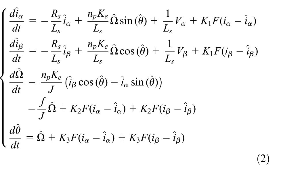
The observer is based on a stator current estimator as stator currents and voltages. Then, a new FO-SMO can be constructed as follows
with
The sigmoid function is given by this expression

where
Stability analysis
The sliding surface

where
For the PMSM sensorless FOC, we used the following Lyapunov function to obtain the sliding condition

with
We take the time derivative of (5), which can be found as

The dynamic error equations are given by

Substituting (7) in (6) gives

with

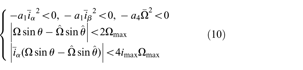
To guarantee the convergence, the Lyapunov function derivative is forced in such a way that
Knowing that
Such that

Therefore
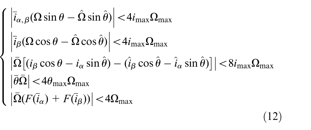
We have selected K1, K2 and K3 so that
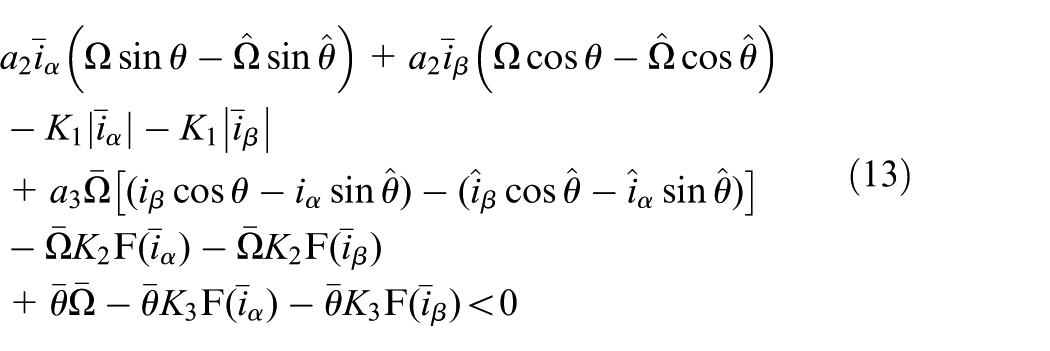
Therefore,

The structure of the sensorless FOC of PMSM by using the new FO-SMO is shown in Figure 1.

Block diagram of the sensorless field-oriented control of permanent magnet synchronous motor: (a) overall block diagram of system; (b) block diagram of the synchronous motor observer.
Initial rotor position detection
To received good operation at the start-up of the sensorless FOC of the PMSM, we must know the initial position of the motor (Haque et al., 2003). Furthermore, we are obliged to add a new technique to detect the initial rotor position of the PMSM.
We apply a suitable sequence of voltage pulses to the winding of the PMSM. Evaluation of the different signs of the peak current leads to initial rotor position information (Boussak, 2005).
The proposed detection method
We used the DSP (dS1103) to beget these impulses to inverter legs (represented in Figure 2).

Three possible switching sequences for three-phase permanent magnet synchronous motor.
The voltage equations can be presented as follows:
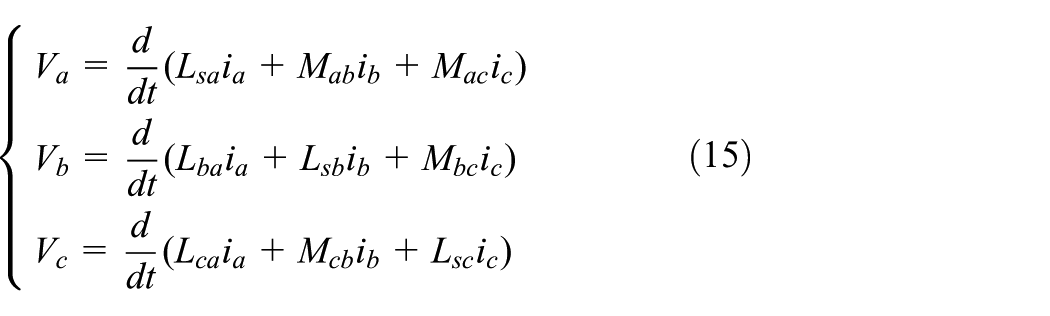
with


Given that the system is supposed to be linear, the suppression of the current
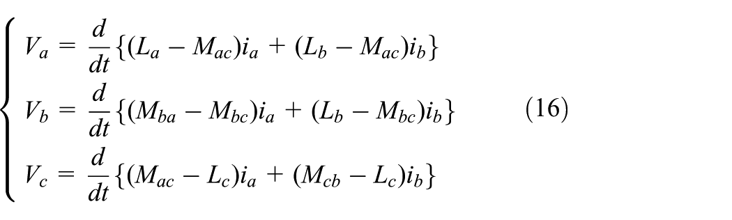
From the connection configuration of the phase to the PMSM test vector
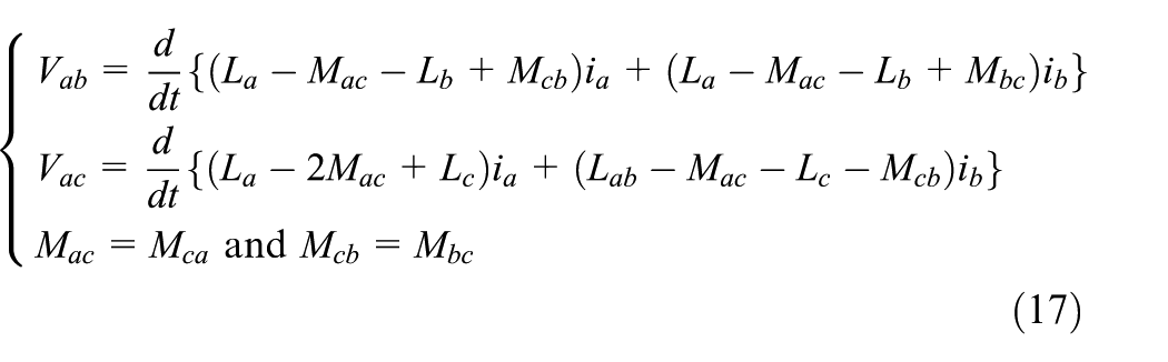
After all calculations are performed, the expression of the current of the phase a is represented by:
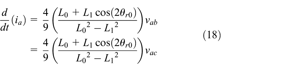
where
L0: component of the self inductance due to space fundamental air-gap flux;
L1: component of the self inductance due to rotor position dependent flux.
We find that the coefficient-related voltages are represented by:

with

and

Applying a positive voltage pulse

with
In the same way, the expressions of the currents that correspond to the voltage vector
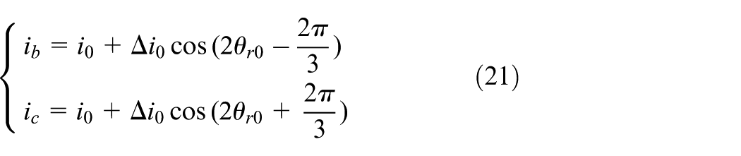
We can observe that the monotonous function lets us substitute the currents of the stator by their respective differences
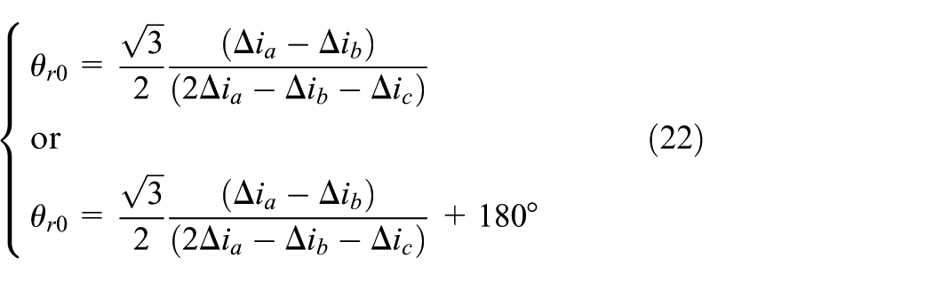
We can determine, while using (23), the values in Table 1 for the initial position detection.
Initial position estimation.
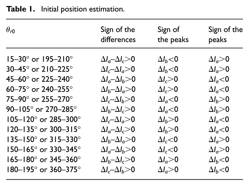
We conclude that, according to the Table 1, it is possible to detect the initial position of the rotor with two different values. This problem is resolved in the next subsection. To overcome this problem, another short-length test signal is applied in order to receive a saturated magnetic circuit of the motor winding.
After all

Experimental results of the peak currents versus rotor position.
The experimental results (Figure 3) confirm the feasibility of the proposed initial position estimation approach.
Discrimination of the uncertainty of the initial rotor position
This method consists of applying a pulse voltage to a saturated induction motor (Boussak, 2005).
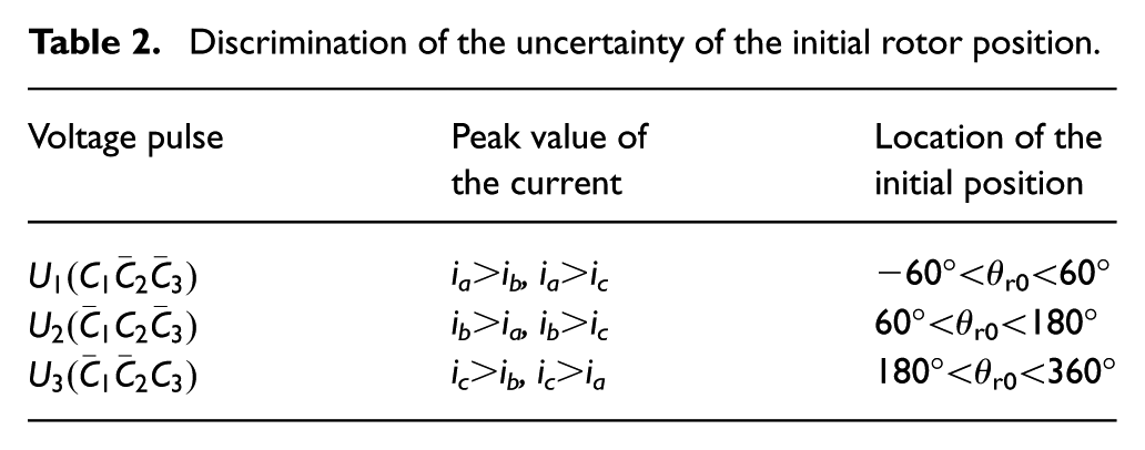
Figure 4 gives the discrimination of the two values of the initial position. If the magnetic flux is in the same direction as that engendered by the current pulse, we obtain an additive flux and therefore a large peak current. In the other case, we obtain a descending field. Therefore, the initial rotor position corresponds to a current of the most important variation. When the north pole of the field is close to one axis of the three phase windings, the current peak is the most important in the considered phase. By considering the study previously developed to avoid the ambiguity on the accuracy concerning the rotor initial position estimation, we can produce the results in Table 2.

Discrimination of the two values of the initial rotor position.
Discrimination of the uncertainty of the initial rotor position.
Reduction of the error detection
The initial position

Application of the 12 test vectors for
We can see in Figure 6 that the two vectors

Currents id representation for each voltage vector for
After the verification that the nearest vector to the d-axis shows us the rotor position, it is possible to integrate this technique in a sector of 15° to minimize the initial position detection error, which is represented by Figure 7.

Principle for the error reduction of initial position
In the first sector and a real angle of the rotor equal to 19° (electrical), located between 15° and 30°, Figure 8 shows us that vector

Current
Therefore, we can note that the vector
In Figure 9, the experimental results of the rotor position estimation error (

Estimation error versus real rotor position.
According to this figure, we can conclude that the accuracy obtained during our tests is sufficient to reset the sensorless FOC algorithms, as the maximum error is about 3.75° (electrical). The obtained initial position estimation value is generally sufficient to eliminate random movement and reaches a stable start during start-up.
Experimental results and analysis
Experimental set-up
The experimental set-up is represented in Figure 10. It is based on the card from dSpace DS 1103, a PMSM, power inverter, driver IR 2130 in order to amplify the SVPWM signals generated by dSpace DS1103 card and active load used to change the load torque. The active load consists of an auto-start synchronous motor, a brake resistor and a load control drive. An incremental encoder with 4096 pulses per revolution is used only to obtain the position signal, which is solely used for comparison with the estimated speed and position.

Picture of the experimental apparatus.
Experimental results
A sensorless FOC of PMSM drive has been implemented in the Matlab/Simulink toolbox, as indicated in Figure 1. The rated parameters of the PMSM and controller are given by Tables A1 and A2 in the Appendix.
In order to verify the dynamic performances of the proposed sensorless algorithm, many experimental tests have been carried out (Figures 11 and 12).

Sensorless field-oriented control using the sigmoid function.

Experimental results with speed reference of 500 rpm: (a)
Figure 11 illustrates the experimental results of sensorless FOC using a sigmoid function at 500 rpm with initial rotor position equal to zero (
The application of sigmoid function does not require the use of a low pass filter, which allows the building of a time delay.
These results show that FO-SMO sensorless FOC based on sigmoid function can estimate correctly the rotor position and speed during the speed operation.
Example of initial rotor position detection
Figure 12 gives an example of initial rotor position estimation with the start-up of the PMSM drive. Before starting, Figure 12(a) and (b) give the waveforms speed at standstill when we applied the voltage pulse to the stator winding with initial rotor position
The PMSM is accelerated to 500 rpm with a speed reference. Figure 12(b) shows the zoomed measured and estimated position at start-up.
To estimate the initial rotor position, two kinds of suitable sequence dc voltage rectangular pulses are applied from the inverter to the stator windings of the motor at standstill. One voltage pulse is applied with a short time duration Tsh, another with a long time duration TL. The motor starts rotating with the estimated rotor position with the FO-SMO technique.
Before starting, the rotor did not move, but the appearance of a small vibration on the rotor is noteworthy. After monitoring the peak currents (Figure 12c), the detected initial rotor position is about 2.1 electrical radians (Figure 12b). The estimated and the actual rotor position are very close, as shown in Figure 12(b). In Figure 12(d), the experimental results show the rotor speed error. The estimated and the actual rotor speed are very close, and the estimation error using the FO-SMO method does not exceed 9 rpm during transients and 0.08 rpm at steady state (Figure 12d). In Figure 12(d), we can observe that the load increases to 2 Nm; this increase is due to the coupling of the MSAP with the auto-synchronous motor without application of the load torque. It can be observed that the estimated position tracks the actual rotor position very well.
These results confirm the feasibility of sensorless FOC of PMSM drive. We also note that experimental results show validity of the method applied for estimation of the initial rotor position of the PMSM.
Conclusion
In this work, the use of the FO-SM observer leads to estimate the rotor speed of the PMSM drive. To avoid the chattering phenomenon in the FOC, we used the proposed observer, which applies a novel switching function commonly called the sigmoid. The stability of FO-SMO has been proved by the use of a Lyapunov stability analysis.
The FO-SMO is not observable at standstill; for this reason, it is not capable of estimating the initial rotor position for the PMSM. Therefore, we applied a voltage pulses tests approach to detect the initial rotor position.
The sensorless FOC has been experimentally validated using a dSpace DS 1103. Experimental results show that the proposed FO-SMO for sensorless FOC for PMSM is able to estimate precisely the speed and rotor position. These results proved the effectiveness of the proposed sensorless FOC of PMSM drives with detection of initial rotor position at standstill.
In future, we will be interested in detecting the initial rotor position at standstill for salient-PMSM.
Footnotes
Appendix
Parameters of controller.

| Pole | 6 |
| PI currents controllers | |
| IP speed controller | |
| SMO gains |
PI, proportional–integral; IP, interior permanent; SMO, sliding mode observer.
Declaration of Conflicting Interests
The author(s) declared no potential conflicts of interest with respect to the research, authorship, and/or publication of this article.
Funding
The author(s) received no financial support for the research, authorship, and/or publication of this article.