
Abstract
In this paper, a new control method is presented for the 4-poster test systems. The primary aim of the paper is to improve the convergence speed and decrease the error rate for model-based iterative learning control (ILC), a widely used method as a tracking control. First, the dynamic equations of the system are generated, and the control problem is formulated. Then, an inverse model of the system is established directly through the adaptive neuro-fuzzy inference system (ANFIS) with auxiliary parameter (piston position) as a serial combination of two sub-models. In order to construct a neuro-fuzzy ILC (NFILC) structure, these sub-models are integrated into the neuro-fuzzy inverse controller (NFIC). Because of this new structure, the modified ILC rule has two layers. In the first layer, the controlled parameter, namely, the acceleration is iterated, whereas, in the second layer, the auxiliary parameter is iterated. The outcomes of the proposed control method are scrutinized by testing through a numerical simulation. Finally, it is demonstrated that the modified ILC rule dramatically increase the convergence speed and reduce the final error rate.
Introduction
The purpose of test systems is to determine the performance and durability of a product. Based-on intended use(s) and purpose(s), there exist pseudo-static and dynamic (fatigue) test systems. While the pseudo-static test systems are mainly applied to type approval and durability tests, the dynamic test systems are used for the determination of fatigue and lifetime of a product. Before performing a fatigue test, the loads to be applied on a product by the test system are analyzed in terms of fatigue and lifetime (Grubisic, 1994), and then reference signals of limited time duration are created. Being referred to as the magnitudes of location, force, acceleration and so on, these reference signals are applied to the test system as sine, trapezoid or random signals, and so forth. During the fatigue tests, the aim is to track the reference signal by means of a real system with minimum error. For the control of the test systems that are mostly performed by the hydraulic actuators, a variety of control methods have been developed in accordance with test purposes. Accordingly, Plummer (2007) discussed the details of the related control methods. For example, Proportinal Integral Derivative (PID) type classical control methods or most of the other control methods can be utilized based on the requirements of the application. Thanks to the conventional feedback controller structure, especially the moving cylinder to the working location or the force offset settings can be achieved. There are also several other algorithms such as self-tuning PID (Hinton, 1992, 1996), which can adapt itself according to the test sample before the test, and offline (Clarke, 1996; Plummer and Vaughan, 1996) or online (Clarke, 1998; Jacazio and Balossini, 2007; Langdon, 2007) adaptive control algorithms sensitive to the changes and the disturbances during the test. In the same vein, to eliminate the system-led (e.g. nonlinear) or external disturbances and improve the tracking performance, repetitive control methods are available for tracking periodical reference signals (Plummer et al., 2005; Thoen, 1992). Yao et al. (2013) and Yao et al. (2017) established control methods to cancel acceleration harmonics that occur based on hydraulic nonlinearities. Chen et al. (2017) offer a cerebellar model articulation controller for material strength testing to reduce the nonlinearity effect of the system.
The test systems, as mentioned above, play an essential role in many kinds of industries, including the automotive industry. For example, a specific sub-field of the test systems used in the automotive sector, the road/load simulators, allow to perform fatigue tests on the whole vehicle and/or its components (Chindamo et al., 2017). The test designs in which the entire vehicle is tested are called 4-poster test systems and hereafter referred to as 4-poster. In these tests, the vehicles are vibrated by hydraulic cylinders as if wheeling on the road, using real field data. In Figure 1, an illustration of a 4-poster system is shown. Mainly being obtained through the wheels of the vehicle mostly as a magnitude of acceleration, the road data are examined in terms of fatigue and realizability and converted into a reference signal defined in a limited duration (Cherng et al., 2001).
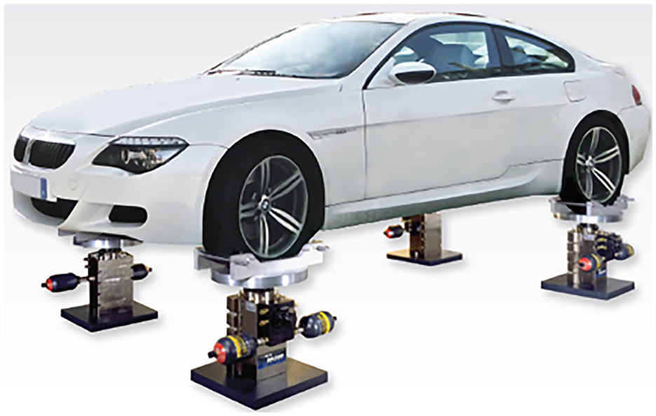
A 4-poster test rig (Team Corporation, 2014).
The processed road data are used as a reference signal of the control system. The control system of the 4-poster aims to track random road data, which is defined in a specific frequency band with minimum error. Due to the similarity of the control problem, the suggested methods both for 4-poster and other road simulators are considered together in literature. For the solution of the control problem, the model-based iterative learning control (ILC) algorithms are usually used. The ILC-based control methods are named as remote parameter control (Dodds, 1977), time waveform replication, and so forth, in industrial applications. In these methods, the linear model of the system is derived through system identification methods, and then by getting the mathematical model in frequency domain (Cuyper and Coppens, 1999; De Cuyper et al., 1998; Guan et al., 2015; Yanyan and Zhidong, 2016) or time-domain (Dursun and Bayram, 2012; Raath, 1993), the inverse model synthesis is produced. By modeling the relationship between the reference position of the cylinder and the desired control parameter, the system is controlled using the open loop inverse model controller. Tracking errors originating from modelling and inverting are reduced, by applying the inverse model in the ILC rule. Indeed, the underlying intention of the researchers is to decrease tracking error and increase ILC convergence speed. In De Cuyper (2006) and De Cuyper et al. (2000, 2003),
The primary motivation of this paper is to increase the convergence rate and improve tracking performance of ILC, which is used in 4-poster. In industrial applications, ILC is used as an offline process before testing to get accurate control performance. This process causes to increase test duration and cost. So, the literature of 4-poster control focuses on to increase the convergence rate and improve the tracking performance of ILC. When considering the nonlinear structure of the system, in the same way as Smolders et al. (2008), this study also starts with the assumption that producing a model inverse in a nonlinear structure would reduce the modeling errors. Additionally, it is esteemed that including other measured system parameters in the iteration process would further decrease the model-driven errors. Thus, we regard the system as a black box, since creating the system model analytically or as a grey-box would lead to practical matters, particularly for end-users. Differently from Eksteen, the system inverse is modeled by direct inverse identification via ANFIS, so there is no need for any inversion method. In order to incorporate the piston position to iteration, the system inverse is formed as a serial combination of two models. Through using the synthesized neuro-fuzzy inverse controller (NFIC) in the ILC rule, a controller synthesis is made for a double-layer neuro-fuzzy ILC (NFILC) by utilizing both the acceleration (i.e. the controlled parameter) and the auxiliary parameter (piston position).
This paper has two main contributions to the literature. Firstly, the nonlinear system dynamics are incorporated into the ILC rule by using a neuro-fuzzy inverse model of the system. Secondly, the double-layer ILC structure is built by adding the piston position to the ILC rule. Along with this, a double-layer NFILC is produced via iteration definition both for wheel acceleration and piston position, and neuro-fuzzy inverse controller (NFIC). We conduct extensive simulations that demonstrate that the proposed single-layer and double-layer NFILC structure outperforms the linear ILC.
The organization of the paper is as follows. Section 2 presents the system model and formulates the control problem. Section 3 discusses the general structure of ANFIS and the proposed identification method. Section 4 explains the control rule for the suggested control method, namely NFILC. Section 5 presents the numerical simulation of the suggested control method in comparison with the linear ILC. Finally, Section 6 discusses the outcomes of the study and concludes the paper.
Problem definition
In this section, we first introduce the mathematical model of the system and then formulate the control problem.
System modelling
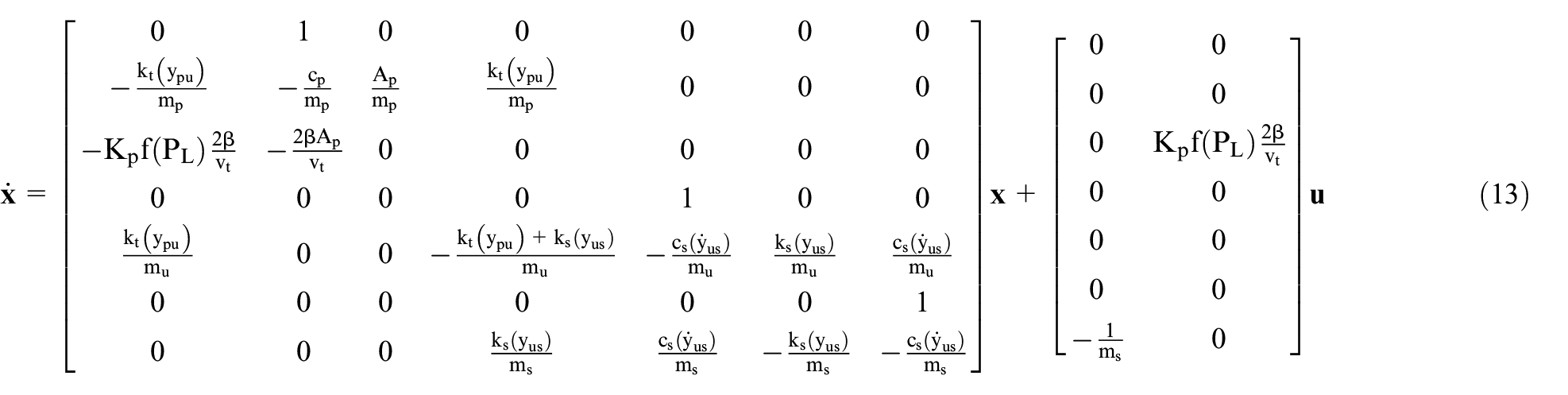
The 4-poster simulates the loads to which the vehicles are exposed while moving, through applying a load on the wheels. For a simplified model and control algorithm, just one hydraulic actuator and a quarter car model structure are used. The loads from the other wheels are considered as disturbances. The schematic representation of the system is provided in Figure 2. Hereupon, the term ‘system’ will cover the hydraulic cylinder and the quarter car system whose position is controlled with an input measurement on reference position signal and an output measurement on the wheels.

Schematic representation of the 4-poster.
The flow rate and the pressure required by the hydraulic cylinder are supplied through a hydraulic pump. It is assumed that the supply pressure
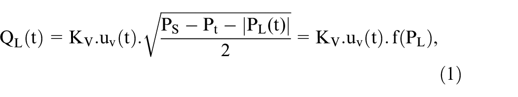
where
In the equation,

Note that


where


and


In these equations,

In here,
Control problem
As previously mentioned, the 4-poster aims to recreate acceleration and road data collected on land in a laboratory environment with the help of hydraulic cylinders. Thus, the vehicle is vibrated as if it is wheeling on the road, and one can monitor its performance in terms of fatigue and lifetime.
The control problem dealt with in this paper is essentially a trajectory-tracking problem. It is expected that the acceleration data obtained from the wheel of the vehicle,
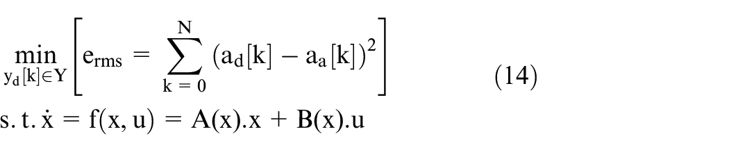
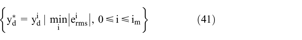
As can be seen from the definition of the problem, we deal with the error in the form of RMS (root mean square). By doing so, we would like to obtain the signal,
In literature, to solve this control problem, ILC is commonly used. As an offline control method, ILC is used to search the control signal, which provides a minimum tracking error of acceleration as much as possible before testing. Searching the control signal increase the necessary time for testing, so researchers focus on to increase the convergence speed of ILC to reduce the testing time. Therefore, in this study, the main motivation is to increase the convergence speed of ILC while keeping the error ratio minimum.
Neuro-fuzzy inverse system identification
The main issue in controlling the system is not to know the model. While some of the tested vehicle’s parameters are not known, and the ignored dynamics in the modeling phase bring additional disturbing effects. Also, additional dynamics arising from the non-ideal text fixture can affect the response of the system. On top of that, disturbances due to the dynamics of the actuator, which are not modeled and whose parametric values are not known further complicate the design. Besides, it is also essential to develop applicable algorithms for the 4-poster test system and to reduce the implementation costs of the test. A self-learning algorithm can address all the afore-listed issues; therefore, the system identification methods are widely used in controlling 4-poster. The inverse of the obtained model is used as the controller. In literature, the linear models are frequently employed for identification. Thanks to the ILC, the tracking errors arising from modeling and inverting are reduced to a certain extent. However, the nonlinearity of the real system increases the final error rate and minimizes the convergence speed. To sum up, the system’s inverse directly affects the performance of the ILC. In this study, the system inverse is obtained through ANFIS, and the nonlinear NFIC is formed.
Adaptive neuro-fuzzy inference system
In this section, the basic structure of the adaptive neuro-fuzzy inference system (ANFIS) is explained. For more info about applying ANFIS, please refer to Babuška (2003) and Jang (1993). Two rule structures for a fuzzy model with two inputs and one output are as follows
Rule 1: If x is
Rule 2: If x is
The network form for ANFIS in such an example is given in Figure 3. As can be seen in Figure 3, it consists of five sub-layers.
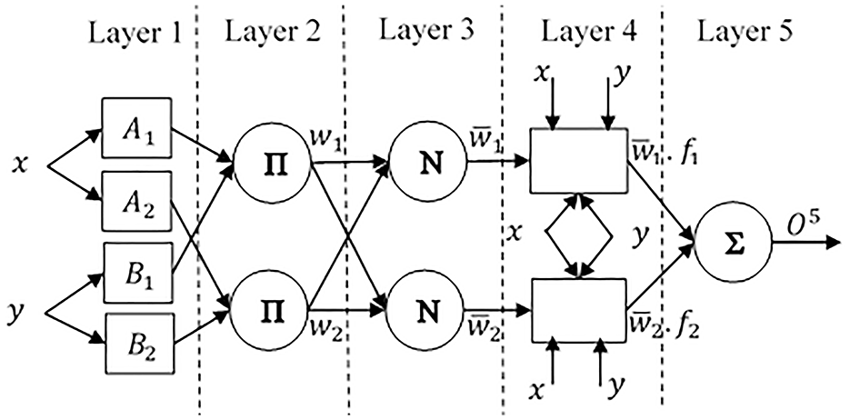
Network of ANFIS.
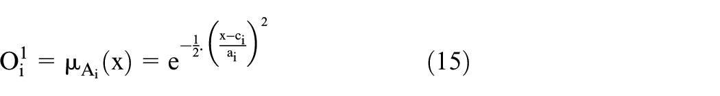
In Layer 1, the input variables are fuzzified with the help of a membership function. The output signal of the Layer 1 is provided in (15) for the Gaussian membership function.
In Layer 2, the firing strength values are built based on the membership values of the variables

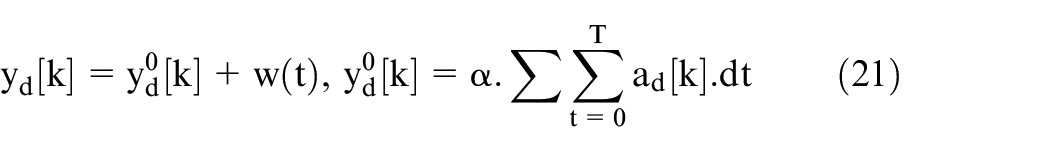
In Layer 3, the firing strength values are normalized
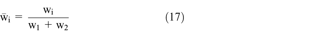
In Layer 4,

The summation node given in Layer 5 produces the model output by summing all values from nodes in Layer 4
The unknown parameters of the model, the parameters in the membership function of Layer 1, and the parameters of Layer 4 are provided below. The numerical values of the parameters are determined thanks to the learning algorithms based on input and output data (Jang, 1993)

Neuro-fuzzy inverse controller synthesis
In this section, the synthesis of the inverse model controller is discussed. The inverse controllers are used in solving various control problems. Especially in controlling high degree systems, due to difficulties of the controller synthesis, the inverse model controllers are preferred in the open-loop and closed-loop control systems. However, there are also several disadvantages obtaining a model inverse for the system whose mathematical model is produced through analytical or system identification methods. Because of the modeling errors, using the model inverse in closed-loop leads to stability problems. Due to zeros in the right half-plane, obtaining an unstable model inverse is one of the primary problems. Therefore, a suitable model inverting algorithm is needed. In Tomizuka (1987), for linear non-minimum phase systems, several inverting algorithms are recommended. Another method for model inverting is to determine the direct inverse of the system through system identification methods (Widrow and Plett, 1997). In these methods, system input is defined as system output by taking the real system output as the input of the identification process. Within the scope of this paper, ANFIS is used to obtain the nonlinear inverse model. In Ling et al. (2013), the rule definitions for open- and closed-loop ANFIS inverse control are made and applied to the nonlinear sample systems.
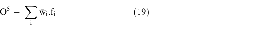
In this study, unlike model-based methods proposed for acceleration control of the 4-poster in literature, the inverse of the system is nonlinearly obtained through ANFIS. By forming two serial system models, both the performance of the identification is boosted, and the usage multi-layer ILC is allowed. The system to be modeled refers to the hydraulic cylinder and the vehicle whose positions are controlled. At this point, we assume that the system to be modeled is time-invariant, and does not change with iterations. During application, the acceleration of the wheel and the position of the hydraulic cylinder are measured on the system. The block diagram of the system identification is provided in Figure 4. The identification process is carried out for individual cylinders.
Block diagram of system identification.
In Figure 4,
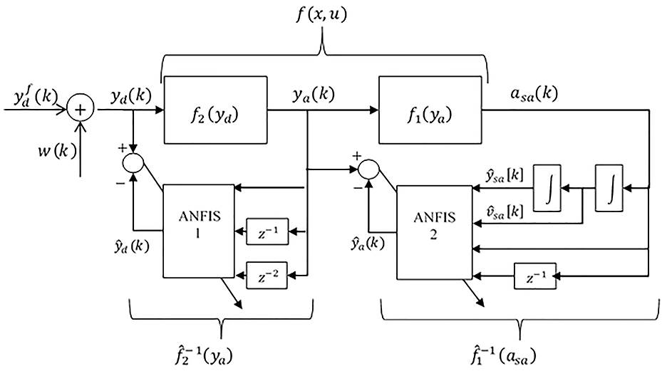
The system identification is performed through the ANFIS explained in the previous section. There are several aspects which should be responded by the designer/user in order to keep the input membership functions of the ANFIS within the domain. To produce the identification signal used for the excitation of the system, the acceleration-road data are handled through several processes provided in detail below. The proposed identification data
In this equation,
The system is excited. If condition
α is increased,
Upon forming
In the algorithm, while
By putting into the feedforward path as an open-loop controller, the NFIC is used in the ILC structure. In this way, the errors occurred due to modeling, and the serial subsystems approach is eliminated with the help of ILC.
Proposed control method
In this section, the proposed control algorithm is discussed. The NFIC obtained in the previous section is used in the model-based ILC rule. The ILC can be defined as an offline control method. The required control signal for enabling the system to track the desired trajectory is obtained upon several trials. The error signals received from the previous trial are used for improving the synthesized control signal; in other words, the experience transfer is ensured. Therefore, while the ILC is a close loop regarding performed iterations/trials, it provides an open control structure in the time domain (Xu and Tan, 2003). When the aimed tracking performance is achieved, the obtained control signal is used for continuing the system within the road simulation test.
The proposed control method has two original contributions to literature. Firstly, while existing ILC methods for 4-poster use the inverse of the linear model within the control rule, in this study, the nonlinear system identification is directly (without inverting) obtained by using the ANFIS and used within the control rule. Thus, the NFILC structure is formed. Secondly, the other original contribution of this study is to define a multi-layer ILC rule. In existing ILC algorithms for 4-poster, the system inverse is defined as a single model, and the ILC is applied for only sprung mass acceleration. However, in this study, the ILC rule is formed both for sprung mass acceleration and the position of the hydraulic cylinder. Thanks to these two contributions, the convergence speed of the ILC is increased. In the sub-sections, firstly, the proposed control rule is explained, and then the control system is probed in terms of stability and convergence.
Neuro-fuzzy iterative learning control
The proposed control model in this study includes the neuro-fuzzy model of the system inverse, as well as a multi-layer ILC structure. Obtaining the multi-layer models of the system allows forming a multi-structured ILC similarly.
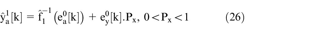
In the first iteration,
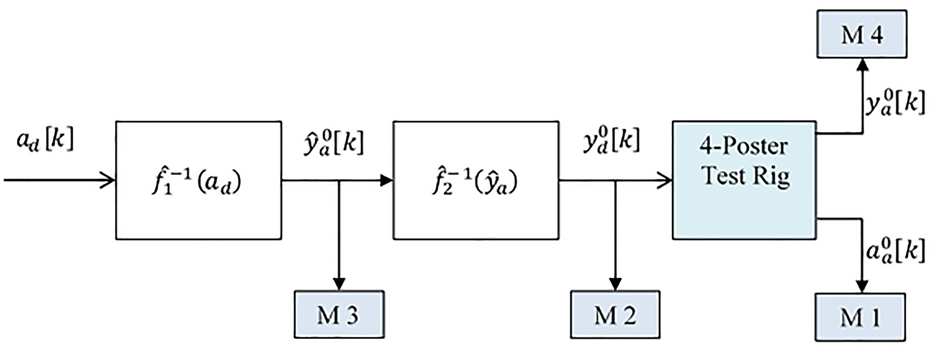
Control structure for i=0 (NFIC).
Control structure for i≥1 (NFILC).
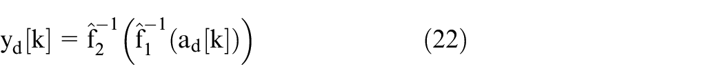
The control structure for the first iteration is as follows
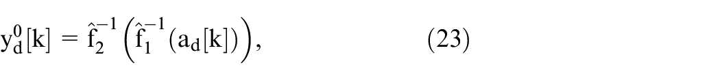
and it has an open-loop NFIC structure. As explained in the modeling phase, the effects from other actuators are considered as disturbances in this study. The reference position signal obtained from the NFIC output is not an ideal input for the controller. In order to eliminate both the modeling errors and errors due to disturbances, an iterative improvement process is applied. At this point, two error signals should be defined for producing a two-layer ILC structure. The first error signal is the error definition between the road map and the measured acceleration data of the sprung mass. Indeed, the primary aim of the control system is to minimize this error. The error signal of the acceleration,

The second error signal is referred to as the estimated position value and the measured position value of the hydraulic cylinder. In this paper, in addition to the model-based ILC algorithms regarding 4-poster control in literature, the position error value is defined within the ILC rule. The error signal of the position,

After the inverse model control process, it is proceeded with the iteration phase by using the saved data. The reference position signal of the hydraulic cylinder which minimizes the acceleration tracking error,
The
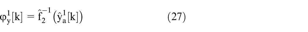
The obtained reference position signal from the previous iteration,

The

The estimation error,

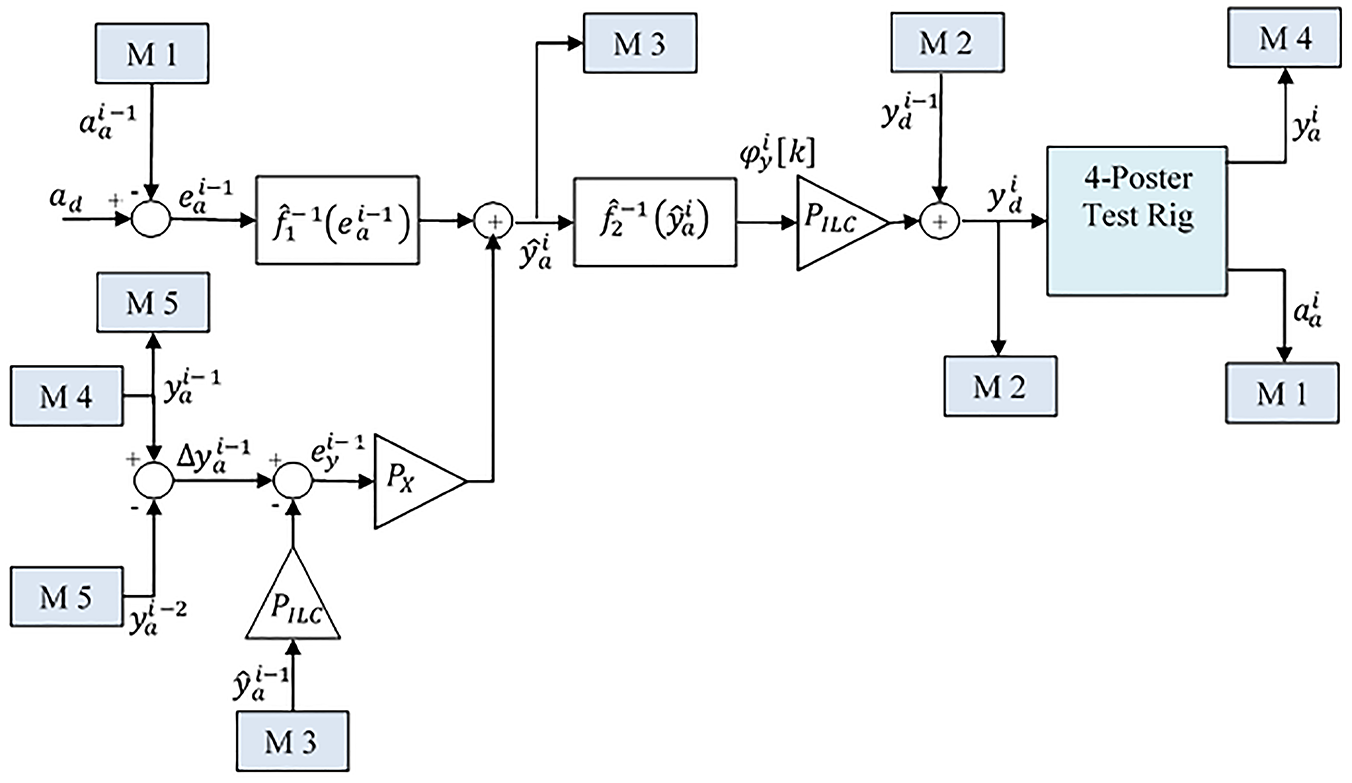
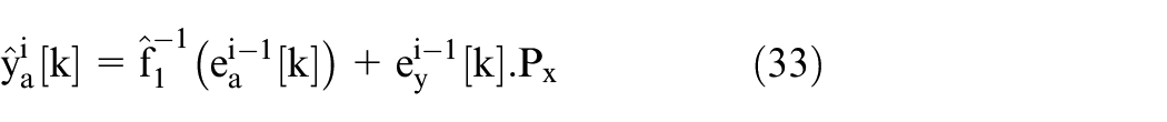
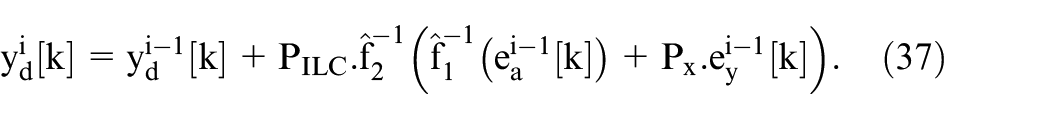
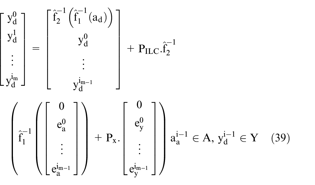
The double-layer NFILC control structure is for all following iterations (i.e.
The error expressions used in the control rule for every iteration are re-revised and transformed as below


The position estimation value, change in position measurement and the reference change value is re-written as

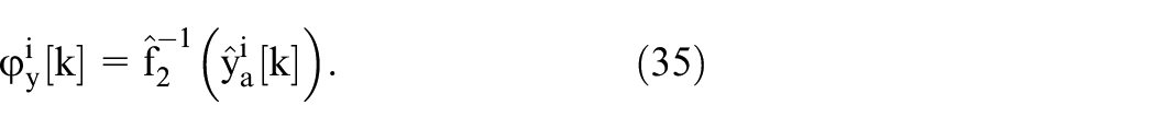
On the iteration domain, the closed-form generalized control rule is as below

Which can also be expressed as
In each iteration, which is used to determine the acceleration control performance (
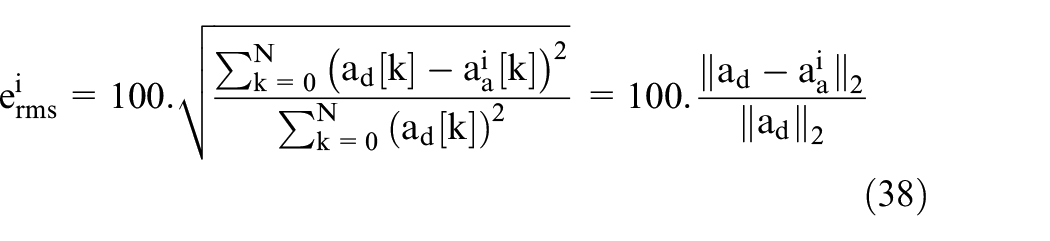
The iterations are terminated when the error rate drops below a pre-defined rate or when the (user-defined) maximal number of iterations,
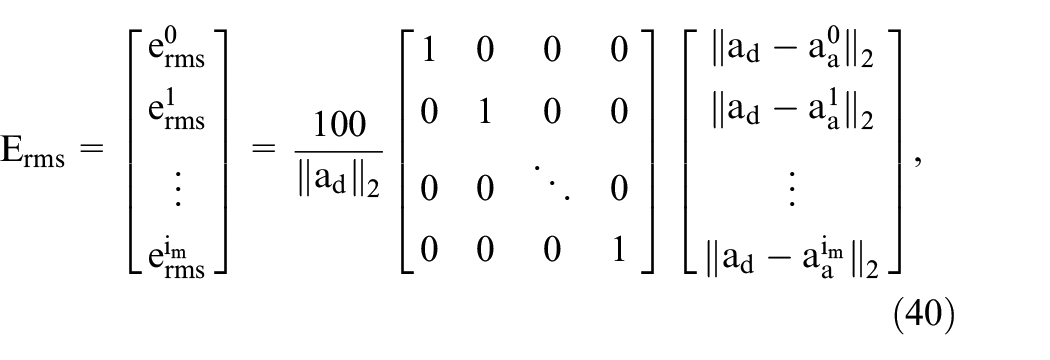
The resulted error rate vector during iteration can be produced as below
Stability and convergence
For stability, the system should be assessed at the step of the feedback position control. For a P-type controller developed for the position control and expressed in (12), it is enough to keep a closed-loop system stable in terms of Lyapunov stability. In literature, researchers do not focus on the stability and performance of position control, which is qualified as a suboptimal problem (De Cuyper, 2006). The most important part of the overall control algorithm is acceleration control via ILC. Thus, the main issue analyzed in literature is the convergence of ILC because of its offline structure.
As an optimization problem, convergence is a highly studied aspect for ILC (Chen and Wen, 1999). For a stable inverse model control structure (
The error-rate minimizing reference position signal can be used for testing the vehicle. If the control system achieves a monotonic convergence, it can be implied that the (sub)optimal reference position signal is
Simulation
In this section, the proposed control algorithm is tested on the Simulink® model prepared with the mathematical model of the system, and the relevant results are presented. The proposed linear ILC in literature is compared with three output performances, using single-layer and multi-layer NFILC methods proposed in this paper.
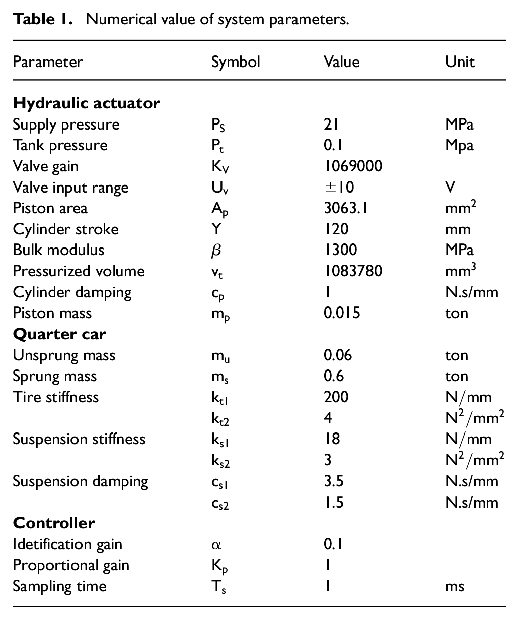
The numerical simulation is created by using the mathematical model of the system detailed in Section 2, and defining the valve actuator dynamics neglected in the model, the compressibility effect of the hydraulic oil, the input, and state saturations. Here, the hydraulic actuator parameters that are used are produced by validating with the real system (Dursun and Bayram, 2012). For some parameters that pertain to the quarter vehicle model, (Du et al., 2012) is referred. As a result, the parameters of the model used in the numerical simulation are provided in Table 1.
Numerical value of system parameters.
Being considered as the reference signal of the control system, the road data
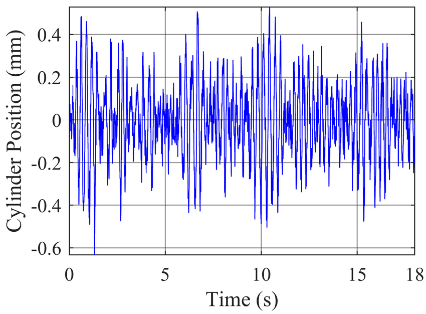
Excitation signal for system identification.
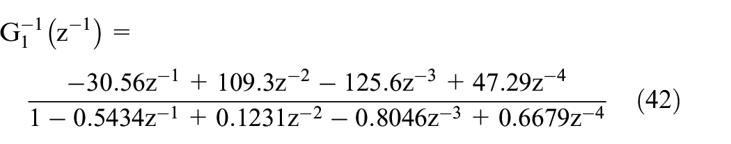
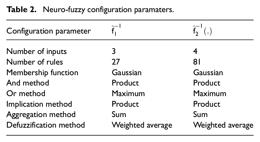
Upon applying the excitation signal to the system input, the obtained data at the output are modeled through the MATLAB®anfis function. The important aspect which should be noted in system identification is that the input and the output of the ANFIS consist of the system output and the system input respectively. Thus, the direct inverse identification is performed. In order to fuzzify the input variables of the neuro-fuzzy models, gaussian type membership functions are selected. The two obtained models are used within the
Neuro-fuzzy configuration paramaters.
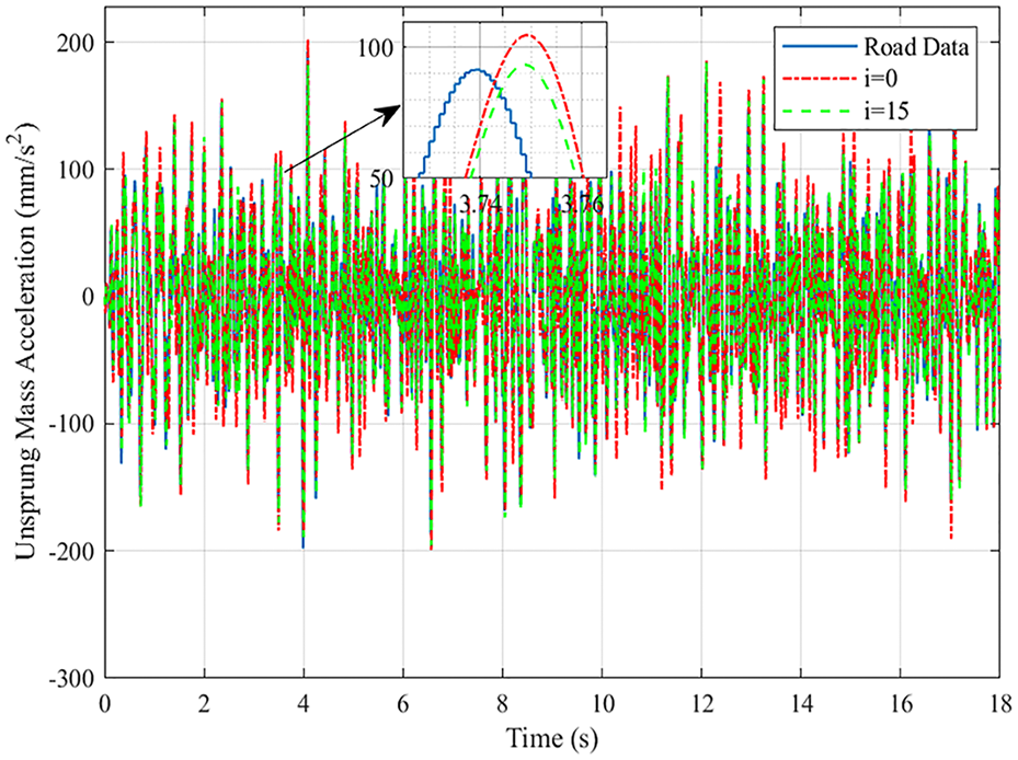
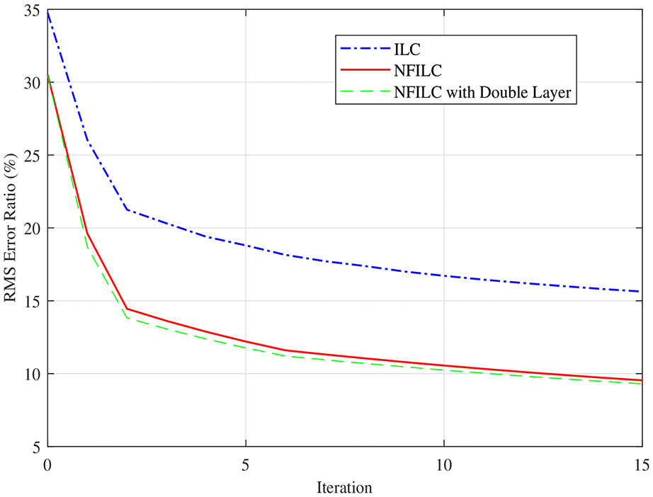
In the first test, simulations are conducted on a single axis, namely without disturbances. In the first simulation, the ILC layer created for position estimation is eliminated by setting
Acceleration control performance- 1.
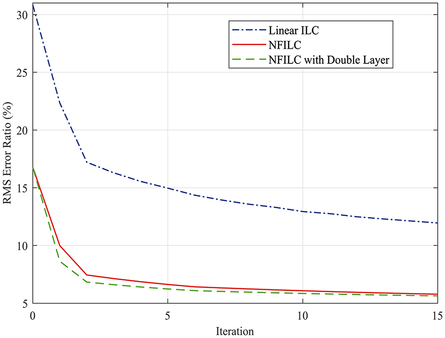
Changing of error ratio with iteration- 1.
In the second test, the disturbance input of the dynamics which emerges from the other axes of the 4-poster is given as
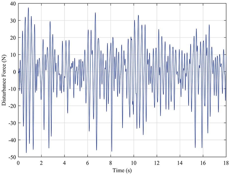
Disturbance input.
Under the effect of the disturbance input, all simulations are repeated similarly with the first test. The graphs of the change in acceleration and the iteration-dependent error rate resulted from the second test are given in Figure 11 and Figure 12.
Acceleration control performance with disturbance input.
Changing of error ratio with iteration- 2.
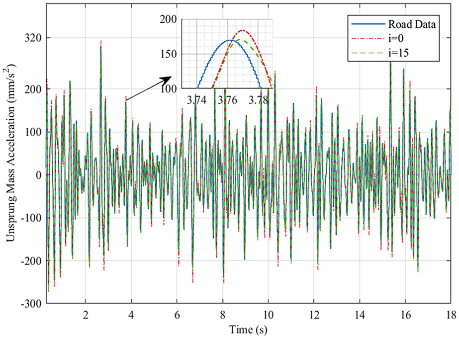
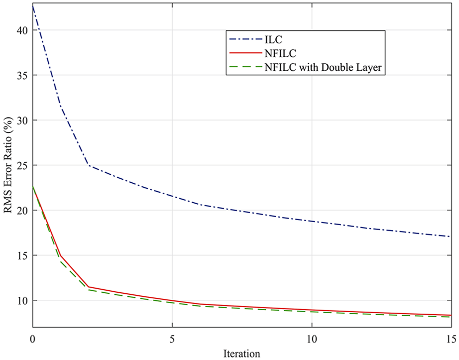
In the third test, it is assumed that the vehicle is linearly accelerated 0 to 100 km/h in order to test the performance of the proposed method for varying vehicle speed. In addition to that, the disturbance input given in Figure 10 is used again to simulate the effects of other wheels. Under these conditions, all simulations are repeated with the same settings of previous tests. The control performance of the proposed method for the third test is given in Figure 13 and Figure 14.
Acceleration control performance with disturbance input and varying speed.
Changing of error ratio with iteration- 3.
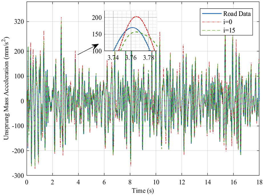
It can be observed from Figure 9, Figure 12 and Figure 14 that the control algorithm increases its trajectory-tracking performance along with the iteration increment. In comparison with the first test, under the effect of disturbance input, the error rates and the convergence speeds decrease as expected. In the third test, under disturbance and varying speed conditions, the algorithm is still effective on convergence speed comparatively with conventional ILC.
The difference between the first error rates is related to the inverse model control performance. Here, the performance difference between NFIC and LIC can be seen. In the first test, the obtained error rates of NFIC and LIC for
Another critical point observed from the tests is that ANFIS needs a long-time duration to process the signals. As mentioned before control method has online and offline parts. The online component of the algorithm includes a PID type feedback controller, which satisfies closed-loop sampling time (
Conclusion
In this paper, a single- and double-layer NFILC is proposed instead of the linear model-based ILC, which is widely used for 4-poster control in literature. In order to obtain an appropriate inverse model for a multilayer ILC, multiple models of the system are created through ANFIS by considering a system model consists of two serial-connected sub-models. Then, it is applied to the Neuro-Fuzzy Inverse Controller ILC rule. The double-layer ILC structure is built by using the piston position in ILC. As a result of two tests based on a simulation, it is observed that two proposed control methods in the paper produce better outcomes than the linear ILC. Also, the inverse model controller created through ANFIS reflects the nonlinear dynamics of the system much better. Along with that, when the NFILC structure is turned into a double-layer structure, the final error rate and the convergence speed perform better.
Nonetheless, the assessed control method in the paper is open to further improvements. Bringing a MIMO structure to this control algorithm in a similar manner to Vaes et al. (2002) would improve the convergence speed of the ILC. Besides, an increase in the number of the measured system state and the inverse model control structure serially built between these states would increase the number of the auxiliary parameters that can be used within the ILC. Thus, a further increase in the convergence speed of the ILC is expected. It is thought that creating an adaptive structure similar to Moten et al. (2015) would be appropriate for tracking the changes in the model during iterations. To increase convergence speed and to maintain a monotonic convergence, forming the coefficients
Footnotes
Declaration of conflicting interests
The author(s) declared no potential conflicts of interest with respect to the research, authorship, and/or publication of this article.
Funding
The author(s) received no financial support for the research, authorship, and/or publication of this article.