
Abstract
Multi-vector arrangement is a novel propulsion architecture for remotely operated vehicles (ROV) because of its high manoeuvrability and efficiency, but the influence on the ROV dynamics and attitude servo control has not yet been clearly evaluated. This study fully investigated the kinematic behaviours of a hexagonal multi-vector propulsion ROV with communication delay constraint and reduced the complex model for precision control system design. An enhanced model-based PI robust controller (EMPRC) based on the nominal model is proposed to solve the nonlinear hydrodynamics and communication problems with high performance yaw control, whose stability is also analysed. The conventional proportional-integral-derivative (PID) and integral separation PID are used in the experiments for comparison. The results indicate that the proposed EMPRC can effectively track the desired attitude and reject the external disturbances, while the conventional ones are limited by the nonlinear dynamics and communication delays. The improvement is 3x on average in terms of overshoot, settling time and anti-disturbance recovery time compared to conventional algorithms and proves this proposed novel EMPRC is a practical solution for multi-vector propulsion ROVs.
Introduction
Discovering and developing the oceans have become vital strategies for many coastal countries in the world to expand the horizon (García-Valdovinos et al., 2014)), since the ocean covers
The attitude control is a vital issue for ROVs since a steady attitude is highly recommended for many scenarios such as underwater oil pipeline inspection and seabed equipment maintenance (Sahu and Subudhi, 2017; Wu et al., 2019). This is very challenging, because ROVs typically travel in complicated ocean environments with time-varying and uneven currents (Fan and Woolsey, 2013). Within this extreme underwater nonlinear environment, it is critical to design a vehicle that adapts to a nonlinear environment (Vlahakis and Halikias, 2019).
The control system design approach tends to be an effective shortcut to improve the performance without modifying the hardware (Eidsvik and Schjlberg, 2016; Li et al., 2017). For any attitude control task, the first solution that comes to mind would be the proportional-integral-derivative (PID), which has advantages of high efficiency, small computation load and easy debugging for engineers. However, the conventional PID failed to meet the specifications of high-performance ROV attitude control because of the nonlinear hydrodynamics, and scholars proposed an advanced PID-type controller to overcome this issue. An experimental comparative performance of a PD controller and a nonlinear feedback adaptive algorithm to regulate the depth of an autonomous underwater vehicle (AUV) was presented in Maalouf et al. (2013). Bijani and Khosravi (2018) presented a new strategy for tuning the coefficients of a PID controller regarding
Other than PID-like methods, other controllers have been investigated, such as robust adaptive PID, adaptive control, sliding mode, etc. (Javadi-Moghaddam and Bagheri, 2010); Li et al., 2012; Molero et al., 2011). A systematically MIMO nonlinear robust controller designed based on adaptive backstepping technique and sliding mode control for ROV was introduced by Zhu and Gu (2011). Campos et al. (2017) accomplished two nonlinear controllers based on saturation functions with varying parameters for ROV with good experimental validation. Methodology designed for ROVs by Medina et al. (2016) and the design simulation was evaluated to reduce undesirable effect of the sliding mode chattering for ROV.
Intelligent control systems for ROVs have also attracted the attention of academia, which is advanced by the developed computer and instrumentation technology. Neural networks with PID were investigated in vehicles and nonlinear systems (Marzbanrad et al., 2011; Song et al., 2011) and the intelligent systems were mainly used as online parameter adjustment (Hernández-Alvarado et al., 2016)). The thoughts of intelligent controllers can be summarized as using an online data-driven policy to optimize the control variables. However, the stability of these methods is difficult to guarantee in the complex environment and the computational costs (time and power) are not affordable in the real ROV applications.
The influence of communication time delay characteristics has caused more complexity in identification (Sarhadi et al., 2015).
Structure and hardware design are other important factors for attitude control. There is usually a engineering trade-off between the attitude stability and the manoeuvrability. Multi-vector propulsion arrangement is becoming popular in lightweight ROVs since over-actuated engines provide more power, which can potentially avoid disturbances without decreasing manoeuvrability, but so far, few engineers have fully taken advantage of it. An undesired crucial limiting factor that is usually overlooked in ROV control systems is the communication delay. The fundamental electronics such as microprocessors, data converters and power electronics are typically placed in a well-sealed container with few communication connectors. Frequently programming and debugging the microprocessor is not economical. So implementing the advanced control algorithm in the remote PC side and the microprocessor only reserved for the basic propeller operations would be a common choice, especially if the researchers want to prototype a variety of control algorithms. In this case, the communication delay between the ROV and PC becomes very serious, considering the length of the connection cable can is at the 100-metre level.
Based on the above discussions, we identified that investigating the dynamics of the multi-vector propulsion ROV with communication delay and establishing a practical yaw servo control system can contribute both to the industry and to academia. The validation platform is a lightweight ROV with multi-vector propulsion arrangement designed and manufactured by Ocean University of China.
The contributions of this paper are summarized as follows:
This paper first proposes a comprehensive architecture that takes advantage of multi-vector propulsion arrangement mechanism and its cooperated EMPRC controller to provide improved attitude tracking and anti-disturbance capability.
A practical kinematic model of the multi-vector propulsion arrangement driving system with communication delay is first established. It initiates with the hydrodynamics of the ROV, then proves the nonlinearity cancellation effect by using the multi-propulsion design that improves the inherent motional performance with a time delay factor. The residual non-ideal factors under this hardware configuration are discussed for the control system design.
The EMPRC is designed to cooperate with this unique driving system and optimized for the residual non-ideal components. It describes the system with a nominal model obtained by system identification underwater experiments and a residual hydrodynamic error term. An optimized control law includes the variable gain PI component and robust terms is proposed and analysed to meet the high performance tracking and anti-disturbance requirement.
The enhancement of EMPRC is validated experimentally by comparing with the conventional PID controller and integral-separation PID controller. The results demonstrate that the key metrics have been improved by 3x on average. In detail, the overshoot of EMPRC is reduced by
Establishment of ROV dynamics model
Analysis of the overall structure of ROV
An open-frame ROV is utilized for experimental analysis in this paper, in which the propellers are multi-vector arranged. One of our aims is to study the advantages of vector symmetric polyhedron mechanical structure for vehicles in dealing with nonlinear environments. In this vein, we first propose and design a ROV with the mechanical structure of vector-symmetric hexagonal. In addition, the excellent performance of ROVer’s mechanical structure is constantly reflected in actual yaw tracking experiments underwater. To further research yaw angle motion of ROVer, this paper first derives the motion equation of ROVer on the horizontal surface. According to Society of Naval Architects and Marine Engineers (SNAME), the static coordinate system
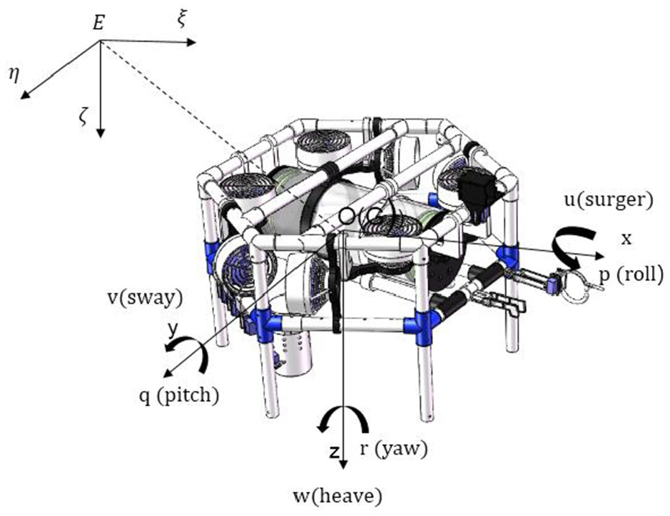
The vehicle ROVer, with the static and dynamic coordinate system.
The static coordinate system is based on a point on water surface as the origin. As shown in Figure 1,

where

The force and moment vector is
ROVer is actuated by eight propellers for roll, pitch and yaw, and the propellers of that distribution diagram are shown in Figure 2. Four horizontal propellers (T1 to T4) are utilized to control yaw. Undesired interference factors can be mitigated by ROVer’s multi-vector propulsion device with a hexagonal three-dimensional space structure. The linear velocity of the horizontal plane in
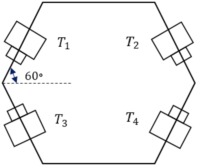
Propellers distribution diagram of ROVer.
ROVer’s propellers thrust (moment) vector
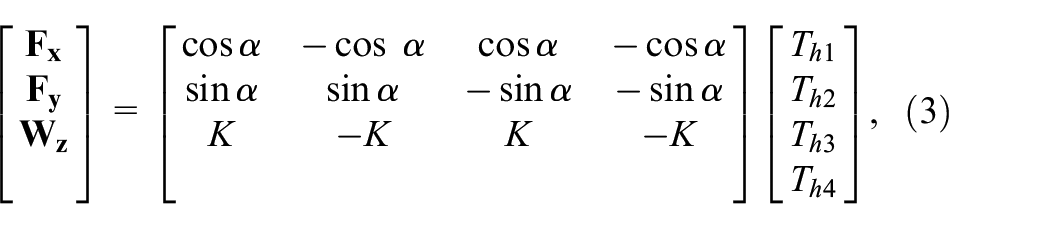
where
Dynamics analysis of the yaw by multi-vector propulsion solution
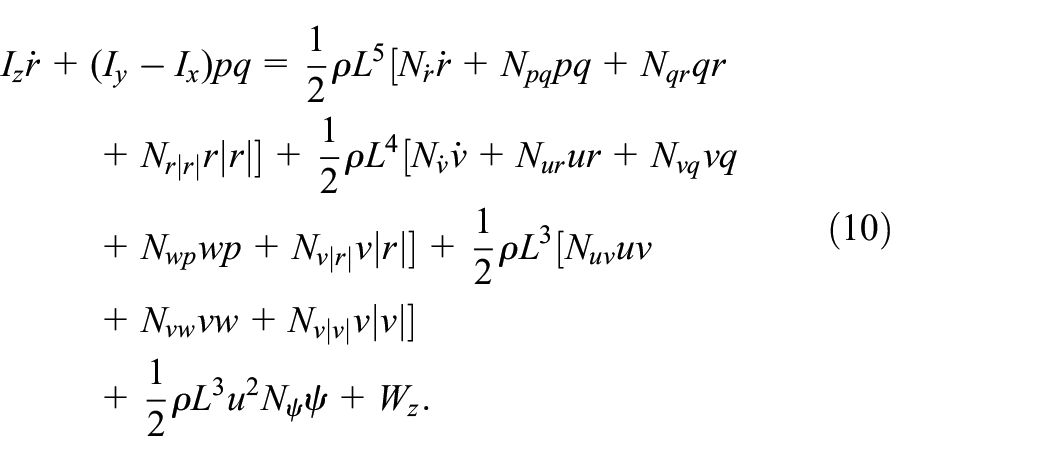
The six degrees-of-freedom (DOF) equation of motion for vehicle is actually cross-coupled. Intuitively, the movement of each degree of freedom is not isolated but related to several other degrees of freedom. Complex kinematic equations are one of the obstacles to the precise control of ROV (Rezazadegan et al., 2015) and can be solved by decomposing or simplifying the system. Assuming the vehicle’s depth is constant and the change in heading makes the centre of gravity for ROV always on the horizontal plane, the coupling of horizontal and vertical plane degrees of freedom is ignored to decompose the horizontal motion of ROVer. The equation of motion on the horizontal plane is expressed as:
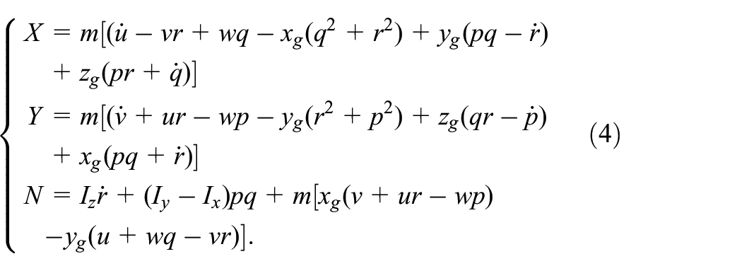
ROVer’s position in dynamic coordinate system is represented by
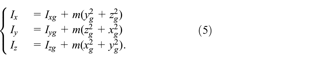
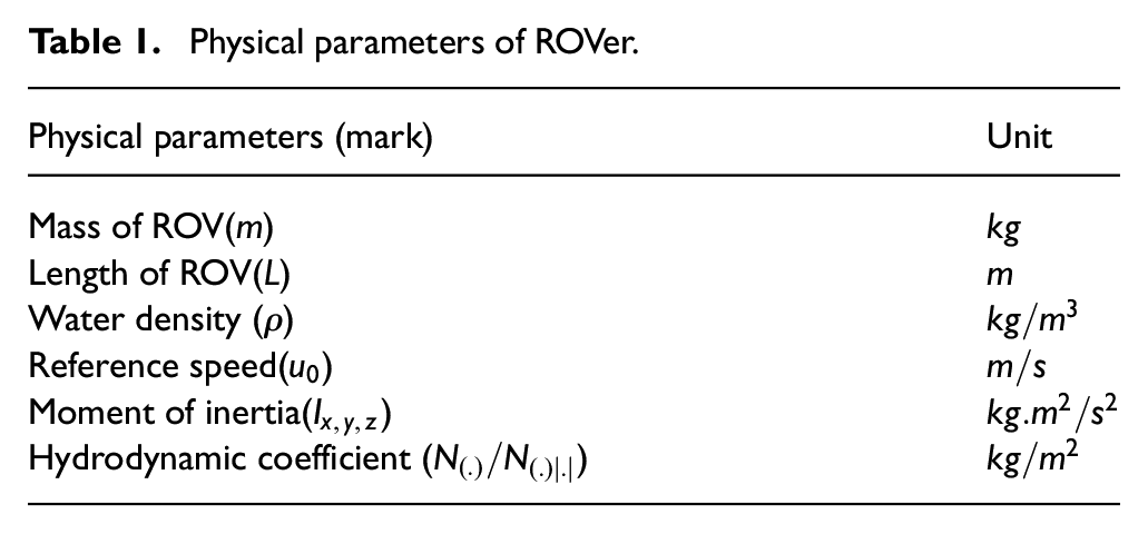
The physical model parameters and hydrodynamic parameters are listed in Table 1.
Physical parameters of ROVer.
Focusing on ROVer’s yaw control, we ignore the role of coriolis force. Ignore the effects of the off-diagonal elements of ROV’s matrix inertia tensor and the motion of the swaying degrees of freedom.

To calculate the additional mass and the linear dynamic damping coefficient matrix of ROVer, we utilize computational fluid dynamics (CFD) method to calculate hydrodynamic damping coefficient about yaw control. Consider the motion of ROVer in rotation mode and calculate the rotational damping moment. As shown in Figure 3, watershed I is the internal rotating watershed, and sub-watersheds II, III, IV and V are external static watersheds. ROVer’s length is
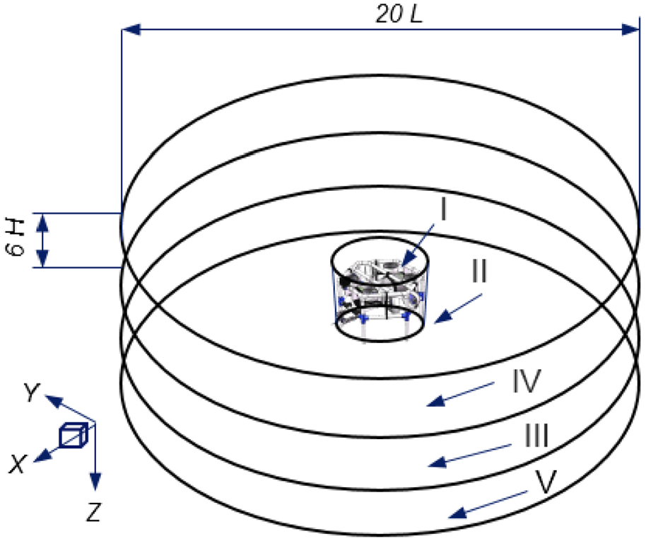
Structure of yaw rotation calculation domain.
The fitting relationship between the damping force and moment of yaw rotation is:

where
The coordinate conversion relationship between the angular velocity in the ROV dynamic coordinate system and the static coordinate system is:
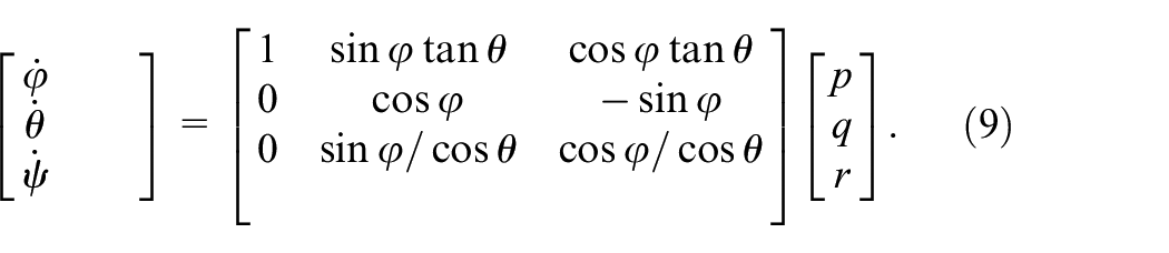
The relationship between
According to arrangement of propellers on ROVer, the residual linear velocity generated by course control of propeller is negligible when the speed is small in the experiment. i.e.
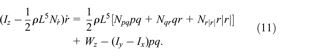
Obviously, incomplete equilibrium will inevitably occur during the movement. Angular velocities

The transmission mechanism is typically done through a cable and results in a time delay

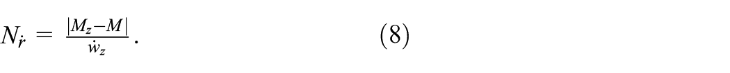
Based on the above, we select
The nonlinear damping
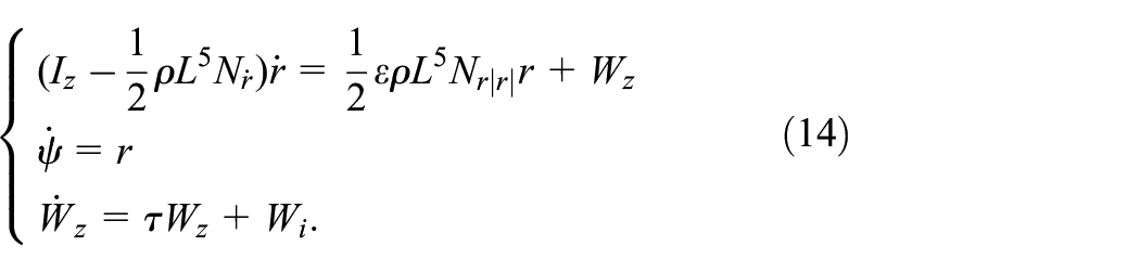
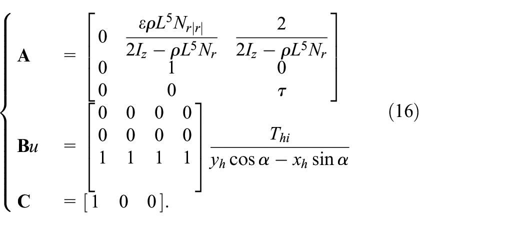
For small dynamic linear (12), PID can play an effective control role. It is difficult for PID to achieve the control requirements of accurate and fast when the speed of the ROV is too fast or the external interference is too large. The model of ROVer can be built as a standard state space model:
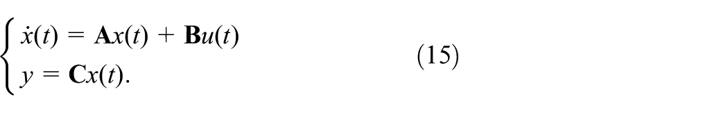
Observation vector
With nonlinear enhancement of system under large dynamics, it is difficult to achieve stable and reliable control of PID for ROV. The multi-vector propulsion arrangement of ROV makes the system more stable and offsets some of the unknown forces. However, it is not enough to rely solely on mechanical mechanisms to achieve excellent control performance. The design of a stable and efficient controller is essential.
Control system design
Three control methods are utilized for yaw tracking. These methods are described in this section. For the horizontal motion of ROVer, two state variables are our main consideration, yaw
Classical PID controller
PID’s control law can be expressed in following basic form (Astrom 2005):

where
Integral separation PID controller
The purpose of introducing the integral link in PID is mainly to eliminate static difference and improve precision. However, during the period of tracking of yaw in the beginning or when there is a large disturbance in environment, accumulation of a large amount of angular errors generated in a short time causes the output to overshoot, which damages the propeller. The specific implementation steps of integral separation PID are as follows:
Reasonably set the value
When
When
The control law of integral separation PID is as follows:
where
Enhanced model-based PI robust controller
According to models (14) and (15), the system is further described as follows:
where the state variabls are
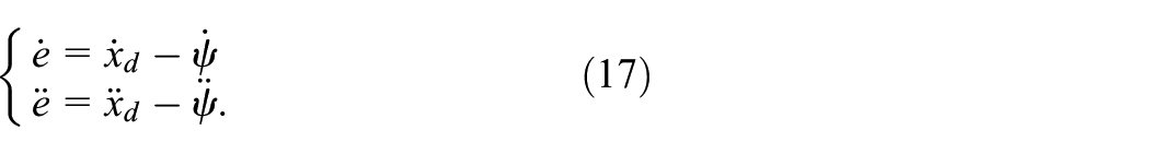
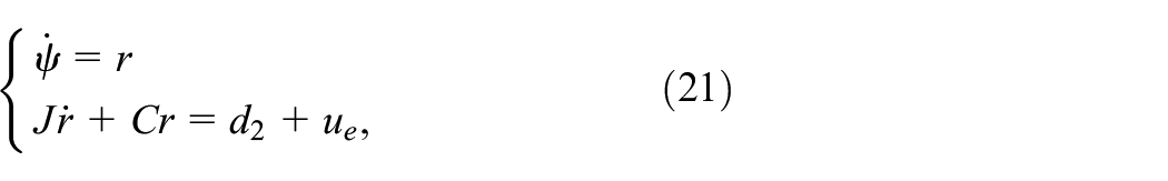
We define error function
Derived from (21).

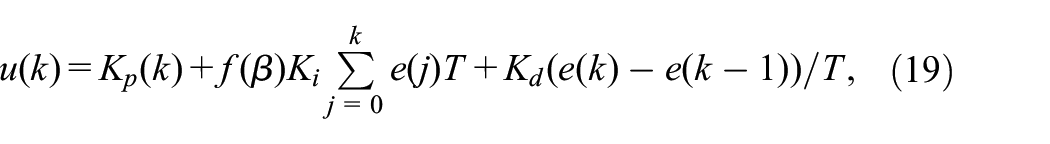
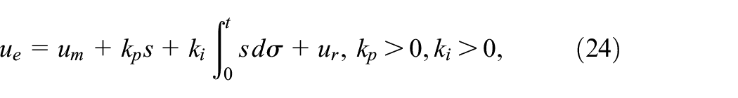
According to model-based PI robust control method, control law is designed as:
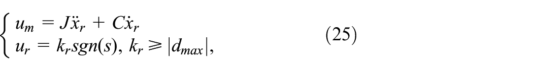
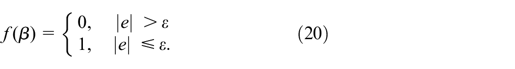
Through a large number of experiments, we have summed up an effective experience that system control parameters should be proportional to real error, which improves the anti-disturbance. We have established a function in control system for precise control on ROVer. The formula is expressed as
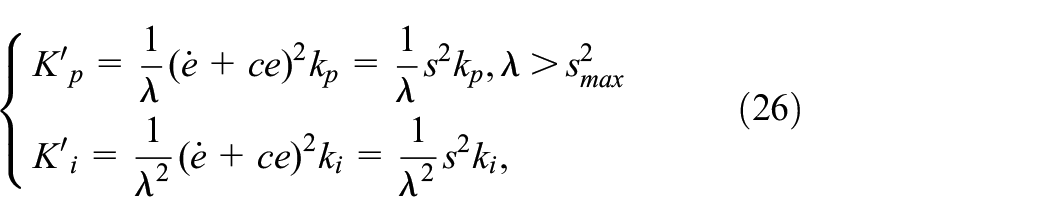
where
Combining with (24) and (26), EMPRC’s control law can be expressed as:
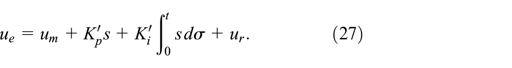
Where
Combine (21) with (25):
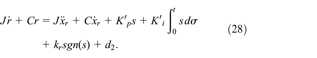
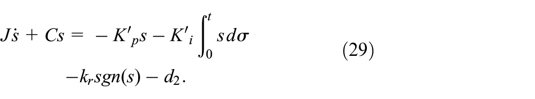
We further reduce (28) to get (29)
Stability analysis
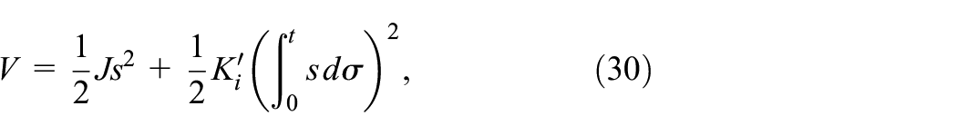
According to the control law (27), we take the Lyapunov function as
then
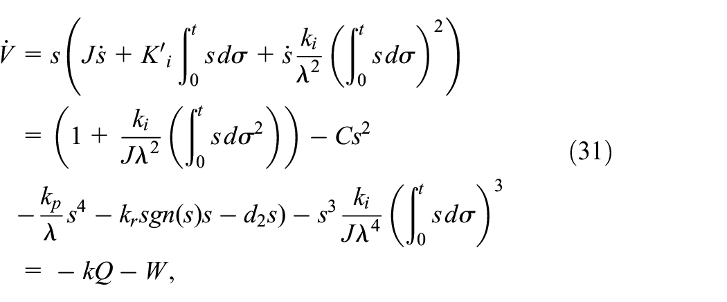
where
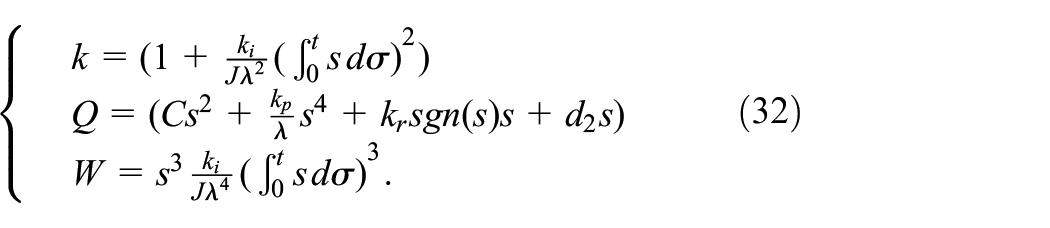
The analysis by summarizing (31) is as follows:
For
For
For
Using a strict Lyapunov function to prove stability of a closed-loop control system is critical (Li et al., 2019)). In summary,
Experiments
In this section, we present experimental comparisons of controllers. All pool experiments in this paper were performed inside Ocean University of China. The proposed EMPRC is compared with integral separation PID and PID to validate its performance and feasibility.
Hardware platform
The self-developed ROV has a portable, expanded modular structure, whose size is
As shown in Figure 4, the complete control system of ROV consists of five layers. The display layer refers to human-computer interaction interface, including underwater image and visualization status, etc. The management layer refers to monitoring of various states. The role of the task layer is more prominent, which includes control algorithms, system parameter configuration, data storage and other specific operations. The purpose of the data processing layer is to analyse communication packets and generation protocols between host computer and vehicle. All the data information and control commands obtained by the controller are transmitted at a frequency of 10 Hz between the host computer and the ROV through power carrier communication.
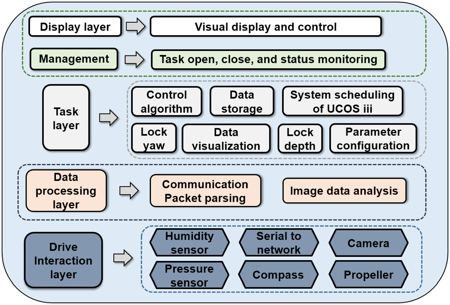
System block diagram of ROV.
The type of propeller arrangement is divided into vertical and horizontal, which completes six degrees of freedom of motion. The 45-degree tilting placement on horizontal propellers mitigates the effects of unknown forces. The internal driver of the propeller is a brushless motor controlled by pulse width modulation (PWM). The control amount calculated by the controller is converted to a motor identifiable signal and transmitted to the vehicle. The actual control signal of electronic speed control (ESC) of brushless motor is input signal of Figure 7 plus 1500 – the propeller does not work when the PWM is 1500. Figure 5 shows the vehicle that is conducting a yaw tracking experiment in the pool.
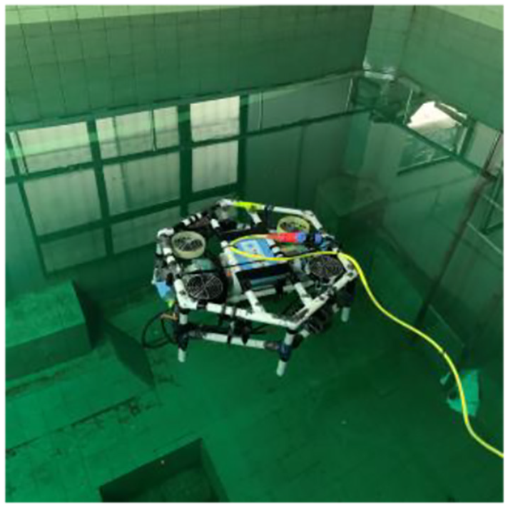
Experiment of yaw tracking in the pool.
System identification
Our purpose of identification experiment is not only to verify model derivation of ROV, but also to obtain a nominal model for control algorithm to further design. To better obtain the reference model which is closer to the actual ROV’s model, we performed a number of pool experiments on it. System identification helps to deal with complex systems that are difficult for us to analyse (Ljung, 2001). In recent years, system identification is applied in many experimental processes and performed by calculating the vehicle’s start-up response process and comparing control signal with actual output. The steps for system identification implementation are as follows:
Providing a variety of sine wave control signals at different frequencies to stimulate the vehicle. No human commands and remote control operations are applied to ensure the system identification accuracy.
Recording the input/output signals of the vehicle and generating a data matrix that includes time stamp, input signals and yaw.
Exporting the data for system identification.
The input and output data obtained in the experiment are shown in Figure 6. The details of state space equation of the reference model are described by the following:

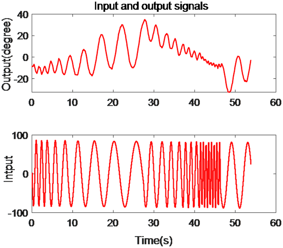
Experimental data for system identification.
Experimental comparison
In this section, five experiments were designed, including four different yaw tracking and a disturbance experiment. To comprehensively study the relative performance of control algorithms, the conventional PID, integral separation PID and the proposed EMPRC were evaluated in these tests. As the linear nominal model had been already established, the conventional PID was tuned by the MATLAB PID tuner. The well-known Ziegler–Nichols method was borrowed to provide a fair parameter configuration for the separation integral PI to do the comparison (Mudi and Pal, 1999). The key practical indicators are overshoot and settling time. The pool is inside the building to prevent the possible influence of wind.
As discussed in the previous sections, the nonlinear factors are coupled with travelling angle. To prove the above statement, we set a small range yaw (50º) in the first experiment and increased the desired angle to 200º with a step of 50º gradually. The procedure of experiment is as follows:
Turn on the automatic control mode, which is tracking the yaw through the internal controller, where the set angle of yaw is changed online by the host computer.
Change the setting angle to 0º.
Real-time observation and recording of all states of ROV through the upper computer display interface.
The tracking set time is 20s. After ensuring that there is no external environmental influence, wait for water flow to stabilize, then repeat the steps for the next experiment.
As shown in Figure 7, the EMPRC shows the good performance compared to conventional PID and integral separation PID. The EMPRC has no overshoot and the settling time is only 0.5s slower than integral separation PID. The PID has an overshoot of
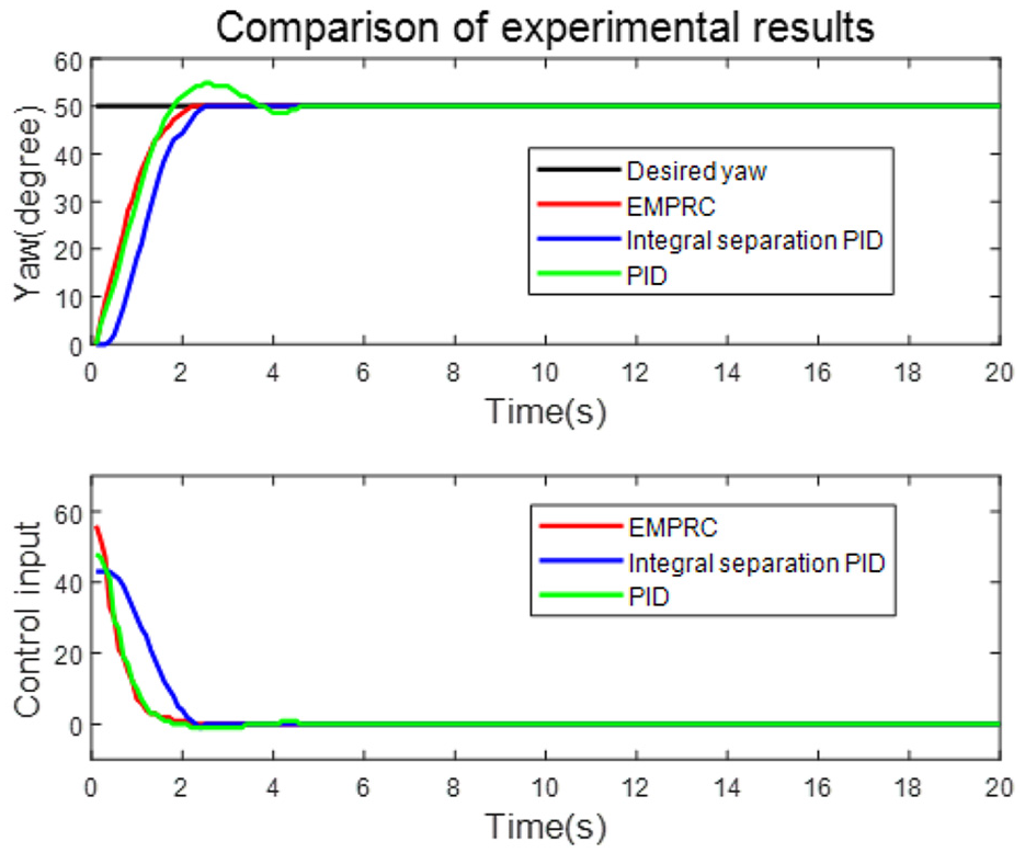
Comparison of yaw (50º) tracking experiments.
As shown in Figure 8, EMPRC is beginning to fully show its advantage in having the fastest settling time without obvious overshoot.
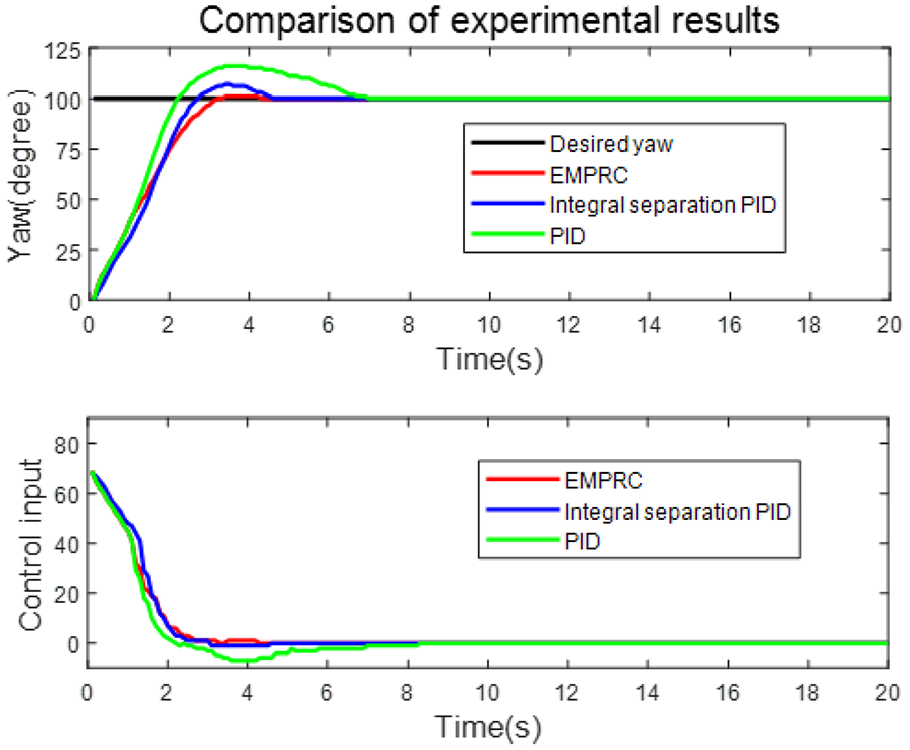
Comparison of yaw (100º) tracking experiments.
The third test has a desired tracked yaw of to 150º. Experimental comparison is shown in Figure 9. The third experiment highlights the advantages of EMPRC. As the travelling angle increases, the nonlinearity of the underwater environment was becoming significant. The response of conventional PID shows both an overshoot and oscillation manner with a very long settling time of more than
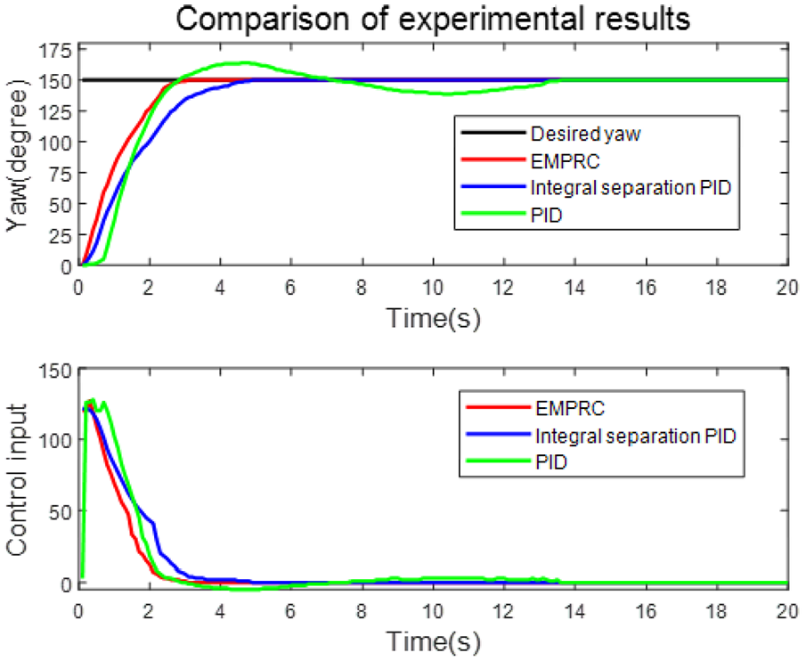
Comparison of yaw (150º) tracking experiments.
To further investigate the performance of the three controllers, the yaw set point was increased to 200º in the fourth experiment, the results of which are shown in Figure 10. The abnormal trajectory of PID is due to the communication delay and the nonlinear hydrodynamics of the system with a nearly
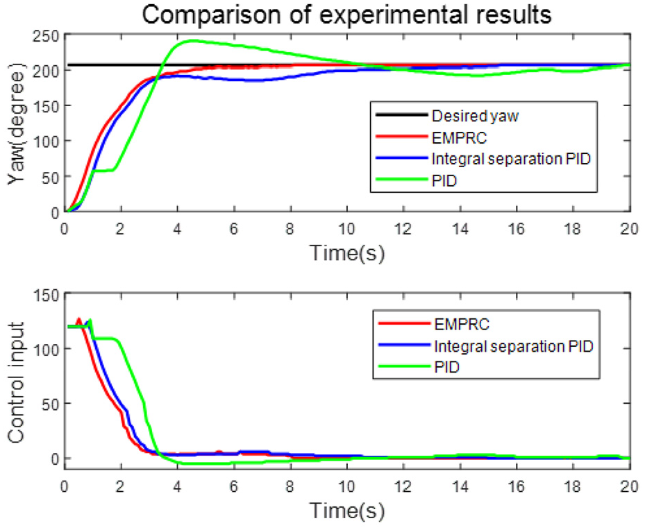
Comparison of yaw (200º) tracking experiments with large deviation.
Finally, a disturbance experiment was performed to verify the anti-disturbance on the performance of controllers. The arbitrary disturbance was generated through an idle propeller in the ROV, which can provide a pulsed disturbance signal of the same intensity to evaluate each algorithm in a fair way. Experimental comparisons are shown in Figure 11. The results show that performance of the three controllers varies greatly under the same intensity disturbance conditions. Both the integral separation PID and the PID have an overshoot of more than
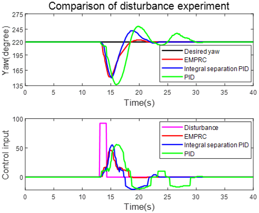
Comparison of yaw (220º) tracking experiments witn strong interference.
Conclusions and future works
The rapid yaw tracking and anti-disturbance capability of the proposed EMPRC algorithm have been both theoretically and experimentally verified against the undesired nonlinear terms and communication delay. The proposed EMPRC method is optimized for hardware configuration and eliminates the residual errors. The experimental evaluation proves the effectiveness of this architecture. In terms of limitations, the authors admit that this method requires more parameter tuning procedures and suggest a system identification to conduct a nominal model for it. This solution can be generalized to varieties of ROVs to impact the practical applications.
The suggested future work would be to expand this method to pitch and roll anti-disturbance control systems by considering the mode coupling between the Euler angles. Control allocation is also worth exploring for this multi-propeller structure to follow complex attitude commands.
Footnotes
Declaration of Conflicting Interests
The author(s) declared no potential conflicts of interest with respect to the research, authorship, and/or publication of this article.
Funding
The author(s) disclosed receipt of the following financial support for the research, authorship, and/or publication of this article: This research was funded by Fundamental Research Funds for the Central Universities under Grant 201962012.