
Abstract
This research investigation has been carried out in Computer Numerical Control (CNC) turning of 40–50 Hardness Rockwell C (HRC) hardened high chromium high carbon steel (HCHCR-D3) specimen for the findings of surface roughness (Ra) and the tool wear. The HCHCR-D3 steel, which has excellent abrasion and wear resistance, is machined with the physical vapor deposition (PVD) coated carbide (CNMG) turning insert nomenclature based on shape, clearance angle, tolerance and type of tool inserts. The coatings preferred are Titanium Nitrate (TiN), Aluminium Chromium Nitrate (AlCrN) and Latuma for the coating thickness of 3–4μm. The varying input parameters of speed and depth of cut under constant feed rate are used as machining parameters for this CNC turning operation. The machined surface characterization and tool wear have been investigated analytically in this manuscript along with the predicted results of effective stresses and temperatures under dynamic cutting conditions in Deform 3D can be related. The outcomes indicate that the depth of cut and the hardening effect (HRC) are the major influencing parameter on surface roughness. Less tool wear and machining time are obtained by the usage of coated CNMG tool insert for high-speed cutting conditions which results in minimization of wear interruption and growth in surface improvements.
Introduction
In the present day, most of the problems have been raised due to wear on lathe tool inserts owing to high-speed machining, more interaction temperatures and poor specimen structure with intricate compositions. The less hardened tool or specimen makes the machining quality as poor. To overcome these issues around the manufacturing sectors, tool coatings have been introduced among the machine shop applications and the hardening effect can be analyzed over the specimen structure and its roughness. Challengeable coatings are used in the present scenario for the various applications due to high-speed machining. To achieve the good surface quality by the involvement of attractive coatings on tool inserts also has to be incorporated in this research work. The wear resistance can be increased due to these bonded PVC coatings. The deposition will improve the material removal with the least amount of tool wear. The main aim of this research is to improve the surface perfections and the tool life by the challengeable machining conditions and coated tools. The complete experimental setup and cutting conditions can be defined based on the better outcomes of the research work that has been carried out by previous researchers. They proved their experiments with some valid data, which would be used for the future implementations in the form of machining constraints or design variables, and so forth. Possibly, we can adopt their reference as our supporting scripts to improve the outcomes of our experimentation. By predicting the performance of the machining and the tool condition by using the dynamic metal forming software tool which can be accomplished by those predicted outcomes used for the error free product development. Agarwal and Khare (2017) has observed that the parameters speed and depth of cut are influencing more on surface roughness in 4140 steel cryogenic turning with less percentage of error during the confirmation experiment. The influence of contact conditions of sliding velocity on the tribological behavior of uncoated tungsten carbide tool against Cu worn material has been observed that the new coefficient of friction was proposed for carbide or Cu contact used to make improvements in the chip compression ratio (CCR) and residual stress (Denguir et al., 2017). The influence of surface roughness on turned cylinders can be identified through the surface topography with CT scans of FDM process. Thus, the least square fitting was found to be smaller than the reference measurements, in which it has been observed that CT dimensional measurements on rough parts are also influenced by the factors (Carmignato et al., 2017). Zou et al. (2019) have been discussed about the identification of surface imperfections using 3D surface micromorphology on the Ultrasonic thread turning of GH4169 superalloy. Very attractive, informative and easy determination of 3D surface roughness by using the height distribution histogram diagram has been also discussed.
Park et al. (2017) experimentally showed that the DHLAM technique is effective in improving machinability by reducing forces and improving surface quality in both Aluminium turning and BMG cutting experiments by laser assisted machining. The surface roughness and MRR were determined and analyzed that the effect of coating thickness with carbide tool in hard turning of AISI D3 cold work steel by the influencing parameters (Singh et al., 2017). Here, the feed rate and coating thickness play an important role in Ra and Feed and cutting speed has contributed more to MRR. The feed rate is the major influencing parameter on surface roughness Ra during the machining of AISI 4140 steel has been identified (Das et al., 2017) that the spot temperature measurement and SEM observations were used to determine and compare the surface roughness measurements. Rao et al. (2018) argued about the optimized cutting parameters in CNC turning of stainless steel 304 by using PVD Nano coated TiAlN carbide cutting tool to differentiate the surface roughness of coated and uncoated carbide tips. It has been found that dry turning of AISI 52100 steel using the TiCN-TiN coated tool influencing more by the feed rate on surface roughness. Keblouti et al. (2017) described that the improvement of surface roughness was caused by decreasing the cutting forces at higher speed, cutting force influenced by the feed rate; the mean value of Ra was considered for the better comparison of coated and uncoated inserts. Noordin et al. (2017) mentioned that the cutting speed is proportional to power consumption and was inversely proportional to the tool life when machined by the coated carbide tool without using cutting fluid. Tool vibration has been measured online by the uniaxial piezoelectric accelerometer in CNC turning of Aluminium alloy 63400, here the results of surface roughness compared with the experimental values by using stylus type profilometer-Talysurf has discussed by Sahooa et al. (2017). Zhang et al. (2018) found that the tool life and surface integrity of high speed turning of Inconel 718 by using TiAlN coated carbide tools. The wear properties were also inspected by SEM images and flank wear has obtained by an optical microscope correspondingly. Optimized machining parameters of CNC turning of EN45 steel by plain carbide cutting tool has been discussed by Kumar et al. (2017). They have analyzed that the feed rate is the most dominant factor in Surface roughness (Ra) and the cutting speed on the metal removal rate and tool wear. Dinesh et al. (2016) have discussed that the two types of tungsten carbide cutter mentioned as straight tungsten carbides and alloyed tungsten carbides. It has finely powdered tungsten carbide with the range of 85–95% with the addition of cobalt ranges from 5–15% that perform as a bonding medium. Additions of different alloying element with the carbide tools also have been discussed.
Performance of PVD mono layered AlCrN and multi-layered AlTiN coated tools were compared in turning of hardened AISI 52100 steel was obtained by Kumar and Patel (2018) and were confirmed that the AlCrN coating exhibited superior anti-oxidation with abrasive particulate when compared with the AlTiN coatings. The effect of machining parameters on cutting forces and surface roughness in turning of Inconel alloy 750 with coated carbide tool was investigated (Dyi-Cheng Chen et al., 2016; Tazehkandi et al., 2015) The metal cutting and the removal of chips can be simulated using Deform 3D and also to identify the deflection and stresses for the different actuation available during the deformation. They have discussed about the effective stress influence on chip removal and the consistent flow of turning tool temperature in the cutting tips which has been related with the tool wear. Dyi-Cheng Chen et al. (2019) have discussed the importance of DEFORM, which can be used to predict and analyze the stress, strain, velocity, temperature, displacement and different simulation outcomes in metal forming and they mentioned that this could improve the design and process defects and the reduction of cost and time in the manufacturing sectors. Also, they determined the effective stress results of simulated battery outer casing model, which concludes that better formability was done on the Al6061 square specimen having double-sided and the single-sided lubrication with the thinnest thickness.
Here, the feed rate and cutting speed are the most effective parameters on surface roughness and depth of cut on cutting forces simultaneously. An increase in the depth of cut severely increases the cutting forces. Padhiyar and Nair (2017) discussed the combined effect of process parameters on surface roughness machined with two TNMG, DNMG cutting tool inserts. Here, the lowest surface roughness was achieved 0.648μm by using the TNMG tool when compared with the DNMG tool. Here, in this experiment, the hardened effect on steel specimen is turned by using PVD coated CNMG cutting tool inserts, which will get better surface roughness compared with the existing values with the additional benefit of less tool wear has been attained. The machining time also has been saved by the influents and attractive coatings were applied on tool inserts.
Experimental procedure
Materials and methods
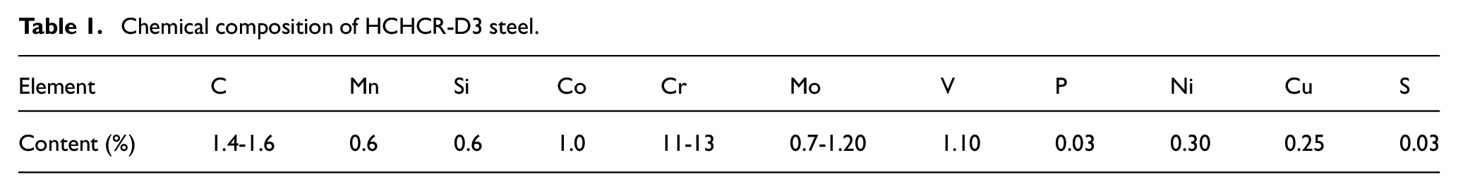
In order to examine the effects of the planned experimental process were performed on High chromium high carbon steel HCHCR-D3 is an air-hardening tool steel that has high wear, abrasion resistance and heat treatable and will offer a hardness around 55-62 HRC. The composition of HCHCR-D3 steel is mentioned in the following Table 1. It is machinable in the annealed condition and shows little distortion on correct hardening. It is also has a density of 7700 kg/m3 up to the melting point of 1421°C. The tools used here are CNMG-431-MA (CNMG120404) carbide inserts and MCGNR-M12 holder for the Insert Size of 12x5mm/0.472x0.196”, as shown in Figure 1. MCGNR-M12 CNMG Tool holders are high precise rigidly clamped element, which have good hardness as well as toughness. It will produce faultless machining effect. It is applicable for turning and facing with suitable cutting fluid. This will improve the cutting efficiency and can reduce tool grinding cost that ensure the glossy surface of the cutting profiles. The entire turning operations were performed in the CNC turning center Hwacheon ECO-2SC2, as shown in Figure 2. It is a turret headed design with Fanuc controlled 3-Jaw hydraulic chuck and tailstock. The powerful torque can be produced with the turbo chip conveyor. The automatic coolant system and lubrication system can be adopted with its setup. The parameters of speed and depth of cut were selected based on the suitable HRC grade from ISO standard data book for the cutting of hardened specimens. The constant feed rate was maintained for the easy and better comparison of surface roughness. The specimens were hardened at different levels of hardening up to 40, 45 and 50 HRC. Evaluation tests of the conventional turning of HCHCR-D3 steel were performed with different speeds and depths of cuts. Proper lubricants were applied for all the tryouts and the feed rate (f) was maintained constant at 0.2 mm/rev, respectively. The length of the turning for each cut was approximately 40 mm. Instead of using uncoated carbide inserts, the three different coated CNMG inserts are used.
Chemical composition of HCHCR-D3 steel.
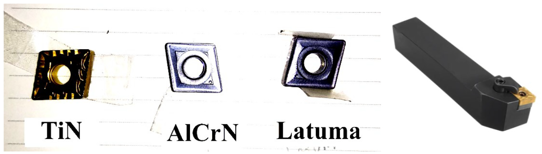
Coated CNMG carbide inserts and MCGNR holder for CNC turning.
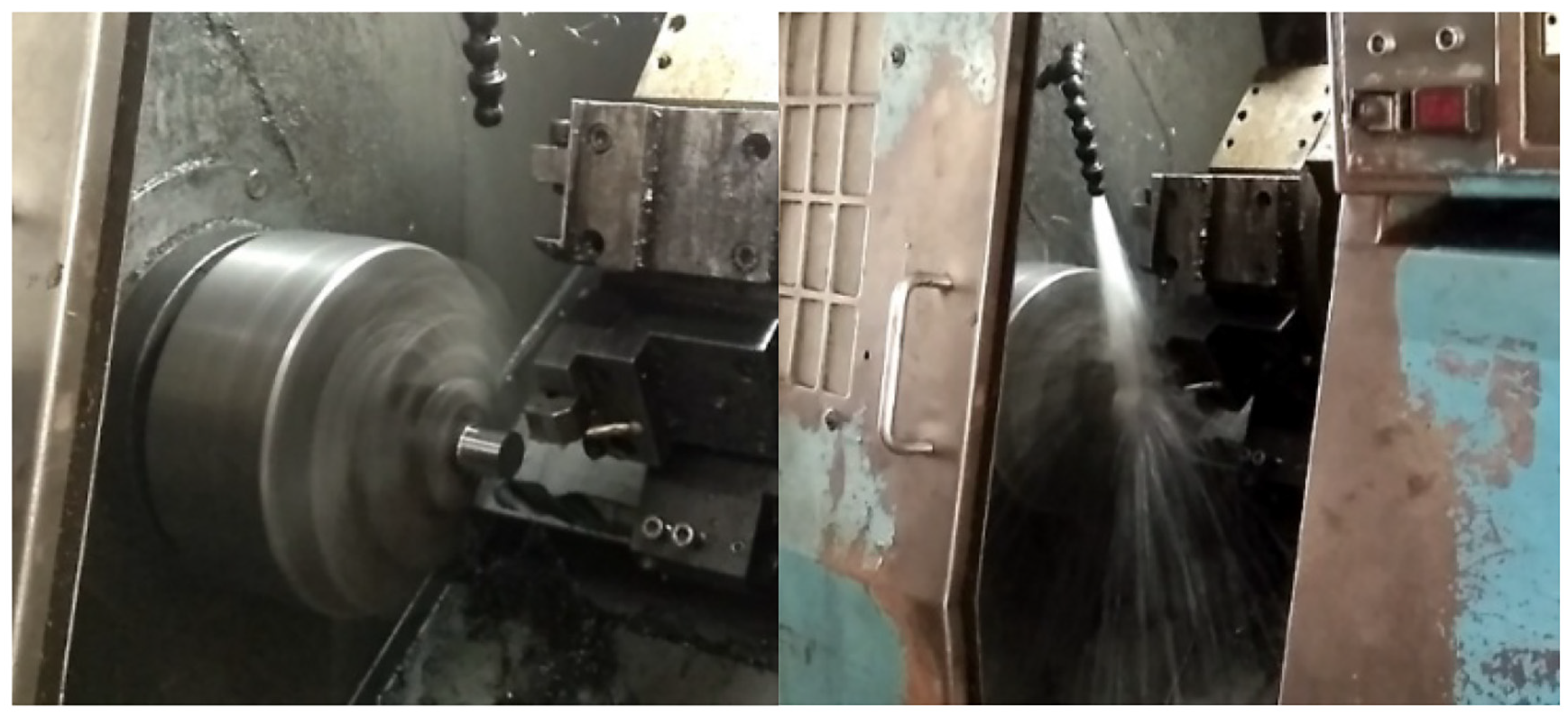
CNC turning center Hwacheon ECO-2SC2.
Coatings and dynamic simulations
The coatings are preferred Titanium Nitrate (TiN), Latuma and Aluminium Chromium Nitrate (AlCrN), as shown in Figure 1. The tools were coated with the TiN, AlCrN and Latuma deposition by PVD method as mentioned in machining conditions of Table 1. Most of the coatings were executed in Oerlikon Balzers Ltd., after completion of turning process; the surface roughness is measured by using highly precise Mitutoyo SJ-201surface roughness tester, as shown in Figure 3. The dynamic simulation tool is used here for the prediction of stresses and temperatures acting along with the tool work interface in the cutting zone of the turning process by using Deform 3D. The fine mesh generation was accomplished over the specimen and the tool inserts by the relative mesh size of 25000 for the specimen and 15000 for tool insert. The materials properties were selected from the material library of Deform 3D. The tool inserts CNMG solid mesh was generated with 25968 elements and 6039 nodes following this the workpiece HCHCR-D3 steel solid mesh was generated by 13,708 elements and 3232 nodes, as shown in Figure 4. The machining conditions were entered in the prescribed area as mentioned in Table 2. The boundary conditions were applied for the workpiece fixed on two axes and rotation about its own axis and the tool insert is prevented in both the axis.
Measurement of surface roughness on hardened HCHCR-D3 steel turned specimen.
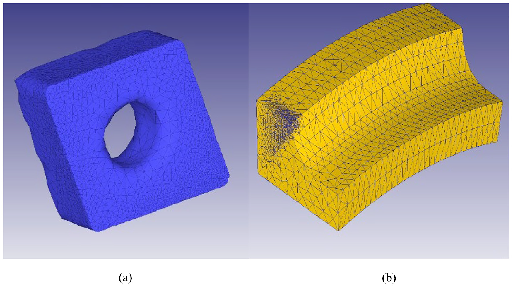
Deform 3D Mesh generation of (a) CNMG tool insert, (b) HCHCR-D3 steel specimen.
Results and discussion
Based on machining conditions speed, feed, and depth of cut were selected on suitability machining conditions for the coated carbide tip. The experimental readings have shown in Table 3. The Rockwell hardness (HRC) value is the most influencing parameter on surface roughness has been identified for the 150 kg load condition. The more hardened cylindrical specimen with 50 HRC value having excellent strength to deliver good surface finish. We received less surface roughness values of 0.338μm and 0.799μm, obtained during the turning of more hardened (50 HRC) specimens. If the HRC value increases, the surface roughness becomes decreased. Meanwhile, the depth of cut increases for each experiment. Coated carbide tips were used in this turning operation for developing the quality of the surface and machining time was reduced by the increase of rotational speed from 900 rpm to 1200 rpm. Constant feed rate helps to elevate the range of roughness increments. Machining was reduced by the usage of the AlCrN coated turning tool at high rotational speeds by the smooth travel of cutting tool without interruptions. Less surface roughness 0.338μm was obtained by the usage of the TiN coated carbide tip for the 50 HRC hardened specimen.
Experimental observation of surface roughness (Ra), machining time (t) and wear levels for the constant feed rate of 0.2 mm/rev.
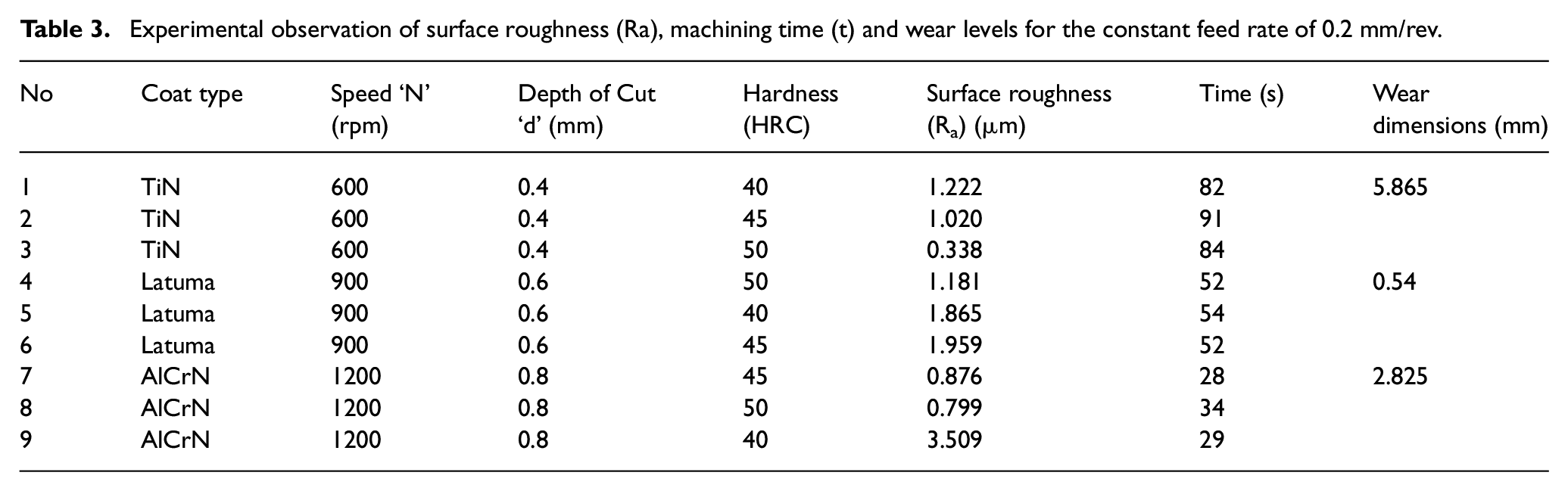
Comparison has been made with some existing research, in which evidence that the surface roughness evaluated in the range of 0.8μm to 1.03μm on turned D3 cold work steel (Singh et al., 2017) and 0.785μm roughness were obtained by TNMG and 1.525μm by DNMG tooltips attained for the turning operation of Die steel, respectively. By comparing these enumerations, our research project outcomes are relatively better in surface roughness parameters as 0.338μm and 0.799μm at lower depth of cut and constant feed rates, as mentioned in Table 3. Similarly, Kumar et al. (2017) and Das et al. (2017) also explained in their evaluations that the usage of EN45 and 4140 steel with 52 HRC hardened specimen achieved the roughness minimum of 0.825μm to 1.818μm as maximum. But in our research work, based on the hardening effect of 40 -50 HRC, the surface integrity was achieved with the fewer values of 0.338μm and up to 1.959μm which has been mentioned in Table 3.
Forecast of stress and temperature
The effective stress is nothing but Von Mises stress, which is exactly suitable for ductile materials like steel and aluminium. Here, for the rotational speed of 600 rpm, the minimum effective stress of 1190 Mpa was obtained at the nodal point of 2992 on the turned area with the minimum interaction temperature value of 161°C was recorded during the simulation steps of Deform 3D. The rotational torque of 3.43 x 10³ N-mm with respect to the time signature of 0.000198 seconds can be received by the Deform 3D simulation results as mentioned in Figures 5(a) and (b). The depth of cut is maintained as 0.4 mm. Similarly, for the rotational speed of 900 rpm, the effective stress was recorded relatively maximum as 1320 Mpa is acting in the 50th simulation step for the rotational torque of 5.29 x 10³ N-mm with respect to the time signature of 0.000139 seconds. The temperature can be predicted here as 408°C in that particular point of tool work interaction for the depth of cut 0.6 mm. The moderate value of effective stress 1210 Mpa and the interaction temperature of 243°C initiated at the step of 50 out of 100 simulation steps during the high rotational speed of 1200 rpm with the rotational torque of 7.15 x 10³ N-mm with respect to the time signal of 0.000111 seconds, as mentioned in Figures 5(a) and (b).
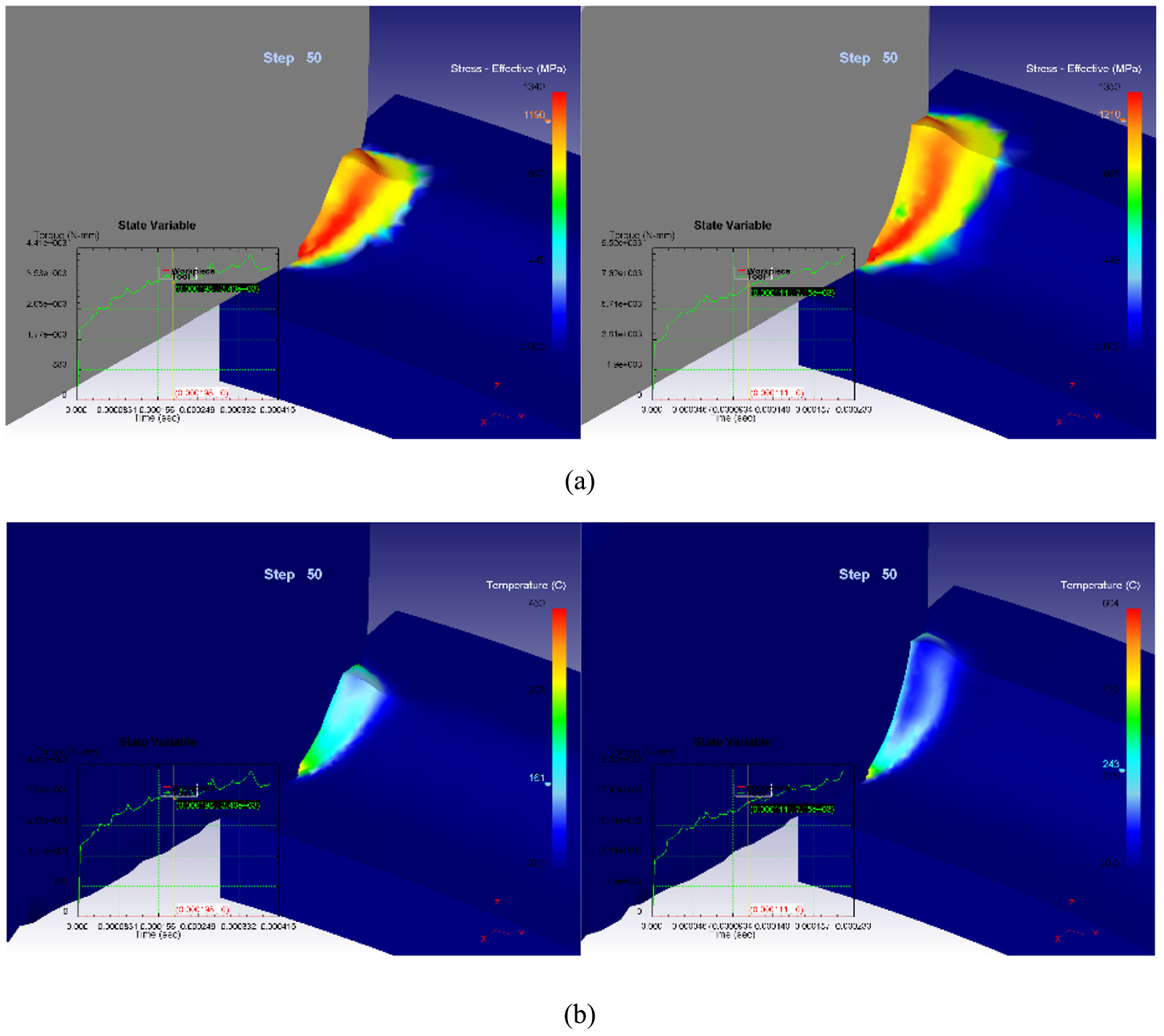
Simulation results of (a) effective stresses (b) tool-work interaction temperature for the rotational speeds of 600 rpm, 900 rpm and 1200 rpm at various depth of cuts, f=0.2 mm/rev (constant).
The effective stress increases in the predicted level of simulation steps if the rotational speed and depth of cut increases. For the 0.6 mm depth of cut, very little change has occurred in the stress effective at the medium rotational speeds. If the effective stress is minimum in the predicted level, the good surface finish was obtained and the rotational speed is acting as a dominant parameter on machining time and effective stress changes. Similarly, if the temperature of tool-work interaction decreases, the less surface roughness of 0.333μm was obtained. In some cases, due to a high depth of cut with the addition of high rotational speed and the HRC grade, the perfect surface integrity has got. Hence, it has been proved that the depth of cut is the major dominant parameter on surface roughness.
Effect of coating on tool wear and surface integrity
By the completion of the turning process, the values of surface roughness were measured over the turned specimen by the roughness tester Mitutoyo. The smaller amount of surface roughness values was obtained by the use of AlCrN and TiN coated carbide tips as 0.339μm and 0.799μm, respectively.
After completing the surface roughness measurement, the tool wear has been analyzed by using the METCO tool maker’s microscope, which had magnification 30X up to 100X levels with a linear accuracy of 200μm by viewing the clear fringe images through the eyepiece captured by the camera center, as shown in Figure 6. The wear span of the carbide inserts tips clearly viewed through the eyepiece markings and measure the lengths of each corner wear by the micrometer (50 mm, L.C 0.01) scale attached at the end of both horizontal axes. Setting up the origin as zero and measure the wear edge length by adjusting the anvils.
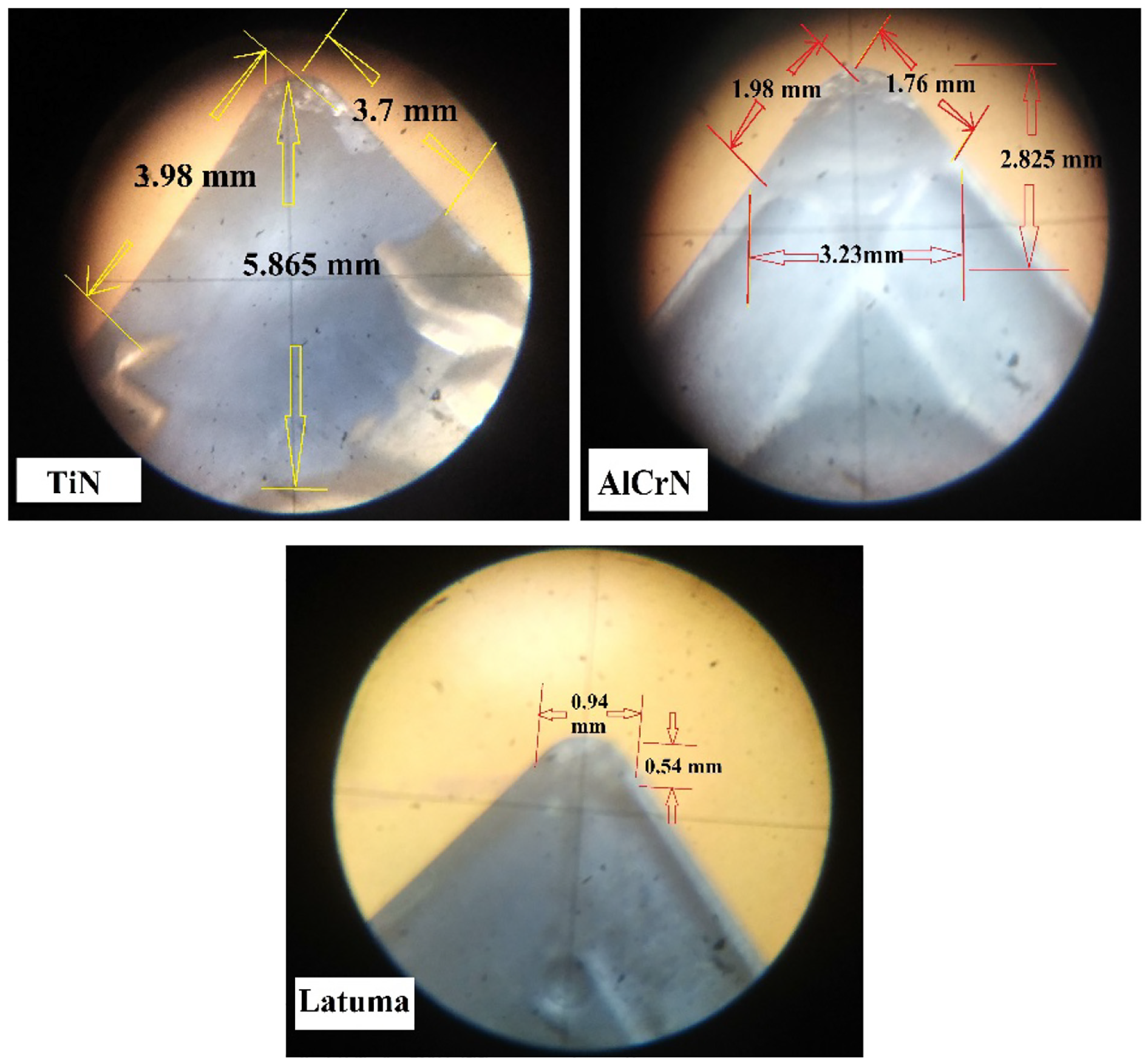
Tool wear measurement on coated (TiN, AlCrN, Latuma) turning carbide inserts by toolmakers’ microscope.
The coincidence of thimble and main scale readings easily identifies the values of tool wear lengths. The largest wear has occurred in the TiN coated carbide tips and less tool wear was in Latuma coated carbide tips, as shown in Figure 6. The moderate values of tool wear have been identified in the AlCrN inserts. The largest tool wear of 5.865 mm in the top face of the TiN coated tooltip was recognized and the less tool wear of span 0.54 mm was acknowledged in the cutting edge of Latuma coated carbide tip.
Moreover, the better tool life was obtained using the Latuma coated CNMG tool insert based on its less wear area recorded in the tool maker’s microscope outcomes and also the surface roughness achieved on the steel specimen is well and good during the usage of AlCrN coated tool inserts. The marvelous reason behind this is nothing but the hardened specimen nearby 45–50 HRC relatively harder than the normal steel grades or either hardened or not; so that the tool could be worn out easily at high depth of cut and rotational speeds. Nevertheless, due to the well-bonded PVD coatings, Latuma and AlCrN both performed well in the reduction of tool wear and the improvement of surface quality. The additions of Titanium and Aluminum contents in rich coatings are the important reason for these surface improvements and wear resistance. The PVD coated inserts that contain more amounts of Ti particles and less of Al, Cr particles were deposited over the machined surface of D3 steel and it was bonded with the assistance of interaction temperatures of tool and work surface during machining. This clearly shows the particulate attraction in the SEM images of the turned surface of hardened steel specimen, as shown in Figure 7. The deposited particle sizes were identified clearly with the size range of 0.40μm to 0.76μm over the turned surface of D3 steel, which is machined with the AlCrN coated CNMG tool inserts. In addition, the participation of 11–13% Chromium alloying elements in HCHCR-D3 steel, mentioned in Table 1 are used to improve the machinability and resistance to corrosion. This was benefited in addition to the enhancement of surface roughness values, as shown in Table 3. So, reasonable improvements were stabilized in both surface quality and tool life and were preserved better in this investigation.
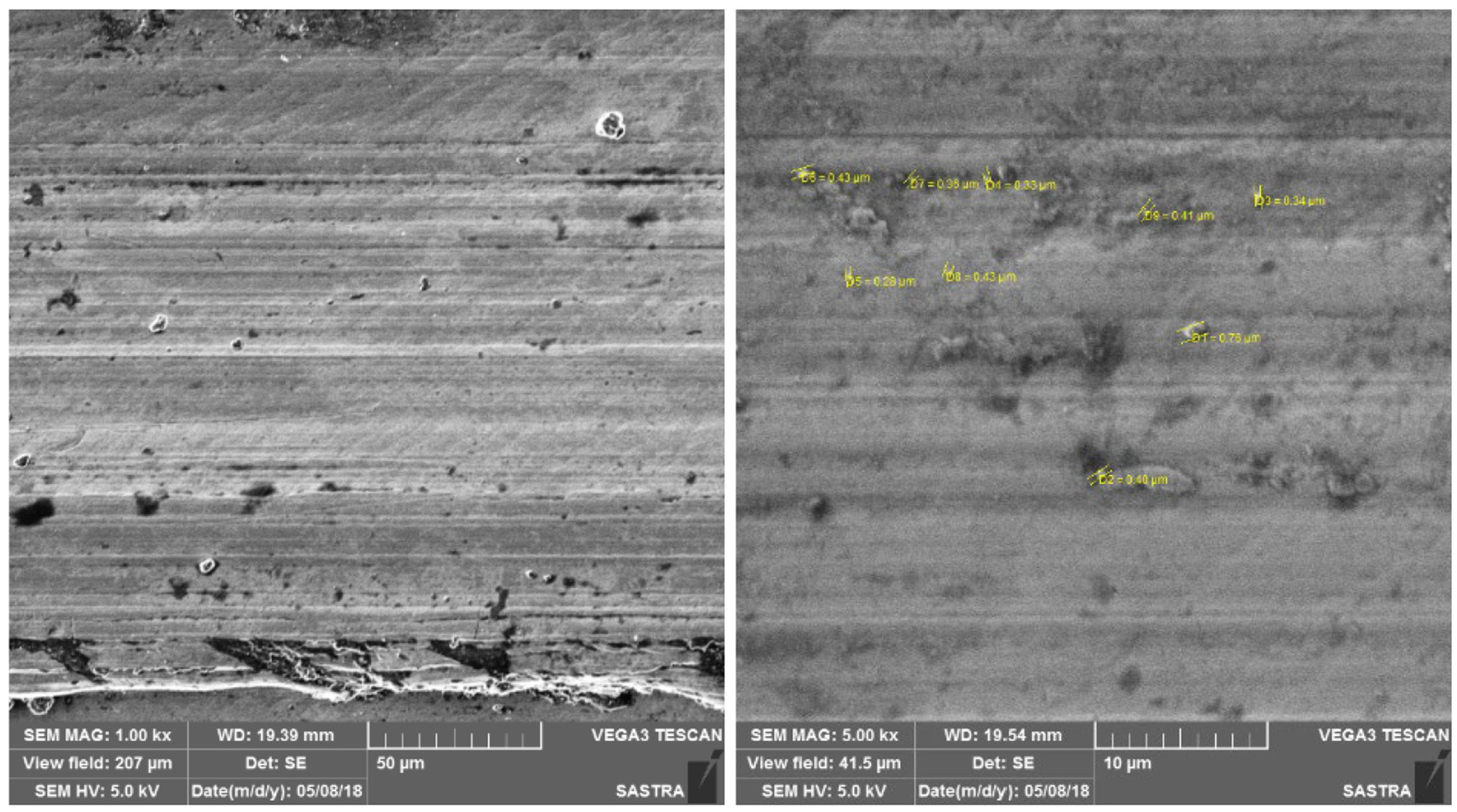
SEM images of the turned surface of the HCHCR-D3 hardened steel from the magnification of 500x, 1.0 kx and 5.0 kx (Particle size range 0.28μm~0.76μm).
Conclusion
In this tract of research, there are three different coatings that were applied on CNMG cutting tool inserts by the PVD method. The roughness levels of the turned specimen were classified based on the coatings involved and the hardening effect HRC of the D3 steel specimen. The depth of cut is the most dominant parameter on surface roughness; in addition, the coatings are also a good initiator of improving the surface quality. In addition, the inclusion of Cr alloying elements and the hardened effect of 50 HRC, the good surface finish was obtained on the specimen. The tool wear identification becomes a very clear impression by the involvement of TiN, AlCrN and Latuma coated inserts. Less tool wear and improved tool life were obtained well by the Latuma coated tool based on the dimensions of tooling microscopic fringes. Better surface roughness was recorded by the machining with AlCrN and TiN coated tool inserts. But there are no reasonable highlights in Ra that were obtained by Latuma. It may be better by utilizing alternative machining conditions as future scope. Prediction of stresses and temperatures of the cutting zone by Deform 3D tool certainly supports to recognize the improvement of tentative records. The particle deposition is the main route cause of realizing the roughness and is finely visualized by the SEM images with optimum magnification levels. The highest requirement has been met with TiN and AlCrN coated CNMG tools which has been used to get minimum surface roughness compared with some existing research reviews. Thus, the correlation of surface roughness, particulate dispersion and the pot processed simulation results has been obtained. Furthermore, the surface, tool life improvement will be elevated with the newly coated tools and the thermal changes by the tool-specimen interaction temperature effects will be identified with some alternative machining conditions as future scope.
Footnotes
Appendix
Declaration of conflicting interests
The author(s) declared no potential conflicts of interest with respect to the research, authorship, and/or publication of this article.
Funding
The author(s) received no financial support for the research, authorship, and/or publication of this article.