
Abstract
To enhance the tribological properties of titanium alloy surfaces, this study employed a combination of laser nitriding and texture weaving to construct nitrided surfaces with periodic textures on Ti6Al4V substrates. The prepared nitrided surfaces exhibited superior wear resistance, and the effects of various laser process parameters on wear resistance were systematically investigated. Detailed analyses of microhardness, phase composition, and elemental distribution were conducted to elucidate the wear mechanisms. At a laser power of 12 W and a scanning speed of 15 mm/s, the nitrided surface achieved a hardness of approximately 1300 HV0.2, with wear scar dimensions of 3.35 µm in depth, 475 µm in width, and a wear mass loss of 106 mg. Additionally, the influence of laser parameters on the contrast and print growth of nitrided Data Matrix code modules was evaluated to assess their readability. The results demonstrate that laser gas nitriding with texture weaving significantly improves the wear resistance of titanium alloy surfaces and the durability of Data Matrix codes, offering new possibilities for designing multifunctional surfaces and high-performance marking applications.
Introduction
With the advancement of information technology, increasing demands have been placed on traceability in the manufacturing industry. A fundamental prerequisite for achieving traceability of components is ensuring each part possesses a unique identifier. Laser marking technology enables the creation of permanent, high-resolution Data Matrix (DM) codes (A high-density 2D barcode composed of square or rectangular cell structures, designed for rapid access to critical data) on the surfaces of various materials, including metals, glass, and ceramics. These codes facilitate comprehensive traceability of product development, production, sales, and quality data, thereby supporting full life-cycle management throughout the manufacturing process.1–4However, DM codes laser-marked on titanium alloy surfaces are susceptible to degradation under complex service conditions, including oxidation and wear in atmospheric environments. Such deterioration compromises the integrity and legibility of the DM codes, resulting in data loss and diminished quality assurance. This, in turn, severely impacts the traceability and reliability of titanium alloy components throughout the manufacturing process. Consequently, enhancing the surface hardness and wear resistance of laser-marked titanium alloys has become a critical focus in both research and practical applications related to surface engineering and traceable manufacturing.5–8
The poor tribological properties of titanium alloy surfaces are a significant drawback. Currently, traditional surface modification techniques include thermal spraying, electrochemical machining, and ion etching.9–11 Among these, thermal spraying results in a coating that primarily bonds mechanically to the substrate, making it prone to peeling under impact or high loads. Additionally, the hardness and bonding strength of parts can be unevenly affected by factors such as varying penetration depths and dilution rates. Furthermore, the surface hardness and wear resistance of parts are not significantly improved due to factors like the dilution rate of the welding wire and the base material. Electrochemical processing methods may cause hydrogen atoms to penetrate the metal during electroplating, potentially leading to brittle fracture, and may result in edge effects (excessively thick coatings at corners), causing uneven coating distribution; ion etching and other methods have lower etching rates compared to mechanical processing, making them unsuitable for large-scale or rapid production, and difficulty in precision control may lead to surface unevenness or excessive etching, causing damage to the substrate. In contrast, laser surface modification has emerged as a promising alternative to overcome these limitations. Unlike traditional techniques, laser surface modification enables precise synthesis of high-performance cladding layers tailored to specific surface performance requirements. Notably, laser gas nitriding allows for the rapid formation of a metallurgically bonded nitride layer on the titanium alloy substrate, significantly enhancing surface hardness and wear resistance.12–14Pulsed lasers have become an indispensable tool in modern precision manufacturing and medical applications due to their efficient interaction with materials, ability to generate extremely high instantaneous power, and technical flexibility. 15
C.H. Ng et al. 16 employed laser-induced growth technology to fabricate a titanium nitride (TiN) grid on the surface of nickel-titanium alloy (NiTi). Through reciprocating wear tests against ultra-high molecular weight polyethylene (UHMWPE), the wear resistance of the nitrided samples was evaluated. However, the underlying wear mechanisms of the nitrided layer remain unexplored.Xiao Zong et al. 17 conducted laser nitriding on titanium alloy TC11, providing a detailed discussion on the formation process of TiN phases from the perspective of lattice transformation. Linear reciprocating ball-on-flat wear tests were performed to assess wear resistance, yet the evaluation methodology and mechanistic interpretation of wear behavior require further elaboration.Research on the influence of laser process parameters on material performance and reading quality has demonstrated that scanning speed, peak power, frequency, and heat input significantly affect the corrosion resistance and surface roughness evolution of 316 stainless steel. The analysis reveals that laser beam scanning speed is the dominant factor governing scanning accuracy. 18 In laser marking studies on carbon structural steel 15Cr2, the relationship between laser power density, frequency, and marking contrast under varying marking speeds was elucidated. 19 Li Xiashuang et al. 20 systematically examined the correlation between laser parameters and the readability, marking time, and contrast of DM codes directly laser-marked on aluminum alloy surfaces, with a focus on the impact of laser parameters on DM code contrast.To date, most research has focused on the effects of laser parameters on nitrided surface characteristics. However, investigations into the wear mechanisms of nitrided layers remain limited, and studies on DM code laser marking have predominantly centered on aluminum alloy surfaces. Therefore, developing a DM code marking process for titanium alloys that simultaneously ensures high wear resistance and excellent readability is of urgent importance.
In summary, this study investigates the effects of laser process parameters on the surface characteristics of titanium alloys subjected to laser gas nitriding, with a particular focus on enhancing the tribological performance of the nitrided layer and elucidating its underlying wear mechanisms. Furthermore, the study integrates the laser gas nitriding process with DM codes marking on titanium alloy surfaces, analyzing the effects of module contrast and mark growth on the readability and quality of the encoded information. The findings provide a theoretical foundation for improving both the wear resistance and the readability of laser-marked DM codes on titanium alloys under complex service conditions.
Materials and testing
In this study, titanium alloy samples with a diameter of 25 mm and a thickness of 4 mm, supplied by Baoji Baoti Group Co., Ltd (China), were used. The specific elemental composition of the titanium alloy is listed in Table 1. Prior to the laser nitriding experiments, the substrate surfaces were sequentially polished using 400CW, 600CW, 800CW, 1000CW, and 1500CW grit silicon carbide sandpapers on a HEJAMP-2 metallographic grinding and polishing machine. Subsequently, the samples were ultrasonically cleaned in ethanol using a KM-615B ultrasonic cleaner for 15 min and then allowed to air-dry naturally.
Chemical component of Ti6Al4V.
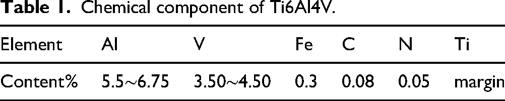
Figure 1 illustrates the laser irradiation system and the schematic diagram of the laser processing path used in this study. A nanosecond laser marker (HGTECH-LSF20D, Wuhan Huagong Laser Engineering Co., Ltd, China) was employed, with a laser pulse duration of 200 ns, a wavelength of 1064 nm, and a spot diameter of 50 μm. The substrate was placed in a sealed nitrogen gas chamber with a nitrogen purity of 99.99%, covered by a high-transparency quartz glass window. This setup ensured the maintenance of a laminar nitrogen flow and stable pressure conditions, thereby preserving the purity of the protective atmosphere during laser processing.The laser beam was directed through the quartz window onto the surface of the titanium alloy substrate to produce an 8 × 8 mm² nitrided marking area. The effects of laser power and scanning speed on the wear resistance of nitrided surface were systematically studied. The corresponding experimental marking parameters are summarized in Table 2.Tribological performance was evaluated using a reciprocating friction and wear tester (Lanzhou Zhongke Kaihua Technology Development Co., Ltd, China). A Si3N4 ceramic ball was used as the counterface material, under a normal load of 2 N, a sliding speed of 240 mm/s, and a total sliding time of 30 min.
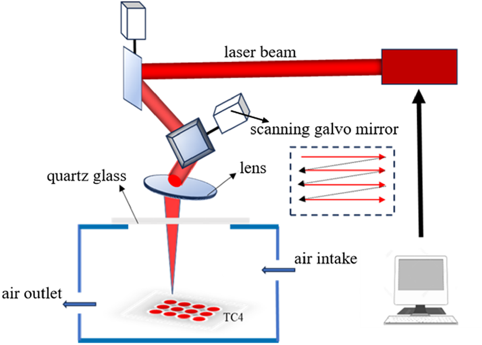
Laser nitriding system and laser scanning path.
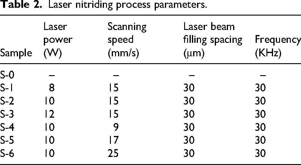
Laser nitriding process parameters.
The width, depth, and two-dimensional profiles of the wear tracks were analyzed using a confocal microscope (Smartproof 5, ZEISS, Germany). The micro-morphology of the worn surfaces was further examined using a scanning electron microscope (SEM; TESCAN CLARA, Czech Republic). Elemental distribution on the laser-nitrided surfaces was characterized via energy-dispersive spectroscopy (EDS; UltimMax TLE, Oxford Instruments, UK). Phase composition on the nitrided regions was identified using an X-ray diffractometer (D8 Discover, Bruker, Germany).The surface microhardness of the nitrided layers was measured with a Vickers microhardness tester (Wuhan Shangcai Technology Co., Ltd, China), and the reported value represents the average of six measurements per sample. Additionally, a DM code was marked on the sample surface using the same laser processing parameters, and its quality was evaluated using a DM code quality verifier (UID-DPM 002, Microscan, USA).
Results and discussion
Laser nitriding surface morphology analysis
Figure 2(a) displays the surface morphology of the untreated Ti6Al4V sample (S-0) and the samples subjected to laser gas nitriding (S-1 to S-6). After nitriding, the original metallic luster of the titanium alloy surface is replaced by a golden-yellow layer, attributed to the formation of titanium nitride. The surface color of the nitrided samples varies depending on the specific laser processing parameters. For instance, with increasing laser power, the surface color gradually shifts from a light to a darker golden-yellow tone, as observed in samples S-1, S-2, and S-3. At lower scanning speeds, the surface (S-4) exhibits a brownish hue, whereas at higher scanning speeds, the surface (S-5,S-6) regains a golden-yellow appearance, indicating changes in nitrided layer composition and morphology due to thermal input variations.
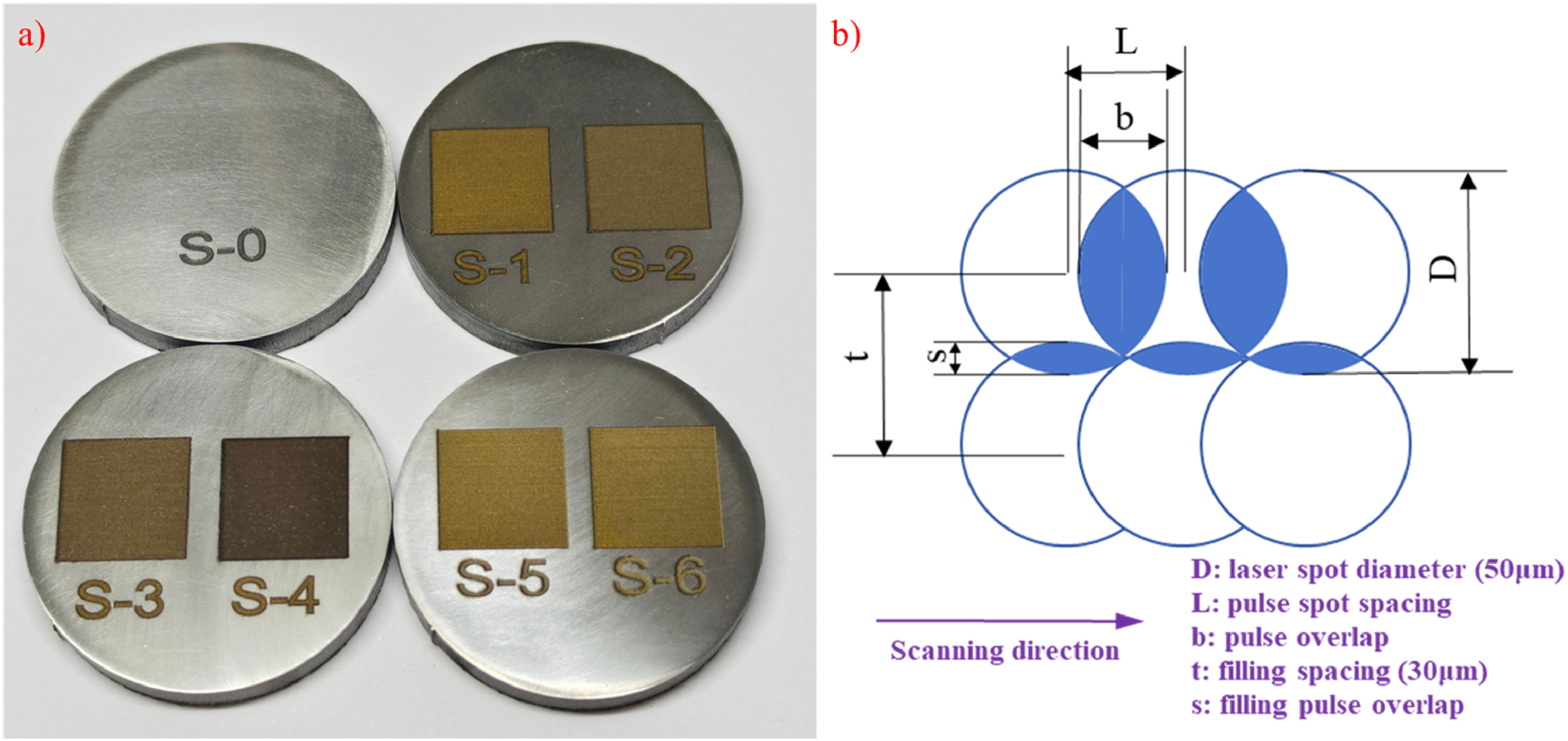
(a) Surface Laser Nitriding sample of Ti6Al4V. (b) Schematic diagram of scanning overlap rate.
Figure 2(b) presents a schematic illustration of laser pulse overlap and scanning overlap. As illustrated in the figure, D represents the Laser spot diameter of 50 μm, and t denotes the filling spacing of 30 μm.The parameter s indicates the filling pulse overlap, which varies with changes in the filling spacing. Meanwhile, L and b represent the laser pulse spot spacing and pulse overlap, respectively, both of which are influenced by the scanning speed.Laser gas nitriding is a highly complex process involving multiple physical and chemical interactions. When the laser beam irradiates the titanium alloy surface, phenomena such as heat conduction, convection, and radiation occur simultaneously. The intense localized heating causes instantaneous melting and evaporation of the substrate, resulting in the formation of ablation pits. By adjusting the scanning speed, the spacing between successive laser pulses—and thus between adjacent ablation pits—can be controlled. A high degree of pulse overlap leads to the formation of periodic groove-like textures due to overlapping ablation pits.Similarly, scanning overlap is influenced by the spacing between successive laser scan lines. In this study, the laser line spacing was fixed at 0.03 mm, thereby keeping the scanning overlap constant throughout the experiments. The degree of pulse overlap was calculated using the equations proposed by Yasa E,
21
as presented in Equations (1) and (2):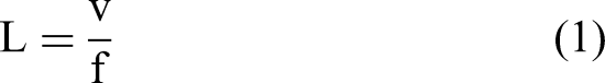
L denotes laser pulse spot interval, v denotes laser scanning speed,
Figure 3 presents the SEM images of laser-scanned regions under different laser powers and scanning speeds, where the periodic textured grooves induced by laser ablation are clearly observed. Figure 3(a) to (c) show that in the power range of 8–12 W, an increase in laser power leads to a corresponding rise in the recoil pressure due to enhanced laser energy absorption. This elevates the surface temperature of the material, inducing the formation of a liquid-phase molten pool through vaporization, melt ejection, and internal convection. Simultaneously, reactive nitrogen atoms diffuse into the substrate, facilitating the nitriding process.Varying laser powers result in different energy densities at the laser–material interaction zone, thereby causing non-uniform energy distribution and affecting nitriding quality. At excessively high laser powers, titanium nitride (TiN) formed on the surface may undergo ionization or vaporization, generating plasma that adversely impacts the integrity and uniformity of the nitrided layer. Figure 3(d) to (f) illustrate the textured grooves generated at different scanning speeds within the range of 9–25 mm/s. As scanning speed increases, the spacing between adjacent laser pulses also increases, leading to larger gaps between successive ablation pits. Higher scanning speeds result in reduced pulse overlap, diminished molten pool formation, and lower surface temperatures, which prolong the time required to reach the melting point of TiN. In contrast, lower scanning speeds yield greater pulse overlap. The energy accumulated in regions with overlapping pulses is the cumulative energy from adjacent laser spots, leading to higher material removal rates and larger melt pools. Consequently, different pulse overlap levels significantly influence the morphology and size of the resulting melt pools.

SEM images of Ti6Al4V nitrided samples with different laser parameters. (a) S-1, (b) S-2, (c) S-3, (d) S-4, (e) S-5, (f) S-6.
During laser nitriding, the rapid heating and cooling cycles induce complex thermal and residual stresses in titanium alloys, significantly affecting the mechanical properties and structural integrity of the nitrided layer. The localized high-energy input generates steep thermal gradients, leading to transient tensile stresses as high as 1.2–1.5 GPa during heating, followed by residual compressive stresses upon cooling due to plastic deformation in the heat-affected zone (HAZ) and martensitic phase transformation. These stress states can promote extensive surface cracking. 22 Studies indicate that residual stresses in laser gas nitriding exhibit a positive correlation with laser power but an inverse relationship with scanning speed. 23 In this study, preliminary experiments were conducted to optimize the process parameters, ultimately selecting a laser power range of 8–12 W and a scanning speed range of 9–25 mm/s for single-pass laser processing. By optimizing the laser parameters to minimize the cracking problem of the nitride layer, it can be seen from Figure 3 that the surface of the prepared sample has no large areas of obvious cracks.
Elemental and phase analysis of nitrided surfaces
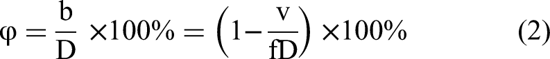
As illustrated in Figure 4(a) and (b), pronounced ablation traces are observed on the surface of the S-3 sample. According to the results of elemental mapping (EDS) and the corresponding surface elemental composition, a significant presence of nitrogen (N) is detected on the nitrided surface. The detailed elemental compositions of the nitrided samples are summarized in Table 3. Compared to the pre-nitriding composition in Table 1, a marked increase in nitrogen content and a concomitant decrease in titanium (Ti) content are observed, indicating successful nitrogen incorporation during the nitriding process.

Analysis of surface elements and physical phases of laser nitrided Ti6Al4V samples.(a,b) EDS element mapping.(c) Cross sectional morphology of laser nitrided samples. (d) EDS elemental composition analysis.
Chemical composition of laser nitrided Ti6Al4V.
To further investigate the depth characteristics of laser nitriding, titanium alloy samples (8 × 8 cm²) were prepared by mechanical cutting and precision polishing. The samples were subjected to full-surface laser nitriding using the same parameters as Sample S-3. The cross-sectional microstructure and elemental distribution were subsequently analyzed using scanning electron microscopy (SEM) and energy-dispersive X-ray spectroscopy (EDS).As shown in Figure 4(c) and (d), laser nitriding resulted in a distinct modified surface layer. Cross-sectional observations revealed three well-defined regions: (i) the outermost laser-nitrided zone (LNZ), (ii) an intermediate heat-affected zone (HAZ), and (iii) the base material (BM). Notably, these regions exhibited excellent metallurgical bonding.EDS line-scan analysis along the depth direction confirmed a gradient distribution of nitrogen, with concentration progressively decreasing from the surface toward the substrate. Furthermore, the nitrided layer thickness was found to be strongly dependent on laser processing parameters. Increasing laser power led to a corresponding increase in layer thickness, whereas higher scanning speeds resulted in a thinner nitrided layer. 24 This trend clearly demonstrates the gradual attenuation of laser nitriding effects with increasing depth.
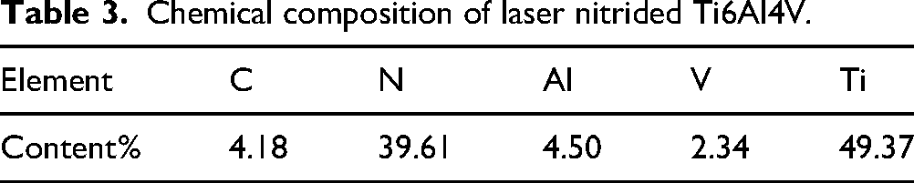
To further investigate the crystalline phases formed on the laser-processed surface, X-ray diffraction (XRD) analysis was performed. Figure 5(a) shows the XRD patterns of both untreated and laser-nitrided samples, clearly revealing the formation of titanium nitride (TiN) phases in the latter. Figure 5(b) presents the intensity of the TiN diffraction peaks under various laser processing parameters. During laser nitriding, nitrogen diffuses into the substrate and reacts with titanium to form TiN. As the laser power increases, the laser energy density rises, elevating the temperature of the nitriding region and extending the duration of the molten state. Consequently, more energy is absorbed by the surface, leading to enhanced TiN formation and a corresponding increase in the TiN diffraction peak intensity and nitrogen content.
(a) XRD results of untreated and laser nitrided surfaces (s-3). (b) XRD results of nitrided surfaces with different laser power.
However, under conditions of high laser power and low scanning speed, the elevated temperatures may also promote partial decomposition of stoichiometric TiN, resulting in the formation of titanium-rich subnitrides (TiNx, where x < 1). These non-stoichiometric nitrides typically exhibit darker coloration, ranging from brown to black, as observed in sample S-4. In contrast, at higher scanning speeds, the laser dwell time is reduced, leading to shallower melt pools and slower nitride solidification. This inhibits the diffusion and dissolution of nitrogen, thereby reducing the TiN content and the intensity of its diffraction peaks in the nitrided region.Additionally, changes in the α-Ti and β-Ti diffraction peaks are observed, which can be attributed to lattice distortions and the formation of nitrogen-rich solid solutions within the Ti6Al4V matrix induced by the laser nitriding process.
Wear resistance analysis of nitrided surfaces
Figure 6 illustrates the wear morphology and friction coefficient curves of nitrided samples processed under different laser parameters during reciprocating friction tests conducted in atmospheric conditions. Figure 6(a) to (c) reveal that within the laser power range of 8 W to 12 W, the width, depth, and definition of the wear tracks on the nitrided surfaces progressively decrease as laser power increases. At 8 W, the substrate is partially exposed within the wear marks, indicating significant abrasion of the nitrided layer. Conversely, at 12 W, the wear track morphology becomes indistinct, suggesting enhanced wear resistance. Figure 5(d) to (f) display the effects of varying scanning speeds from 9 mm/s to 25 mm/s. As scanning speed increases, the wear track edges become more distinct, transitioning from blurred to well-defined contours. Simultaneously, both the width and depth of the wear tracks increase gradually, indicating a reduction in surface protection at higher scanning speeds.
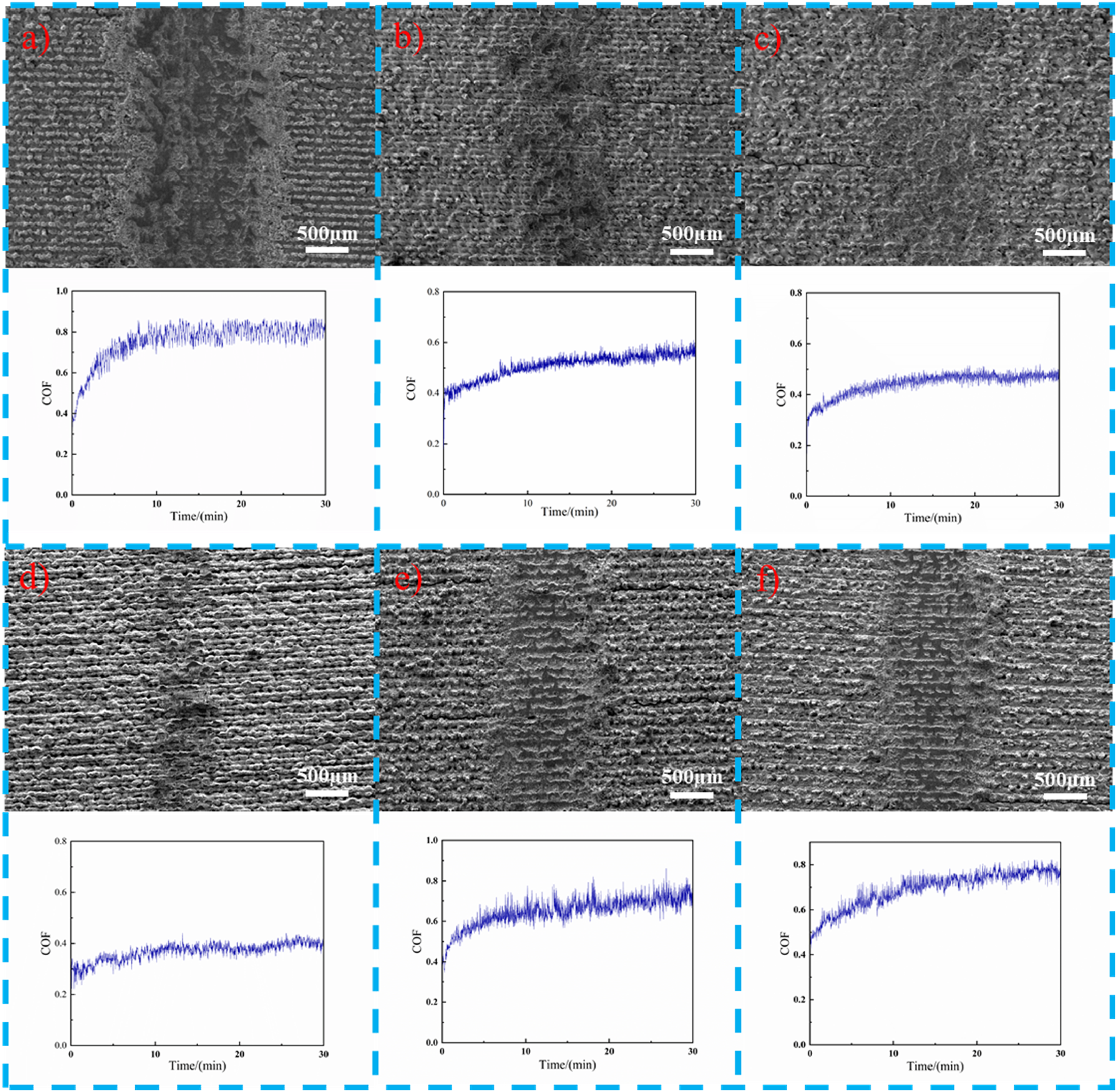
Surface wear scar morphology and friction coefficient curve of nitrided samples with different laser parameters. (a) S-1, (b)S-2,(c)S-3, (d)S-4,(e)S-5,(f)S-6.
Figure 7(a) to (f) presents the surface roughness measurements and 3D morphological profiles of wear tracks on nitrided samples processed under different laser parameters. The results indicate that under identical load and sliding duration, sample (S-1) exhibits the lowest roughness yet comparatively severe wear, whereas sample (S-4), with the highest roughness, demonstrates relatively mild wear. The surface roughness resulting from laser hybrid processing is significantly influenced by laser parameters and increases with the dimension of textured features.Surface roughness considerably affects the coefficient of friction (COF): excessively smooth surfaces lead to higher COF due to increased real contact area and strong adhesive forces. Conversely, excessively rough surfaces result in even higher COF and severe wear caused by abrasive ploughing and third-body wear induced by debris.25–26Within the parameter range applied in this study—laser power of 8–12 W and scan speed of 9–25 mm/s—the asperities on the nitrided surface effectively reduce adhesion, while the valleys accommodate wear debris. This enables the intrinsic low-adhesion characteristic of the nitride layer to dominate the tribological behavior.
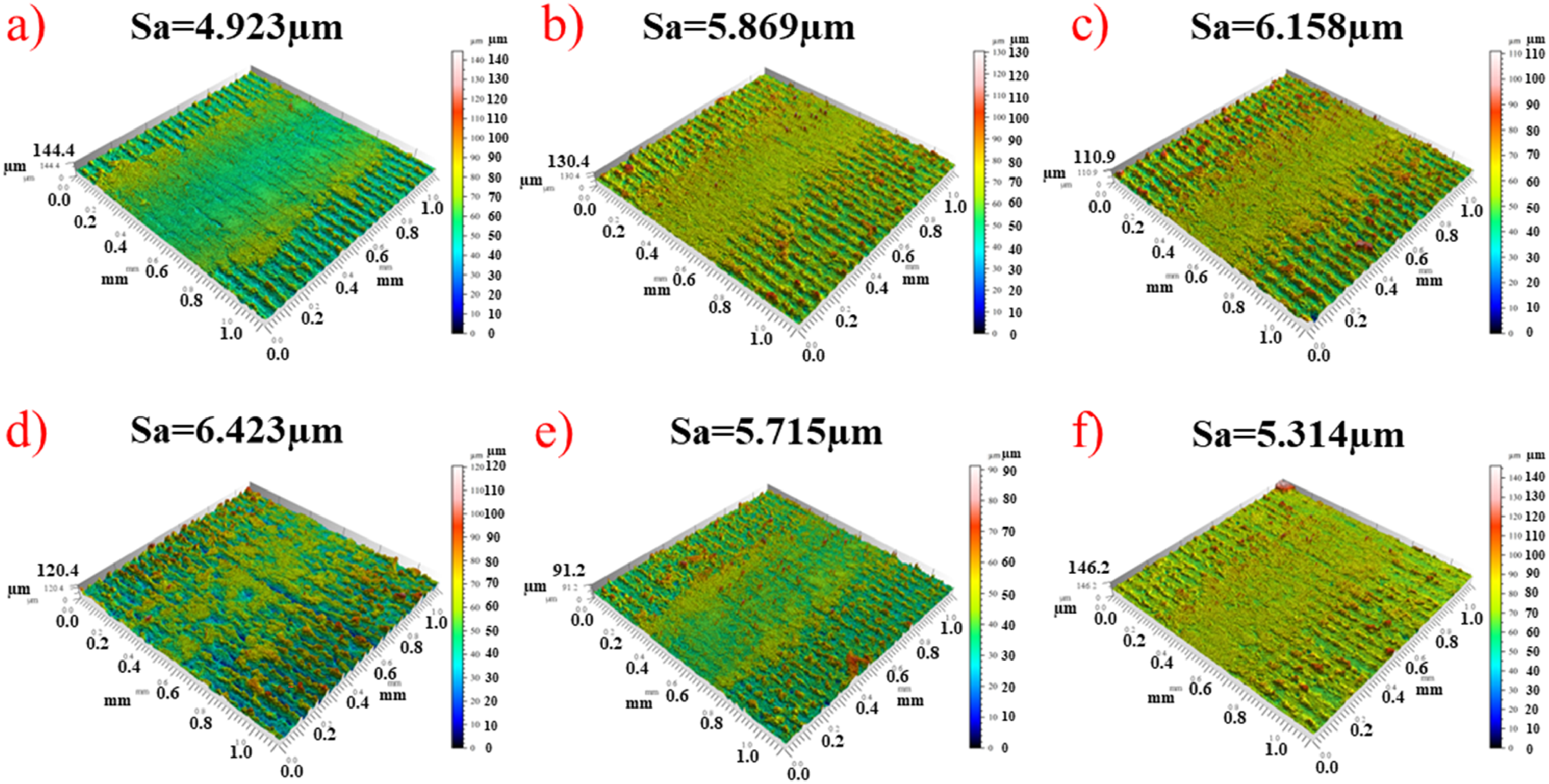
Surface roughness and 3D morphological profiles of laser-nitrided samples after wear testing: (a) S-1; (b) S-2; (c) S-3; (d) S-4; (e) S-5; (f) S-6.
Figure 8(a) presents the surface microhardness measurements of laser-nitrided samples. As the laser power increases from 8 W to 12 W, the surface hardness of the samples exhibits an increasing trend. Conversely, increasing the scanning speed from 9 mm/s to 25 mm/s results in a gradual decrease in surface hardness. Notably, the sample treated at 10 W laser power and 9 mm/s scanning speed (S-4) attained a maximum average microhardness of approximately 1380 HV0.2, representing an increase of about 1030 HV0.2 compared to the untreated substrate (S-0).
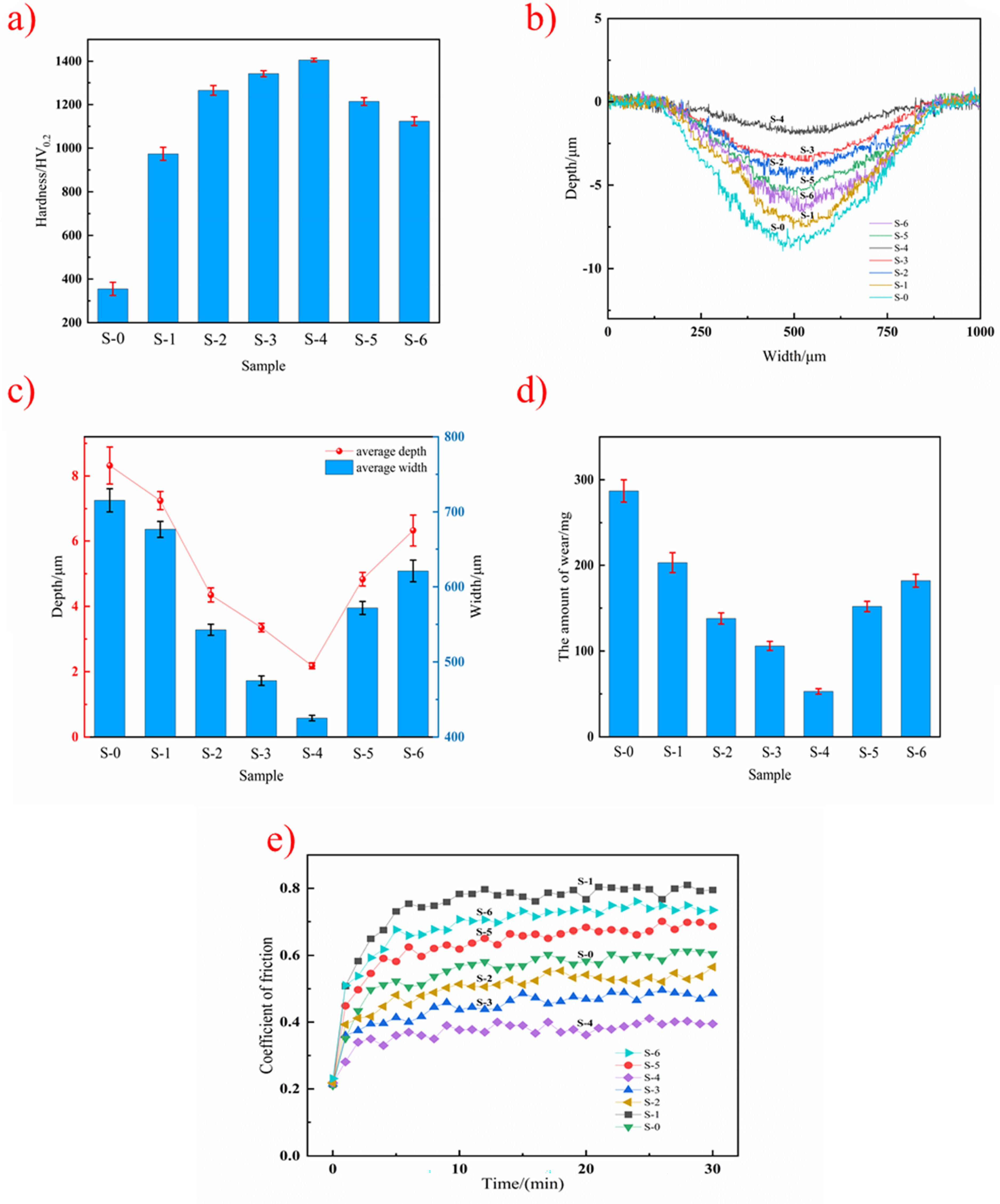
Analysis of surface wear resistance of Ti6Al4V after laser nitriding. (a) Surface hardness of nitrided samples. (b) The two-dimensional contour curve of the wear marks in the nitriding area. (c) Depth and width of wear marks on nitride samples. (d) Wear amount of nitride sample. (e) Trend chart of friction coefficient for nitride samples.
Figure 8(b) to (d) show the two-dimensional profiles of the wear tracks, along with the corresponding wear depth, width, and wear volume for the nitrided samples under different laser processing parameters. Under identical load and friction time conditions, the untreated substrate exhibited the most severe wear, with average wear depth, width, and volume reaching 8.3 μm, 715 μm, and 287 mg, respectively. Increasing the laser power resulted in a progressive reduction of these wear parameters. For example, at 12 W (S-3), the wear depth, width, and volume decreased to 3.35 μm, 475 μm, and 106 mg, respectively. Conversely, these wear metrics increased with increasing scanning speed. Among all tested conditions, the sample at 10 W and 9 mm/s (S-4) demonstrated the best wear resistance, with the smallest wear depth, width, and volume measured as 2.18 μm, 425 μm, and 53 mg, respectively.
Figure 8(e) illustrates the variation in friction coefficients of nitrided samples under different laser processing parameters. Under unlubricated conditions, the base material exhibited a friction coefficient of approximately 0.55, while the nitrided samples achieved a minimum friction coefficient of 0.35. As shown in Figure 8(e), some nitrided samples (S-1, S-5, S-6) displayed higher friction coefficients than the base material, whereas others (S-2, S-3, S-4) demonstrated lower values. This observation aligns with the findings of A. Bharatish et al., 27 who reported that laser-textured surfaces may exhibit higher friction coefficients than untreated substrates in certain cases.
The friction coefficient of the nitrided layer is influenced by multiple synergistic factors, including phase composition, crystal structure, surface morphology, and laser processing parameters. TiN exhibits high hardness but brittleness, providing strengthening and support to the substrate, while Ti₂N offers superior toughness. An increased proportion of Ti2N enhances toughness but reduces surface hardness. Laser energy density and nitrogen concentration are critical factors in TiN formation—higher energy density and nitrogen content promote TiN, whereas lower values favor Ti₂N. Additionally, laser scan passes significantly influence the microstructure. Multiple scans refine grains, and nanocrystalline/ultrafine-grained structures can improve toughness through grain boundary sliding. However, excessive grain refinement may increase brittleness.To optimize the phase ratio for balanced wear resistance and crack suppression, this study employed single-pass laser scanning under low energy density in a pure nitrogen atmosphere. This approach achieves a favorable compromise between wear resistance and mechanical properties by controlling TiN/Ti2N phase distribution.
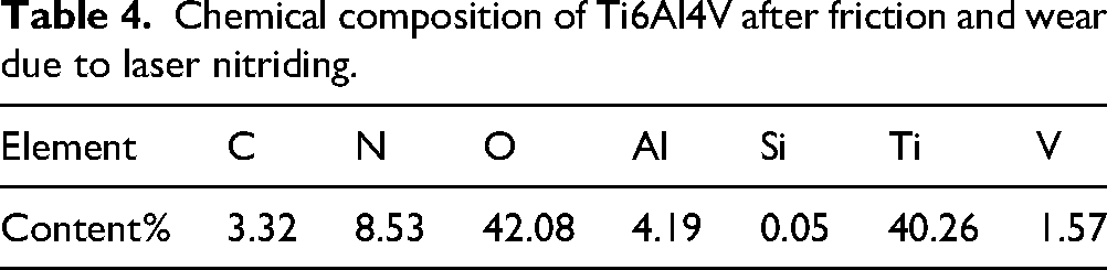
Figure 9(a) and (b) presents the elemental mapping (EDS) of the wear track region on sample (S-3) following the friction wear test, along with the corresponding surface elemental composition listed in Table 4. The results indicate that silicon (Si) is predominantly concentrated at the bottom region of the wear mark, while oxygen (O) is more uniformly distributed compared to the unworn nitrided surface. This suggests that Si-containing species adhered to the high-hardness nitrided surface beneath the frictional contact during wear. Moreover, the wear process involved oxidation reactions, leading to the formation of oxide compounds on the surface.
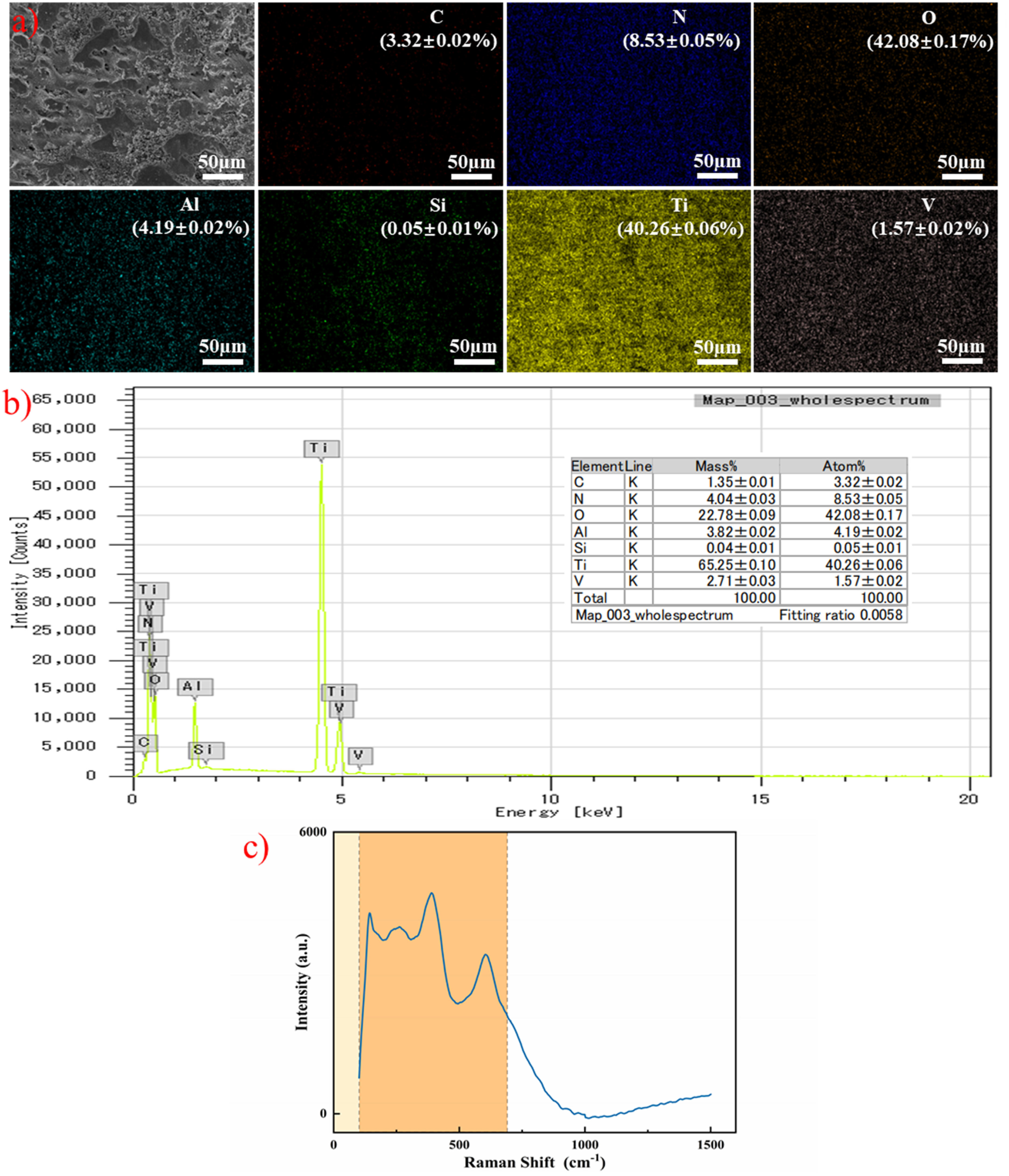
(a,b) EDS spectrum of wear scar area on nitrided surface. (c) Raman spectrum for the laser treated sample.
Chemical composition of Ti6Al4V after friction and wear due to laser nitriding.
To further verify the phase composition after wear, the laser-treated samples were characterized using Raman spectroscopy, with the results presented in Figure 9(c). The spectrum exhibits distinct Raman characteristic peaks, including a prominent peak at 143 cm−1 corresponding to rutile-type TiO₂ and peaks at 612 cm−1 attributed to oxidation products of TiN.V.V.Buranych et al. further demonstrated that the nitride-oxygen coatings possess a nanocrystalline structure characterized by a non-bonded state between nitride and oxide phases. Their results indicated that the nitrogen-enriched sample exhibits a (110)-oriented rutile crystalline structure with large cluster sizes reaching 124 nm. 28 Additionally, Magnéli phases were identified, manifested by: (i) minor peaks between 150–200 cm−1 resulting from Ti-Ti bond vibrations, and (ii) a second broad peak between 230–300 cm−1 associated with Ti-O vibrations. Specifically, the characteristic peaks at 250 cm−1, 242 cm−1, and 280 cm−1 correspond to the Ti2O3 phase. 29 The oxidation product Si3N4 was identified by its characteristic peak at 205 cm−1, originating from bending vibrations. Furthermore, the Raman peaks observed at 211 cm−1, 230 cm−1, and 576 cm−1 are assigned to the TiN phase. 29 This detection result further confirms the occurrence of oxidation reactions during the wear process and the generation of nitrides during laser nitriding.
Wear mechanisms
Figure 10(a) illustrates the abrasive wear morphology on the surface of the untreated Ti6Al4V substrate. The substrate predominantly exhibits severe abrasive wear, adhesive wear, and plastic deformation. During the sliding process, the Si₃N₄ friction ball ploughs into the relatively soft titanium alloy substrate surface, causing extensive plastic deformation and groove formation, as shown in Figure 10(b). Concurrently, bonding occurs on the substrate surface, as depicted in Figure 10(c). This phenomenon arises because the substrate surface undergoes reciprocating cyclic loading, leading to repeated contact that promotes work hardening, deformation, spalling, and the formation of pits. The spalled material readily adheres to the friction interface, contributing to secondary abrasive wear and the development of ploughing grooves.
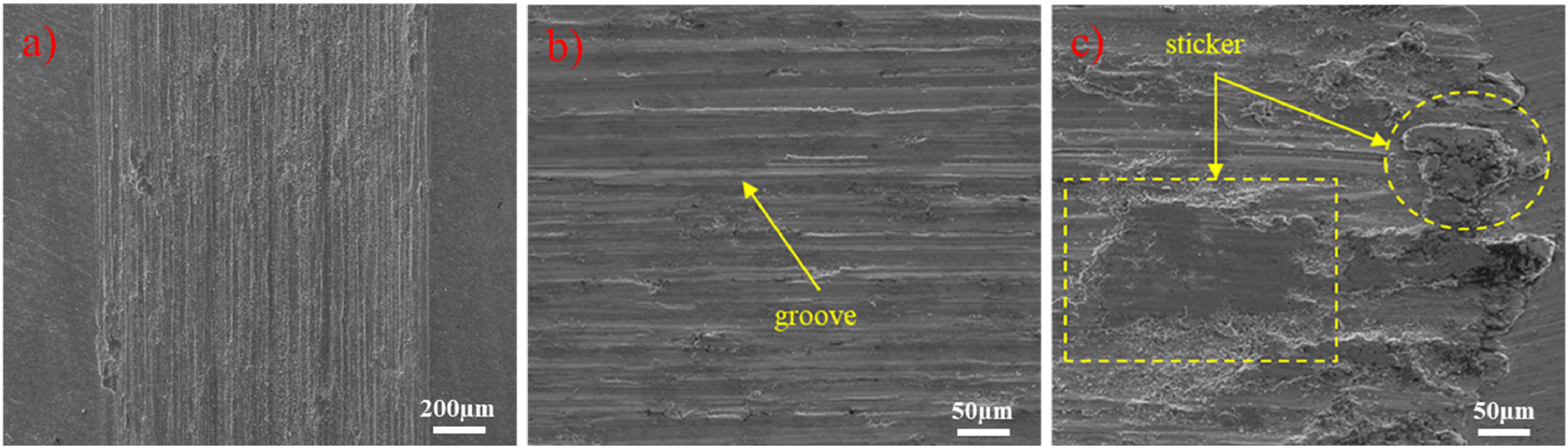
(a) Wear scar morphology of Ti6Al4V substrate surface. (b) Micro morphology of wear mark groove. (c) Micro morphology of wear mark sticker.
Figure 11 presents the micro-morphology of abrasion marks on nitrided Ti6Al4V surfaces processed under different laser parameters. Under a nitrogen atmosphere, laser ablation forms a periodic array of grooves, creating peaks and valleys on the substrate surface. During friction, the peaks directly contact the counterface and undergo abrasion, while the valleys act as reservoirs for abrasive debris, as shown in Figure 11(e). Compared to the substrate, the nitrided surface exhibits reduced ploughing and adhesion phenomena, indicating that abrasive wear, adhesive wear, and their combined mixed wear are effectively mitigated by laser nitriding. This improvement is attributed to the formation of titanium nitride a hard ceramic phase that reinforces and supports the substrate. Furthermore, the periodic grooves and valleys contribute to the reduction of abrasive wear by trapping debris.

Micro morphology of wear marks on nitrided surface under different laser parameters. (a) S-1, (b) S-2, (c) S-3, (d) S-4, (e) S-5, (f) S-6.
However, the relatively poor toughness of titanium nitride in the nitrided layer leads to brittle fracture during friction, resulting in localized adhesion as observed in Figure 11(a) and (f). Consequently, some degree of abrasive and adhesive wear still occurs on the nitrided surface. Figure 11(b) to (d) illustrate abrasive scar surfaces exhibiting friction coefficients lower than that of the untreated substrate, where the dominant wear mechanisms are mild adhesive wear and plastic deformation. Abrasive debris is primarily generated through repeated rolling interactions between the nitrided surface and the counterface. Additionally, parts of the nitrided material experience a transition from typical plastic deformation to brittle fracture, producing wear debris.
The corrugated surface texture observed on nitrided samples, exemplified in Figure 11(c) and (d), originates from instabilities associated with the Marangoni effect during processing. These surface features serve to trap wear debris, preventing its participation in friction and adhesion, while also increasing local contact stresses, thereby reducing both abrasive and adhesive wear. The formation of troughs and ripples on the nitrided surface thus provides dual storage of wear debris, significantly enhancing the wear resistance of the treated material.This finding is consistent with the results reported by L.G.Zhurerova et al., 30 who demonstrated that surface treatment of 30CrMnSiA steel under low-temperature plasma conditions leads to the in-situ formation of fine, hard carbide and carbonitride particles. These precipitates act as “pinning” reinforcements that significantly enhance the surface properties by strengthening the material's superficial layer.
Quality calibration analysis of DM code marking
To investigate the effect of different laser processing parameters on the quality of DM code reading under a nitrogen atmosphere, DM codes were marked on the surface of Ti6Al4V alloy using the parameters listed in Table 1. The quality of the DM codes formed under pure nitrogen was evaluated using a DM code calibrator. Figure 12(a) shows the contrast of nitrided DM code modules produced under different laser conditions. Module contrast, defined as the brightness difference between adjacent units in the DM code image, is a critical metric for assessing code readability as it directly impacts decoding accuracy. Insufficient contrast between neighboring modules can cause the decoder to misidentify module boundaries, leading to decoding errors or failure.The laser-nitrided DM codes were created on a polished Ti6Al4V surface, where the nitride marking exhibited varying degrees of yellow chromaticity, contrasting strongly with the silver-white substrate, as visible in Figure 12(a). As the laser parameters vary, the module contrast shows a trend of initially increasing and then decreasing, with an average module contrast of 48.13%. This value meets the minimum contrast requirements for reliable DM code recognition.
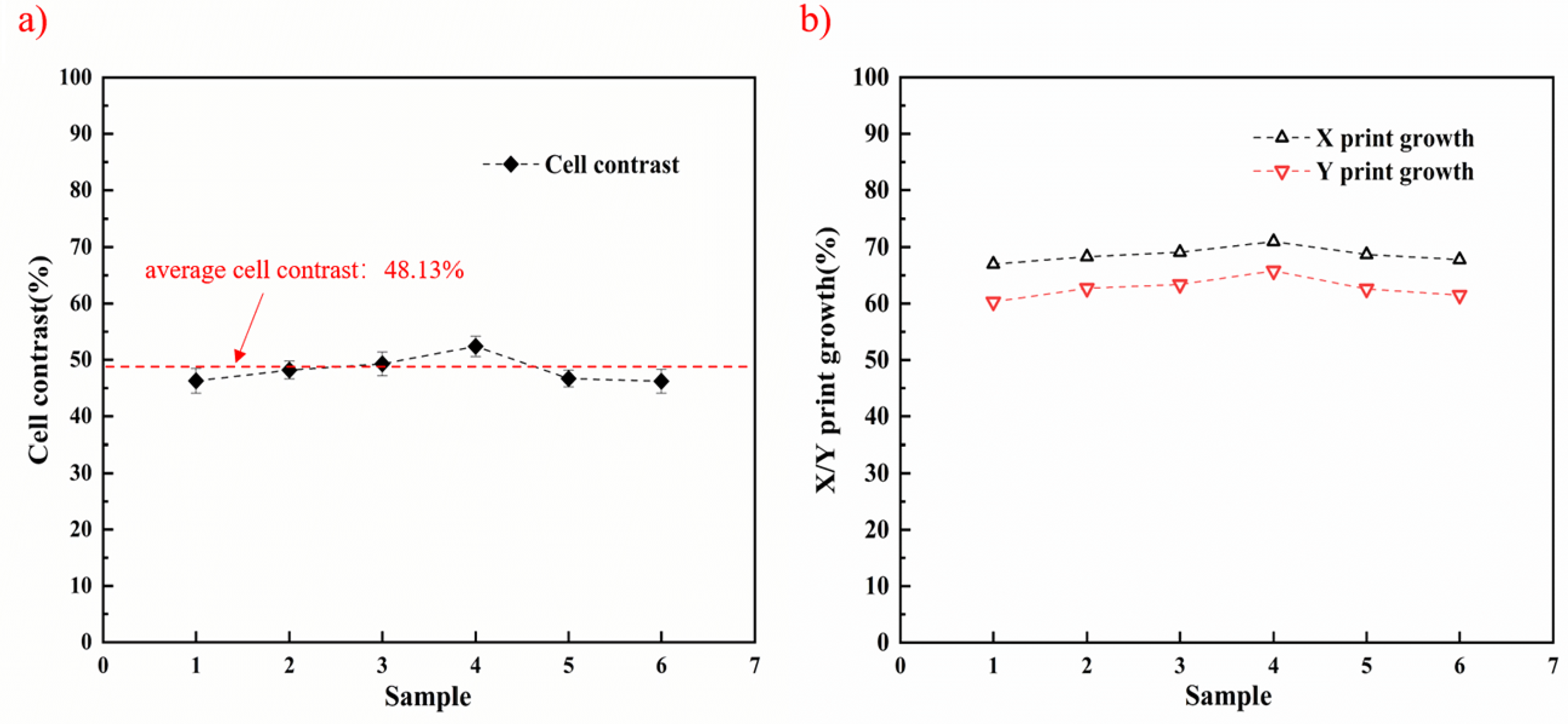
(a) Contrast of nitrided QR code module with different laser parameters. (b)Printing growth of nitrided two-dimensional code with different laser parameters in X and Y directions.
Figure 12(b) illustrates the printing growth ratio of the nitrided DM codes in the X and Y directions across different laser parameters. This ratio represents the relative width and height of the dark and light modules within the DM code. During laser marking, edge thermal effects can cause the actual dark module area to be larger than the ideal size, resulting in printing growth—where the dark module expands beyond its intended dimensions thus degrading code quality and potentially hindering readability.As shown in the figure, the X-direction printing growth for all laser-nitrided DM codes remains below 70%, with an increase of no more than 20% relative to the ideal 50%, which is acceptable. The Y-direction printing growth remains under 20%, indicating that the dimensional difference between dark and light modules is small. This moderate printing growth in both directions is favorable for maintaining DM code readability.
Table 1 presents the parameters used for the engraved DM codes quality verification. Among the samples, the DM code quality level of sample (S-4) was rated as grade B, while all other samples achieved grade A, indicating that the marking quality meets the industrial standards required for DM code readability. However, considering the presence of complex operating environments such as oil contamination and abrasive debris, the surface reading quality of DM codes may degrade or become unreadable.Taking into account the abrasion resistance performance of the DM code surfaces, sample (S-3) marked with a laser power of 10 W, scanning speed of 15 mm/s, and line spacing of 0.03 mm was selected as the optimal processing parameter for application on engine compressor blades, as shown in Figure 13. This parameter combination not only ensures excellent DM code readability for turbine blade identification but also guarantees reliable performance in harsh operational conditions.
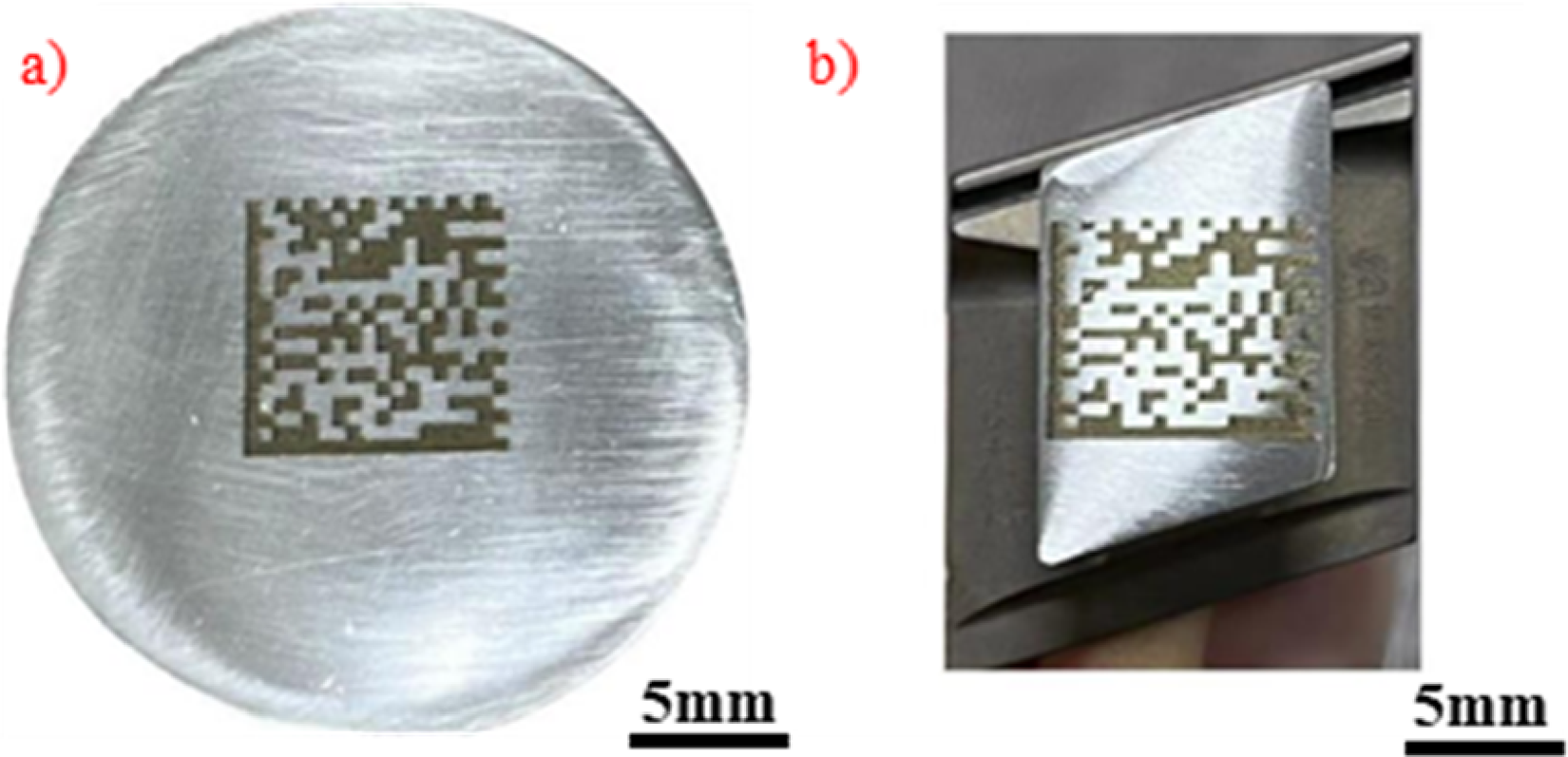
Laser nitriding DM code marking on Ti6Al4V substrate and turbine blade.
To further evaluate the mechanical durability of the DM codes, rigorous wear testing was performed on the laser-marked samples using the experimental setup illustrated in Figure 14(a). As evidenced by the analytical results in Figure 14(b), the tested specimens exhibited remarkable wear resistance, maintaining stable DM code contrast and class A readability without significant degradation even after being subjected to extensive wear distances up to 2000 cm. These findings robustly demonstrate the reliability and feasibility of laser gas nitriding technology for DM code marking applications.
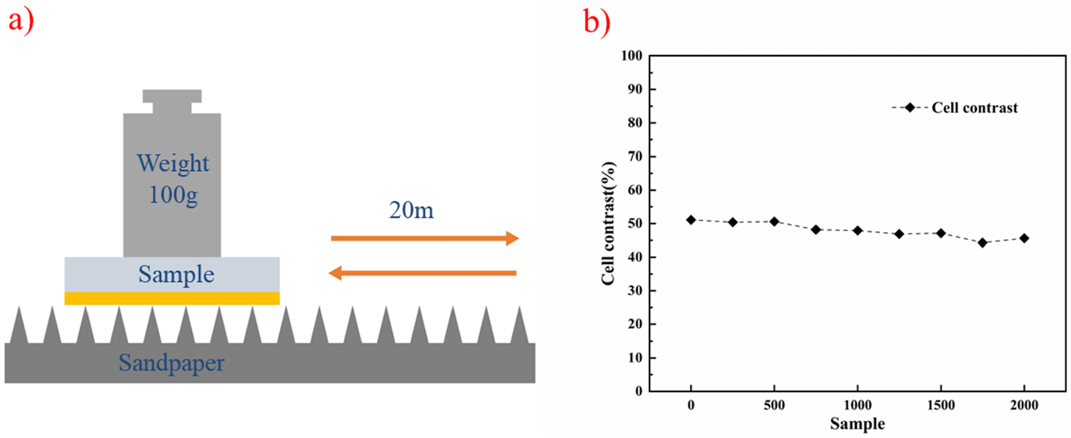
Mechanical durability test of the surface of the DM code:a) Schematic of sandpaper abrasion b) Cell contrast versus abrasion distance.
Conclusions
In this paper, the effects of different laser parameters on the wear resistance and DM code marking quality of nitrided titanium alloy surfaces were systematically investigated. Ti6Al4V surfaces were nitrided and textured using a nanosecond pulsed laser under a nitrogen atmosphere. The main conclusions drawn from the experiments and analyses are as follows:
A periodic textured structure was successfully fabricated on the Ti6Al4V surface under nitrogen atmosphere. Laser nitriding treatment significantly enhanced the wear resistance compared to the untreated substrate, with surface microhardness reaching approximately 1300 HV0.2, representing a threefold increase relative to the base material. The untreated Ti6Al4V substrate surface primarily suffered from severe abrasive wear, adhesive wear, and plastic deformation during friction. The formation of high-hardness titanium nitride (TiN) on the laser-nitrided surface acted as a reinforcement and support to the substrate. Additionally, the peaks, valleys, and corrugated surface texture created by laser processing served as dual reservoirs for wear debris, transforming the dominant wear mechanisms to mild adhesive wear accompanied by limited deformation. The contrast of the DM code modules marked under nitrogen atmosphere, as well as the print growth in both X and Y directions, remained within stable intervals. The minimal size difference between dark and light modules in the nitrided DM codes contributed to both excellent abrasion resistance and superior readability.
Footnotes
Author contribution(s)
Funding
This work was supported by the National Natural Science Foundation of China (General Program)(52475475), the “Scientists + Engineers” Team Building Project of Qinchuangyuan in Shaanxi Province (2024QCY-KXJ-192).
Declaration of conflicting interests
The authors declared no potential conflicts of interest with respect to the research, authorship, and/or publication of this article.
Data availability statement
Data underlying the results presented in this paper are not publicly available at this time but may be obtained from the authors upon reasonable request.