
Abstract
Cavitation causes rapid surface degradation, material loss, and reduced service life in propellers and other marine components, making it a critical operational challenge. AISI 420 stainless steel, commonly used in small vessel propellers and industrial equipment, is especially vulnerable under such conditions. In this work, the wear resistance of AISI 420 was improved by applying a microwave-processed composite cladding. Nickel powder reinforced with molybdenum was deposited onto the steel surface using microwave hybrid heating, a process that provides uniform heating and strong metallurgical bonding. The clads were studied using SEM/EDS and XRD, and their porosity and hardness were carefully measured. The treated surface showed nearly double the hardness compared to the base metal, increasing from about 310 ± 20 HV for the substrate to 591.53 ± 20 HV after cladding. Cavitation tests using a vibratory erosion setup confirmed that this improvement translated into better real-world performance. The reinforced cladding significantly improved cavitation erosion resistance, reducing the erosion rate to 16.1%, a threefold improvement over the untreated clad (49.43%). SEM analysis of the eroded surfaces revealed characteristic damage features, including pits, craters, micro-cracks, and plastic deformation, and confirmed that reinforcement induced a transition from ductile to brittle wear behavior.
Introduction
Marine propellers are vital parts of ships because they transfer engine power to produce thrust. They operate in challenging conditions such as corrosion, cavitation, and marine fouling. 1 Problems with these parts can cause costly downtime and repairs. Common failure modes observed in research include cavitation-induced torsional fatigue, stress corrosion cracking, and corrosion fatigue. Cavitation is a major issue in marine settings. It happens when local liquid pressure drops below vapor pressure, forming vapor bubbles that grow and burst violently. 2 In rotating parts like propellers and impellers, cavitation intensity increases with speed. On a propeller, it mainly occurs on the suction side of the blade, where cavities collapse as pressure rises, creating shock waves that lead to erosion, noise, and vibration. 3 Over time, this reduces propulsion efficiency and can cause blade fatigue failure. To prevent these problems, propellers are regularly inspected and maintained. However, smaller ships like fishing boats often use basic propeller designs that do not account for cavitation resistance. This results in more cavitation, higher fuel use, and frequent maintenance costs. Cavitation damage commonly occurs on the leading and trailing edges of propeller blades, guide vanes, and hull parts usually made from austenitic or martensitic stainless steels. 4 Due to their insufficient hardness, these steels are especially prone to erosion. Most research on cavitation erosion relies on ultrasonic testing following ASTM G-32 standards instead of full-scale sea trials. Large-scale testing is difficult because of operational challenges, so researchers typically use model propellers in cavitation tunnels or open-water setups to study inception, noise, and vibration. These challenges have led to efforts to develop materials with better resistance to cavitation and techniques like coating and cladding surface modifications. 5 Many studies report that applying protective layers to stainless steel substrates greatly improves cavitation erosion resistance.
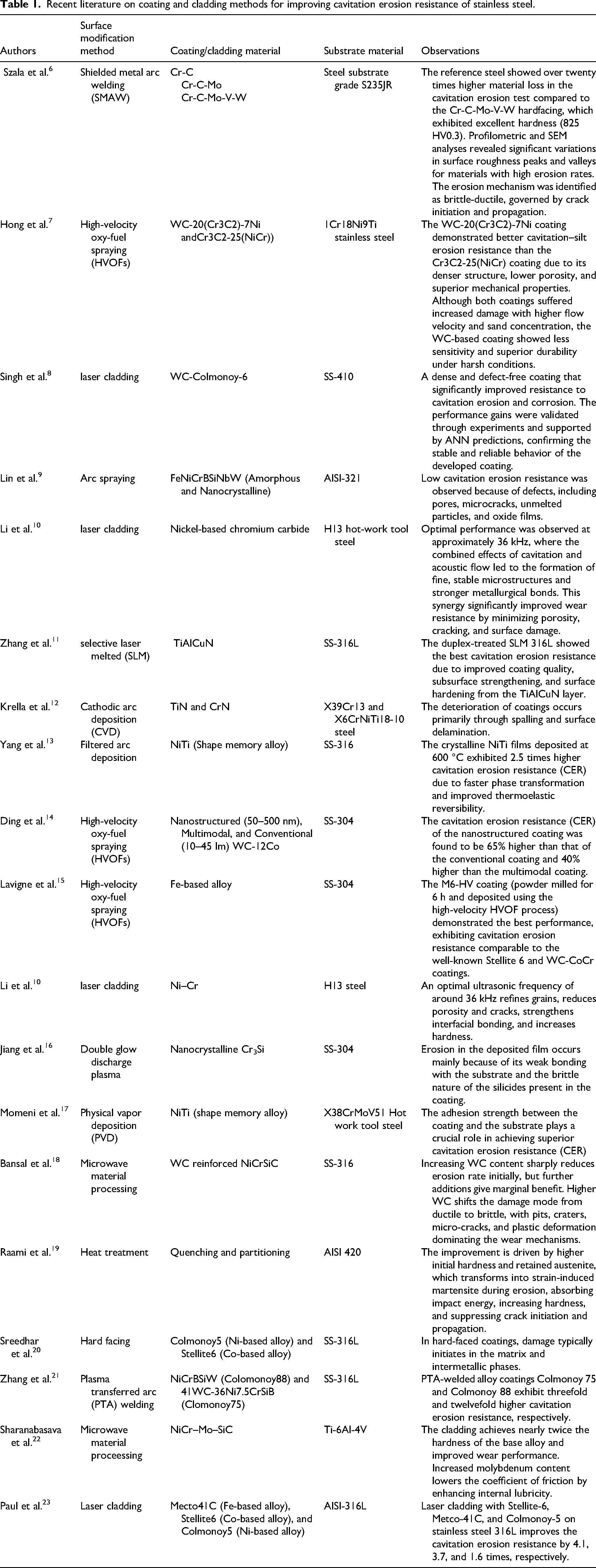
The literature review (Table 1) identifies commonly used surface modification techniques, including high-velocity oxy-fuel (HVOF), physical vapor deposition (PVD), chemical vapor deposition (CVD), laser cladding, plasma transferred arc (PTA), and conventional welding. Thermal spraying methods such as HVOF demonstrate efficiency but are often limited by reduced metallurgical bonding and increased porosity, which can decrease toughness and result in particle detachment under cavitation loading. In contrast, fusion-based techniques such as laser cladding and PTA provide improved bonding, although they may introduce significant thermal gradients and dilution effects. PVD and CVD processes require high vacuum and temperature conditions, along with skilled operators. Their coating deposition rates are relatively slow, and additional cooling systems are necessary to manage the large amount of heat generated. 24 Despite being a well-developed surface modification method, laser cladding also has certain drawbacks, including high setup costs, significant power demand, thermal distortion, residual stresses, and steep thermal gradients caused by the intense heat source. 25 Cracks may also form on the clad surface and at the interface due to rapid cooling. 26 Similarly, in conventional welding, excessive dilution and severe substrate deformation are common, often leading to crack formation during solidification. These defects, along with the dissolution of hard particles, ultimately degrade the mechanical properties and cavitation erosion resistance of the cladding. 27
Recent literature on coating and cladding methods for improving cavitation erosion resistance of stainless steel.
The main limitations of traditional surface modification techniques stem from their heating sources, such as laser beams in laser cladding and flame or arc energy in spraying and welding. 28 In these methods, heat is transferred to the material through conduction, convection, and radiation, causing rapid solidification under a high thermal gradient. 29 The heat transfer behavior depends largely on the material's thermal properties, including conductivity, heat transfer coefficient, and emissivity, which ultimately influence the quality of the cladding. 30 Microwave hybrid heating (MHH) offers a potential alternative with advantages such as controlled, volumetric heating and improved energy efficiency. However, direct comparative studies under identical conditions remain limited. 31
In 2010, Gupta and Sharma patented a microwave hybrid heating (MHH) based cladding process for applying both metallic and non-metallic materials onto metallic substrates. Since then, several researchers have shown that microwave cladding using hybrid or bidirectional heating provides superior properties compared to conventional methods. 32 Studies have explored microwave cladding on various steels such as SS 304, 33 SS 316, and SS 420, using nickel- and cobalt-based matrices. 34 To enhance hardness, ceramic reinforcements like boron carbide (B₄C), chromium carbide (Cr₃C₂), tungsten carbide (WC), alumina (Al₂O₃), and silicon carbide (SiC) have been widely incorporated.35,36
Microwave-developed clads exhibit enhanced sliding wear resistance, increased resistance to slurry and abrasive erosion, and superior performance against solid particle erosion. Despite these advancements, research specifically addressing cavitation erosion resistance (CER) via microwave cladding remains limited. Babu et al. were the first to investigate this area, developing Ni–SiC composite clads (nano, micro, and bimodal) on SS 316L substrates. Their findings indicate that bimodal coatings with 10% SiC (comprising 5% nano-SiC and 5% micro-SiC) achieved up to five times greater CER compared to bare SS 316L. 37 Additionally, these microwave-processed claddings surpassed thermally sprayed Stellite 6 and WC–10Co–4Cr coatings due to lower porosity, higher fracture toughness, and increased hardness. 38
Building on the promising results of previous studies, the present research investigates the application of microwave cladding to develop cavitation-resistant coatings on stainless steel substrates.39,40 The study emphasizes the development, characterization, and assessment of cavitation erosion behavior in a microwave-processed Ni-5Mo composite clad. As cavitation erosion resistance (CER) is strongly associated with surface hardness, and hardness typically increases with greater reinforcement content, a higher Mo proportion (5 wt%) is utilized in this work. The subsequent sections detail the material selection, processing methodology, characterization, and evaluation of cavitation erosion.
Experimental studies
Substrate and cladding material
Selecting appropriate materials presents a significant challenge in enhancing the surface properties of substrates with limited cavitation erosion resistance (CER). Martensitic stainless steel grade SS-420 was selected for this study based on its turbo machinery application 41 and intrinsic properties and their interactions with low-frequency microwave radiation. Cavitation resistance primarily depends on a material's hardness and ductility, which determine its capacity to absorb impact energy during bubble collapse. Enhancing one property often compromises the other, as increased ductility and toughness typically result in reduced hardness. This trade-off can be mitigated by employing composite materials, which enable a balanced combinatio 33 n of hardness, ductility, and toughness through the optimal pairing of matrix and reinforcement. Fe-based amorphous alloys are often considered promising matrix materials for improving cavitation resistance because they offer excellent glass-forming ability, high hardness, and relatively low cost. 42 However, their poor corrosion resistance limits their use in aggressive environments. In contrast, Mo and Ni-based alloys provide superior corrosion protection, making them suitable for marine and high-temperature applications. Despite this, cobalt is expensive and poses health concerns due to its carcinogenic and radioactive nature. 43 Comparatively, all three alloy systems Fe, Co, and Ni exhibit similar stacking fault energies. In earlier research, processing metallic materials with microwaves was challenging because of their low microwave absorption, but hybrid heating techniques have made it feasible today. Considering these factors, a commercially available Ni-based alloy powder (EWAC 1004EN) was selected as the matrix material due to its excellent resistance to wear, corrosion, and oxidation, along with its widespread use in marine, power, and aerospace industries. The substrate material was procured from Jaydeep Metals Pvt. Ltd (Mumbai, India). For the coating material, we employed commercially available EWAC 1004EN (Ni-based) powder sourced from Ewac Alloys Pvt. Ltd (Mumbai, India).
The reinforcement phase plays a key role in enhancing the hardness, toughness, and strength of the metal matrix composite. Refractory carbides, nitrides, and borides are commonly used for this purpose because of their excellent mechanical and thermal stability. In microwave material processing, certain ceramics also stand out for their strong microwave absorption ability, which promotes efficient heating. Studies have widely reported the use of hard reinforcements such as tungsten carbide (WC), silicon carbide (SiC), titanium carbide (TiC), chromium boride (CrB₂), titanium nitride (TiN), and chromium nitride (CrN) in cavitation erosion-resistant coatings and claddings. 44
However, refractory metals like molybdenum (Mo) have been explored only in limited studies, despite their promising potential. 45 Considering these factors, commercially available molybdenum (Mo) powder was selected as the reinforcement material for this study. Molybdenum also provides excellent corrosion and oxidation resistance, maintaining stability up to about 900 °C. The materials were sourced from reliable suppliers in New Delhi India.
Characterization of raw powders and bulk material
Material characterization is essential for understanding behavior during processing. Scanning electron microscopy (SEM), optical microscopy (OM), energy-dispersive spectroscopy (EDS), and X-ray diffraction (XRD) were employed to assess the purity and morphology of the powders. 46 The microstructure, phase composition, and properties of the raw materials were comprehensively characterized using XRD, SEM, and EDS mapping. Figures 1–2 and Tables 2–3 present the detailed results of these characterizations, including the physical, mechanical, and chemical properties essential for understanding the material behavior before microwave processing. EWAC powder displayed a typical spherical morphology, indicating ductility, while molybdenum powder exhibited sharp-edged particles, characteristic of hard and brittle materials. The average particle sizes were approximately 30 ± 10 µm for EWAC and 40 ± 10 µm for molybdenum. Figure 1(b) shows that nickel is the dominant phase in the EWAC powder, with minor traces of chromium, silicon, and carbon. Figure 1(d) confirms that Mo is the sole phase in the molybdenum powder.
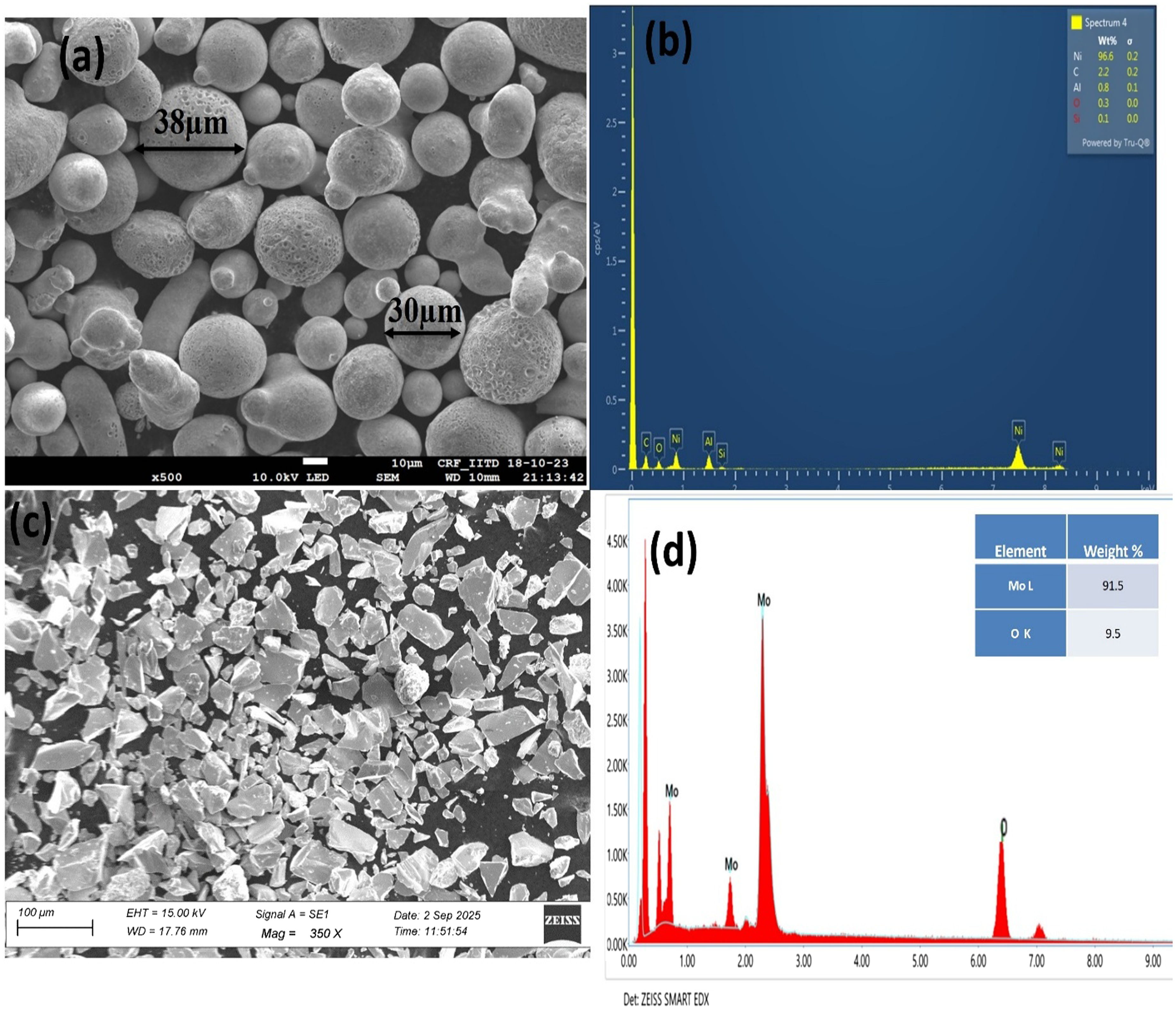
SEM and EDS mapping of clad powder: (a) niCrSiC powder (b) EDS mapping of NiCrSiC powder (c) molybdenum (Mo) powder and (d) EDS mapping of molybdenum powder.
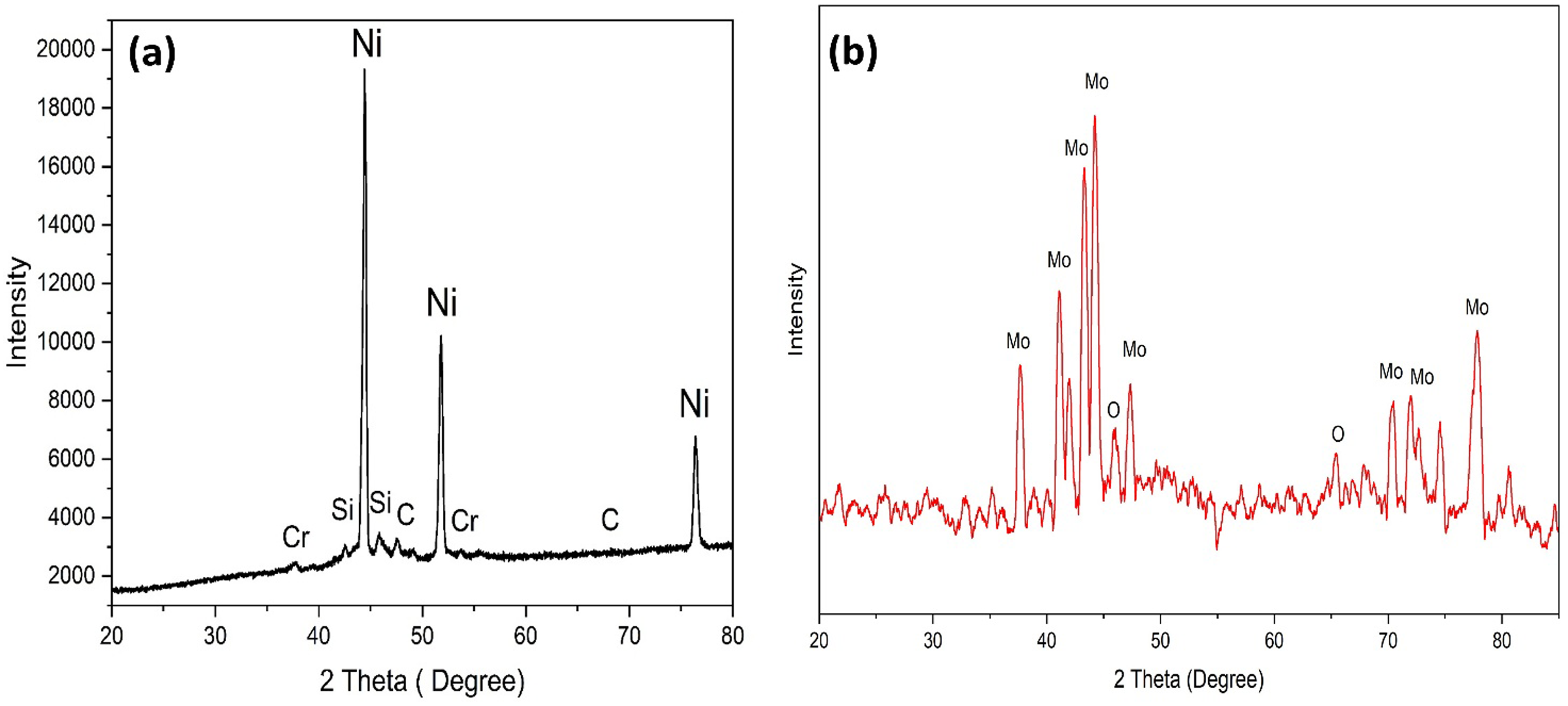
XRD analysis of clad powder: (a) NiCrSiC and (b) molybdenum (Mo).
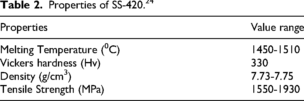
Properties of SS-420. 24
The substrate and clad powders’ chemical properties (weight percentage).

Development of clad
Powder preparation
Before cladding, the metal matrix and hard reinforcement powders must be properly blended to ensure uniform properties in the developed clad. In this study, Ni-based EWAC powder (NiCrSiC) and 5% (% by weight) molybdenum powder were mixed in a mechanical blender for 15 h at 30 rpm, as optimized in previous studies. 47 To prevent defects during cladding, the powder mixture was thoroughly dried to remove any moisture. For this purpose, the blended powder was placed in a graphite-coated crucible and preheated in a domestic microwave oven at 180°C for 24 h in convection mode.
Substrate preparation
SS-420 material was supplied as a flat bar with a 40 × 4 mm2 cross-section. Two specimen sizes were machined from this bar using an abrasive hand cutter: 10 × 10 × 4 mm3 for metallurgical characterization and 15 × 15 × 4 mm3 for cavitation testing, following ASTM G32–17. Burrs were removed with a belt grinder after cutting. The specimen surfaces were subsequently ground with 220 and 600-grit emery papers to eliminate oxide layers and to create a slightly rough surface, thereby improving adhesion between the substrate and the clad layer.
Microwave processing
The microwave cladding process in the present study is based on the principle of microwave hybrid heating (MHH). Initially, the metallic powder layer does not effectively absorb microwave energy due to its low skin depth at room temperature. 48 High-grade charcoal was selected as the susceptor; however, its initial coarse form was unsuitable for microwave hybrid heating (MHH). The charcoal was manually crushed and subsequently ground to produce fine particles. A fixed quantity of this fine charcoal powder was utilized in all experiments to ensure consistent heating. The powder was sieved to achieve a uniform particle size and positioned around the sample to enhance microwave absorption and heat transfer. Charcoal was chosen due to its high skin depth (greater than 35 mm at 2.45 GHz) and its effective microwave energy absorption. 49 A 1 mm-thick graphite sheet with a skin depth of approximately 0.12 m was used as an intermediate layer to prevent direct contact and contamination between the susceptor and the cladding material. This transition enables direct coupling of the material with microwave energy, resulting in volumetric heating, reduced thermal gradients, and enhanced diffusion across the clad–substrate interface. 50 This mechanism facilitates the formation of a dense and uniform clad with improved metallurgical bonding. For the present study, a NiCrSiC–5Mo composite powder was selected for cladding using a domestic microwave applicator operating at 2.45 GHz with a power of 900 W. A preplaced powder layer of approximately 1 mm thickness was uniformly deposited on the SS-420 substrate. A graphite separator sheet was placed above the powder layer to prevent direct interaction with the susceptor and to ensure controlled heating. 51 The entire assembly was then positioned on a refractory brick inside the microwave cavity, and charcoal powder was used as a susceptor to initiate and sustain the heating process. A schematic representation along with the actual experimental setup is shown in Figure 3, while the optimized processing parameters for the NiCrSiC–5Mo composite clad are summarized in Table 4. The detailed mechanism of microwave hybrid heating and the optimization approach adopted for process parameters have been discussed in our earlier studies. 5
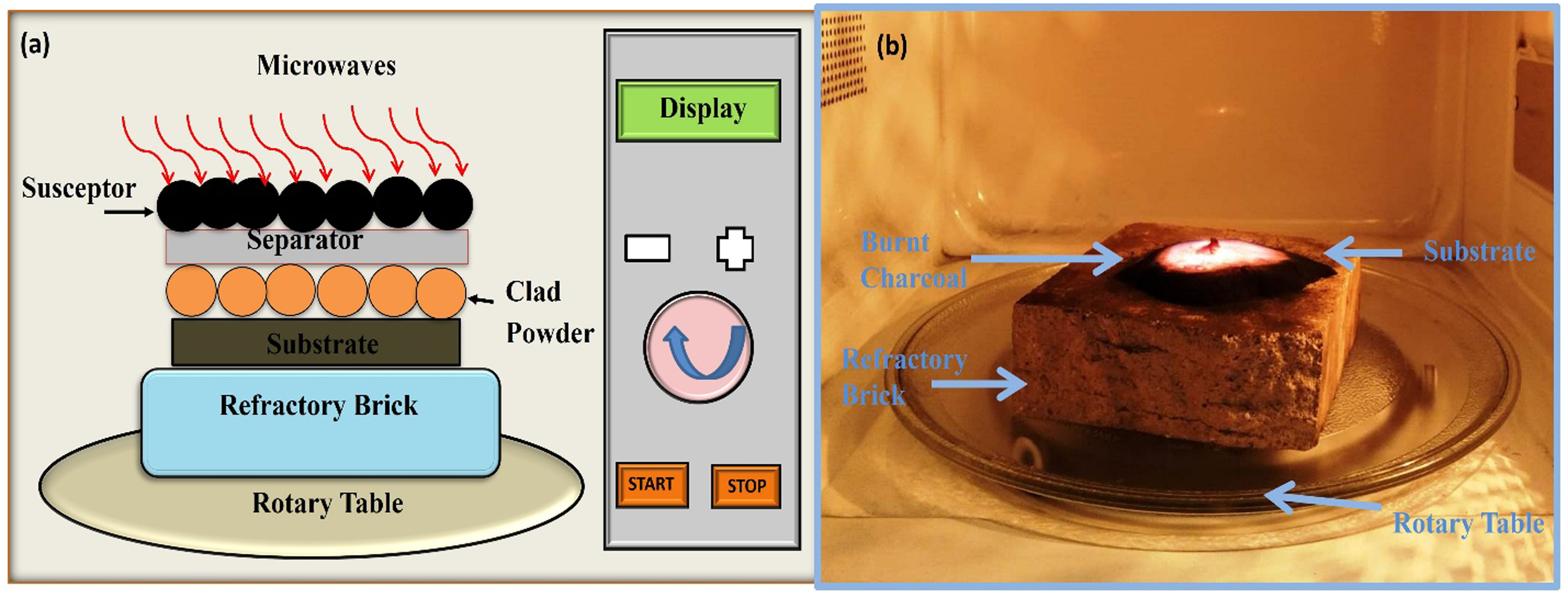
Microwave cladding process: (a) schematic diagram; (b) experimental setup.
Optimization of parameters for microwave cladding in clad development.
Characterization of composite cladding
Sample preparation
Clad specimens measuring 10 × 10 mm2 were sectioned through their thickness using a low-speed diamond saw cutter (Chennai Metco LSS003, India). The diamond-wafering blade enabled precise cuts with minimal specimen damage and an excellent surface finish. Cross-sections were manually polished with emery papers of 100, 220, 600, and 800 grits to eliminate deep scratches and prepare the surfaces for subsequent analysis. Further polishing was performed using a disc polisher with two rotating wheels. The first wheel was fitted with fine-grade emery papers ranging from 1000 to 3000 grit, applied sequentially. The second wheel was covered with a soft velvet cloth uniformly coated with diamond paste of 1 μm particle size. A diamond-lapping compound was sprayed onto the cloth to retain the polishing paste. This process produced a mirror-like, scratch-free surface, facilitating clear observation of the microstructure.
Metallurgical characterization
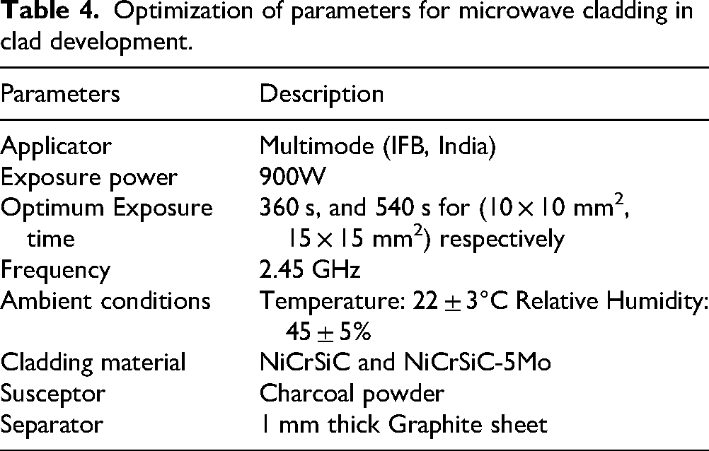
Polished specimens were examined for microstructure and chemical composition using a scanning electron microscope (SEM; JEOL Ltd, Tokyo, Japan, Model: JSM-650LV) and energy-dispersive spectroscopy (EDS). The transverse section of the clad was analyzed with a backscattered electron (BSE) detector at an accelerating voltage of 15 kV. Porosity was measured according to ASTM-B276-05 using an optical microscope (Radical Scientific Equipment, India, Model: RMM-8T) equipped with a digital camera and Micro Cam 4.1 software. The crystal structure of the developed clad was analyzed using an X-ray diffractometer (Rigaku Corporation, Tokyo, Japan, Model: SmartLab 9 kW) with Cu-Kα radiation, operated at 45 kV and 40 mA. Scanning was conducted at a rate of 1° per minute over a 2θ range of 10° to 100°. Phase identification was performed using X’Pert HighScore 2.2 software with the ICDD database, matching diffraction angles to four decimal places. The phases present in the NiCrSiC-5Mo composite clad were quantified using the normalized intensity ratio (NIR) method, calculated as described in Equation (1).
52
In this context, I₁, I₂, … Iₙ denote the intensities of the selected diffraction peaks, while I back refers to the background intensity. The Normalized Intensity Ratio (NIR) method offers a semi-quantitative approach for assessing phase composition however, it is not suitable for precise quantification. The accuracy of this method may be affected by experimental variability, peak overlap, matrix effects, and reliance on reference standards that do not fully account for material heterogeneity. Despite these limitations, NIR values remain effective for comparative evaluation, trend analysis, and rapid characterization, providing valuable insights into phase distribution, compositional changes, and reaction progression when relative behavior is prioritized over absolute values. 52
Mechanical characterization
The microhardness of the developed clad was measured along its cross-section using a Vickers microhardness tester (Shimadzu Corporation, Model 162-6938918-1) in accordance with ASTM E92-17. Indentations were made under a load of 300 g with a dwell time of 20 s. Measurements were taken at 80 μm intervals starting from the top of the clad surface. For each location, three readings were recorded (100 μm left and 100 μm right) to ensure high accuracy.
Cavitation erosion studies
Method selection
Two primary techniques are widely utilized for cavitation erosion testing: the vibratory (ultrasonic) method and the cavitating liquid jet method. 53 The American Society for Testing and Materials (ASTM) has standardized these procedures as ASTM G32-17 and ASTM G134-17, respectively. Of these, ASTM G32-17, which uses a vibratory (acoustic) cavitation apparatus, is the most prevalent for evaluating materials and surface coatings. This method specifies fixed parameters, including sample dimensions, vibration amplitude, frequency, test liquid, and container geometry, to ensure reproducibility and comparability of results. In the direct method, the specimen is attached to the ultrasonic horn via screw threads, which are integral to the sample design. However, fabricating threaded specimens is often challenging when working with hard composite coatings or claddings, limiting the applicability of this approach. To address these limitations, researchers have developed a modified version of ASTM G32-17, referred to as the indirect method. In this configuration, the specimen is positioned opposite the horn tip rather than being directly attached. The primary distinction is that bubble clouds collapse in a hemispherical pattern in the direct method, whereas in the indirect method, the collapse occurs cylindrically. 20 Due to its operational simplicity, the modified ASTM G32-17 (indirect method) has gained broad acceptance for assessing the cavitation resistance of coatings and claddings. Furthermore, cavitation is influenced by factors such as water pH and silt content, which can exacerbate material damage by promoting corrosion and erosion. The indirect method facilitates the study of these combined effects by enabling the addition of acids, bases, or silt particles to the test medium. 32 However, this approach introduces additional variables, including standoff distance (SOD) and immersion depth (IMD), which require careful control. Recent studies have utilized pressure sensors to investigate how input factors such as SOD, amplitude (AMP), IMD, and vibration pulse timing affect pressure and impact forces during bubble collapse. Despite these advancements, no previous research has systematically examined the effects of SOD, AMP, vibration frequency, and IMD on cumulative mass loss, erosion rate, mean depth of erosion, or incubation time during cavitation erosion testing. 18
Cavitation testing
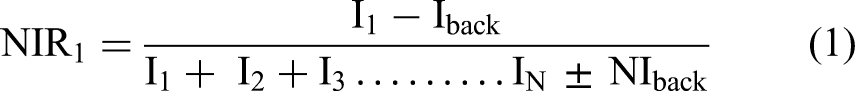
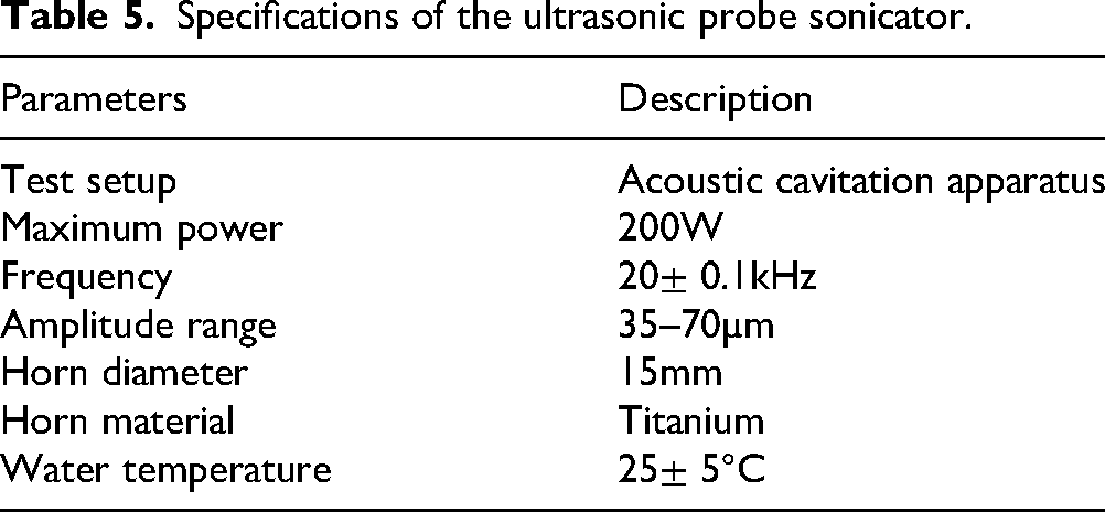
Cavitation erosion tests on the developed clads were performed in accordance with the modified ASTM G32-17 (indirect method) standard, using distilled water as the test medium. The cladded specimen was placed opposite the ultrasonic horn tip to ensure direct impingement of cavitation bubbles on the clad surface. The collapse of these bubbles generated localized impact forces, resulting in stress and subsequent material removal. Specimens measuring 15 × 15 mm2 in total thickness, with a clad layer of 5–5.5 mm, were utilized. Before testing, specimens were polished to a surface roughness of approximately 0.2 μm Rq, which is significantly below the ASTM G32-17 requirement of less than 0.8 μm. The polishing procedure followed the method described previously. Experiments were conducted using a probe sonicator-based ultrasonic setup (Kamtronics Technology, New Delhi, India; Model: Samkoon). Figure 4 presents a schematic of the indirect vibratory cavitation apparatus, and Table 5 provides detailed sonicator specifications. For cavitation testing, the optimized parameters were 0.5 mm SOD, 60 mm AMP, and 80 mm IMD. 36
Probe sonicator (a) experimental setup; (b) schematic diagram.
Specifications of the ultrasonic probe sonicator.
Results and discussion
Metallurgical properties
Figure 5(a) displays the BSE image of the transverse section of the microwave-processed NiCrSiC-5Mo composite clad. The deposited clad exhibits a uniform thickness of approximately 800 μm, derived from a 1 mm preplaced powder layer, and demonstrates a dense, crack-free structure that is well-bonded to the substrate. A distinct interface with a refined grain layer on both sides suggests partial dilution and strong metallurgical bonding between the clad and substrate. This planar refinement layer is attributed to the uniform heating and slow cooling characteristic of microwave cladding. The high-quality, defect-free clad supports the effectiveness of this process. The magnified view in Figure 5(b) reveals a uniform distribution of molybdenum particles within the nickel matrix, a feature commonly observed in Ni-based coatings, with only a few visible micropores. The porosity of the clad layer was measured at 0.97%, which is significantly lower than values typically reported for thermal-sprayed coatings and laser cladding. 54 This value is an average obtained from several SEM images, analyzed using image processing to ensure reliable results. The low level of pore formation is attributed to thermal imbalances during the solidification process. In addition, differences in thermal expansion between materials generate interfacial stresses, which can result in cracking or delamination. The microstructural observations suggest a relatively uniform distribution of phases and good metallurgical bonding at the interface, as inferred from SEM and EDS analysis.
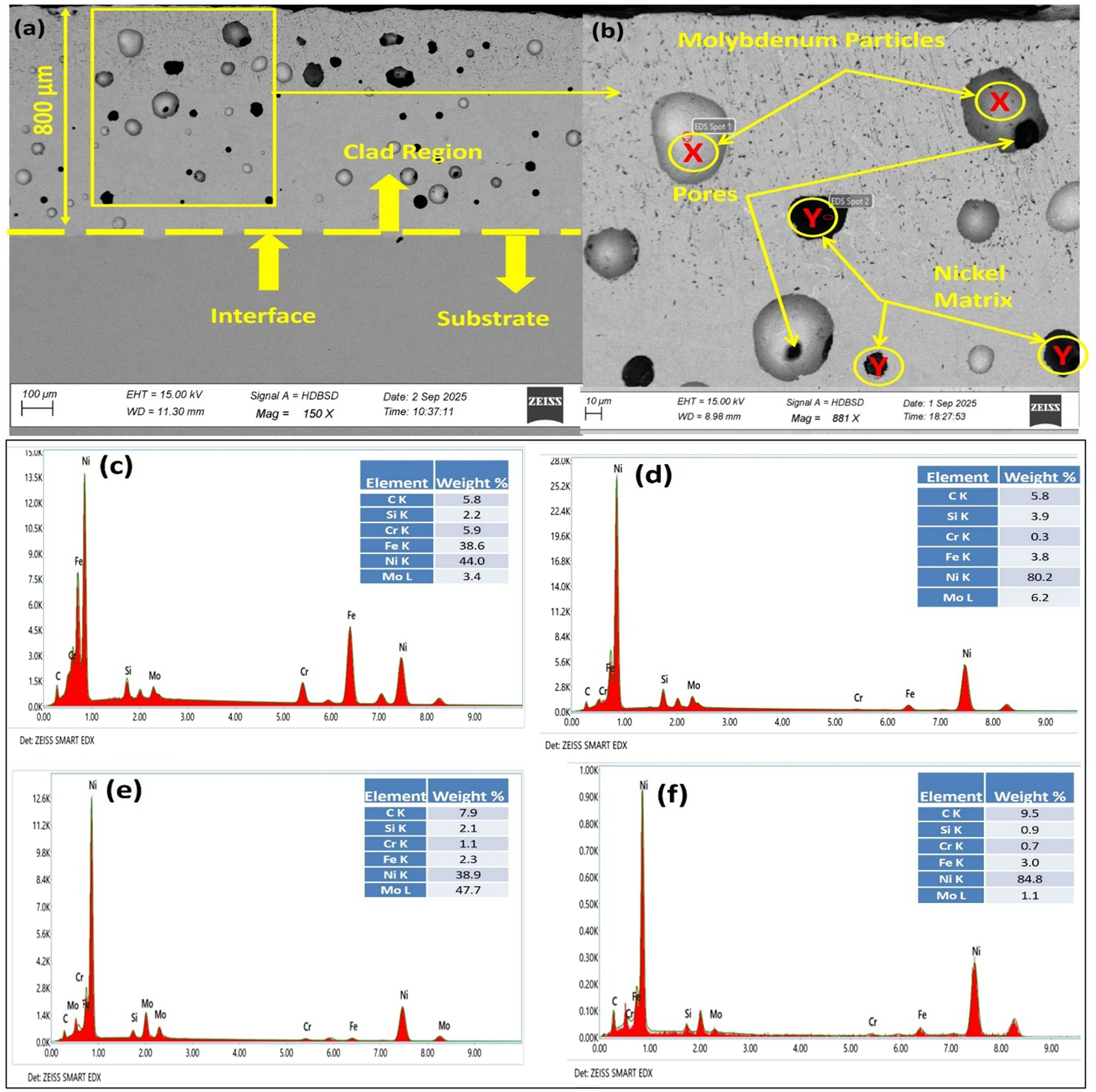
BSE images of NiCrSiC-5Mo composite clad: (a) transverse section; (b) magnified view of the clad section;(c) analysis of the transverse section using energy-dispersive spectroscopy; (d)EDS investigation of enlarged region; (e) EDS investigation of phase X;(f) EDS investigation of phase Y.
Microwave hybrid heating addresses this challenge by enabling volumetric and selective energy absorption, which ensures a more uniform and controlled temperature distribution. This approach minimizes thermal gradients, reduces the formation of residual stresses, and enhances the overall integrity of the clad–substrate interface. Energy-dispersive X-ray spectroscopy (EDS) analysis was conducted at four specific locations indicated in Figure 5 (a and b). Figure 5 (c–f) presents the EDS results for the transverse section, the enlarged region, phase X, and phase Y, respectively. The matrix region (location Y) exhibited a high concentration of nickel, with smaller amounts of Fe, Cr, Si, and C. In contrast, location X displayed a high molybdenum content and relatively low levels of Fe, Cr, and C. The detection of Fe in the clad region, despite its absence in the original powder composition, suggests partial dilution from the stainless-steel substrate. Figures 6(b–h) demonstrate a uniform distribution of Ni and Mo throughout the clad, confirming effective mixing and phase stability. Fe is primarily concentrated near the interface, indicating that substrate dilution is both limited and controlled. This elemental distribution supports strong interfacial bonding while maintaining the intended clad composition. As shown in Figures 5(c–f) and 6, EDS also confirmed the elemental composition of the white and black phases within the composite clad. The EDS findings were subsequently used to inform the interpretation of the X-ray diffraction (XRD) results.

EDS mapping of the NiCrSiC-5Mo composite clad: (a) mapped area, (b) elemental distribution overview, and individual maps of (c) C, (d) Si, (e) Mo, (f) Cr, (g) Fe, and (h) Ni.
X-ray diffraction analysis
The phase composition of the developed composite clads was analyzed using X-ray diffraction (XRD), and the major diffraction peaks were indexed with their corresponding crystallographic planes (hkl). Phase identification was carried out by matching the obtained patterns with standard ICDD database cards. The analysis revealed the presence of a Ni-based solid solution (γ-Ni) along with several intermetallic and oxide phases. During microwave processing, the clad powder was heated to its melting point and subsequently solidified upon cessation of microwave irradiation. This rapid heating and controlled cooling led to the formation of new crystalline phases. The XRD pattern of the microwave-processed NiCrSiC–5Mo composite clad is shown in Figure 7 and confirms the presence of γ-Ni (MoNi₄), intermetallic phases such as FeMo, MoSi₂, and Fe₇Mo₃, and an oxide phase, NiCr₂O₄. Among these, γ-Ni peaks were dominant, indicating that the Ni-based matrix forms the primary phase of the clad. The formation of intermetallic compounds such as MoNi₄ and MoSi₂ can be attributed to interactions between Ni, Mo, and Si during melting and solidification. The formation of Fe₇Mo₃ and FeMo suggests partial dilution from the SS-420 substrate, as iron was absent from the original clad powder. This observation confirms the existence of strong metallurgical bonding at the interface. The formation of these intermetallic phases is consistent with the Fe–Mo phase diagram, which indicates that Fe₇Mo₃ and FeMo are stable at elevated temperatures. During microwave processing, iron diffuses from the substrate while molybdenum migrates from the reinforcement, resulting in the formation of these intermetallic compounds under localized heating. During cladding, the Ni-based matrix undergoes complete melting, while the reinforcement particles experience partial dissolution and transformation. In particular, Mo tends to form Fe₇Mo₃ due to its favorable thermodynamic stability (lower Gibbs free energy). 52 The oxide phase NiCr₂O₄ forms during high-temperature processing under ambient conditions. Diffusion-driven reactions during microwave hybrid heating promote the formation of these phases. At elevated temperatures, elemental diffusion between the clad and substrate enhances interfacial bonding, while the presence of Mo and other elements contributes to the formation of hard, stable phases. These phases play a key role in improving the hardness and cavitation erosion resistance of the developed composite clads.
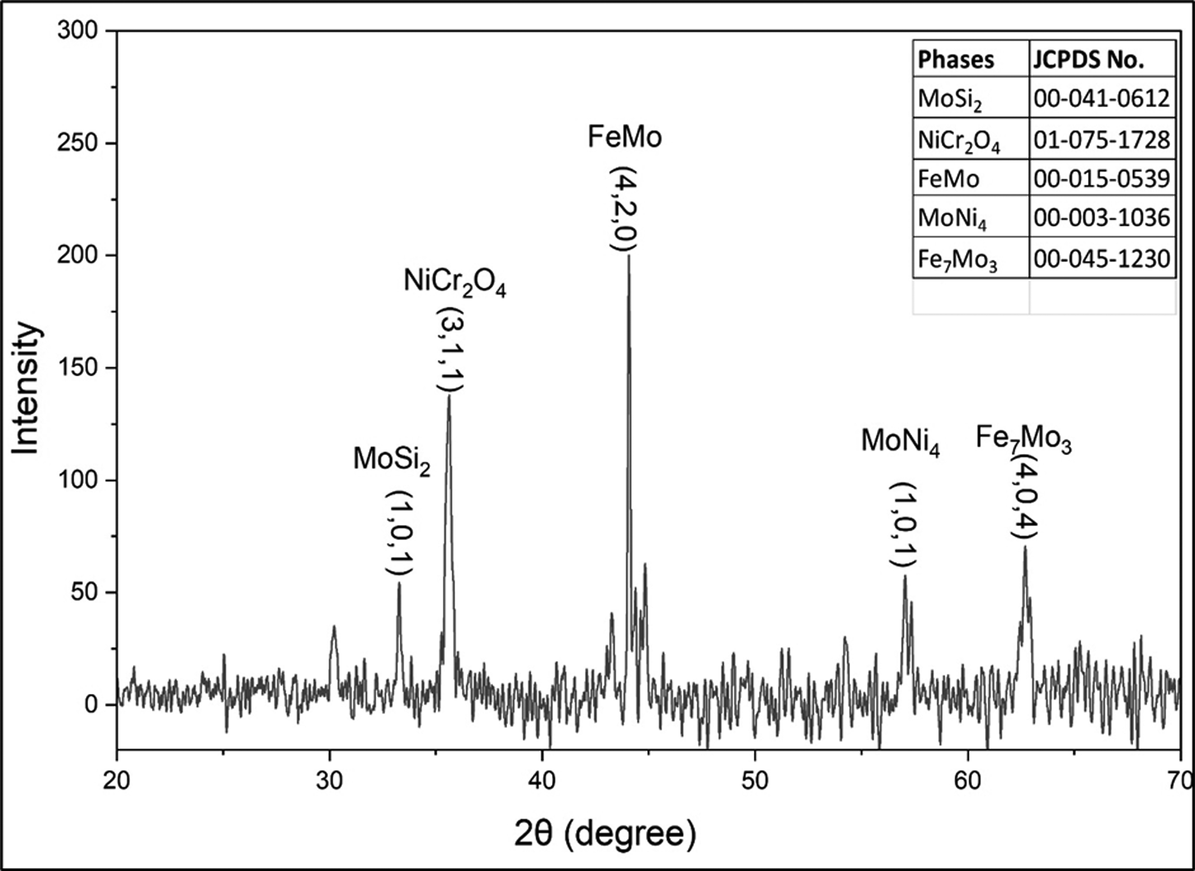
X-ray diffraction (XRD) patterns of the developed composite clads.
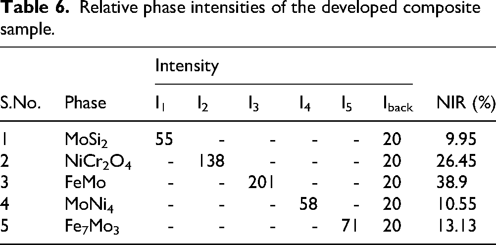
The XRD evaluation results (Table 6), based on normalized intensity ratio (NIR) values, show the phase distribution in the developed composite clad. Although NIR aids in comparing phase intensities, the values should not be interpreted as absolute quantities. The analysis reveals that FeMo (38.90%) is the primary phase, followed by NiCr₂O₄ (26.45%), Fe₇Mo₃ (13.13%), MoNi₄ (10.55%), and MoSi₂ (9.95%).
Relative phase intensities of the developed composite sample.
Mechanical properties
Simultaneous enhancement of both hardness and toughness significantly improves wear resistance in materials; however, achieving this balance within a single material system remains challenging. 37 In this study, composite clads were developed to address these performance requirements. Microhardness was measured at 80 μm intervals from the clad surface toward the substrate, with lateral measurements taken at the same spacing for both NiCrSiC-5Mo and NiCrSiC clads. The results demonstrated a uniform hardness profile in all directions, as shown in Figure 8(a–b), which confirms good microstructural consistency. The NiCrSiC-5Mo and NiCrSiC clads exhibited average hardness values of 591.53 ± 20 Hv and 473.25 ± 20 Hv, respectively, while the substrate measured 310 ± 20 Hv. Thus, the NiCrSiC-5Mo composite clad achieved nearly double the hardness of the base material. The reported hardness values are the average of five test samples. This increased hardness is a key contributor to improved wear resistance, primarily attributed to the formation of various oxide and intermetallic phases. Some variation in hardness values was observed because the indentations encompassed both the matrix and reinforcement regions.
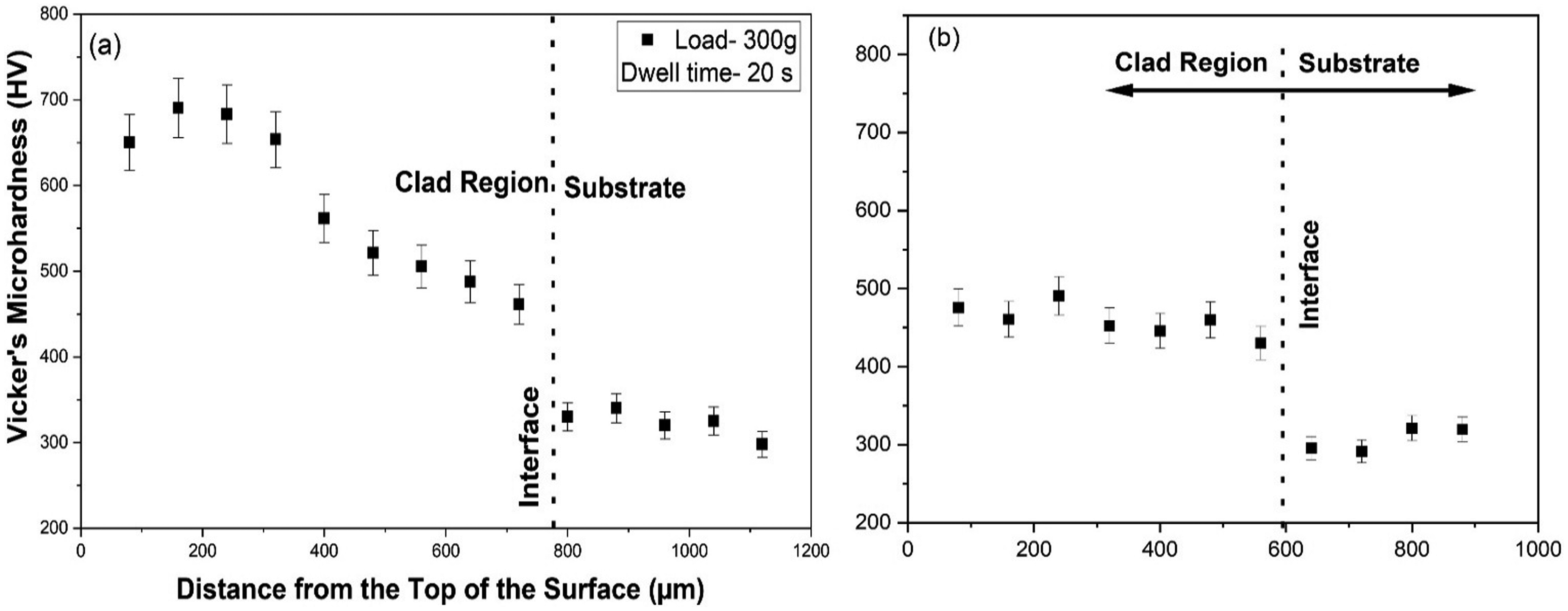
Microhardness distribution of the composite clad (a) NiCrSiC-5Mo and (b) niCrSiC.
Crystallite size
The addition of molybdenum facilitates heterogeneous nucleation by lowering the energy barrier at grain boundaries, which promotes crystallite structure refinement. This process produces finer grains and increased hardness. Analysis of the clad surface using Scherrer's equation (Equation 2) demonstrates a clear reduction in crystallite size with molybdenum addition, as presented in Table 7. These findings underscore the role of molybdenum in enhancing both the microstructure and mechanical properties of the cladding. Although Scherrer's equation provides a reasonable estimate, crystallite size measurements may be affected by factors such as instrumental broadening and peak overlap. The refinement mechanism is attributed to two primary effects: (1) reduced nucleation rates during microwave processing, which favor the formation of finer grains, and (2) increased dislocation density resulting from restricted crystallite growth.
18
Together, these effects account for the observed crystalline size. The inverse relationship between crystallite size and dislocation density is consistent with the Hall–Petch strengthening mechanism. As crystallite size decreases from approximately 51.49 nm in the unreinforced matrix to 33.526 nm in the composite clad, the resulting increase in grain boundary area directly contributes to the observed improvement in hardness (591.53 Hv). This nanoscale refinement, combined with the uniform distribution of hard molybdenum particles (Figure 5(a)), generates a synergistic strengthening effect. Grain boundary strengthening due to crystallite refinement and dispersion strengthening from ceramic reinforcement collectively result in nearly double the hardness of the base substrate.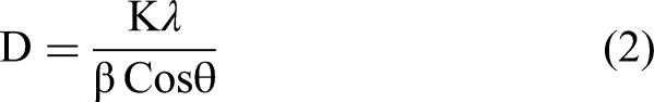
Calculation of crystallite size.
D is the crystallite size in nanometers. θ is the peak position in radians from the XRD pattern. The X-ray wavelength is 0.15406 nm. β is the full width at half maximum (FWHM) of the diffracted peak (in radians), and the Scherrer constant (K) is 0.9. These values are put into Scherrer's equation to estimate the average crystallite size from the broadening of XRD peaks.
Cavitation erosion investigation
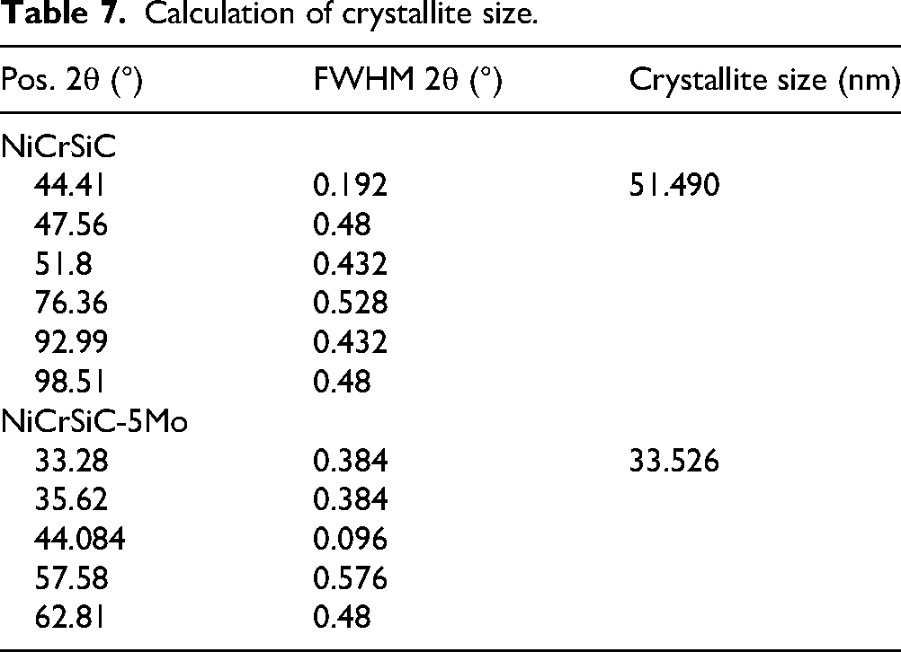
Cavitation erosion testing was performed on the SS-420 substrate and the microwave-processed NiCrSiC-5Mo and NiCrSiC composite clad, and the results are presented in Figure 9 as a function of time. All NiCrSiC-based clads performed better than the SS-420 substrate. Cavitation-induced weight loss steadily decreased as the reinforcement content increased. The NiCrSiC-5Mo clad showed the lowest weight loss. However, the percentage reduction in weight loss is shown in Table 8.
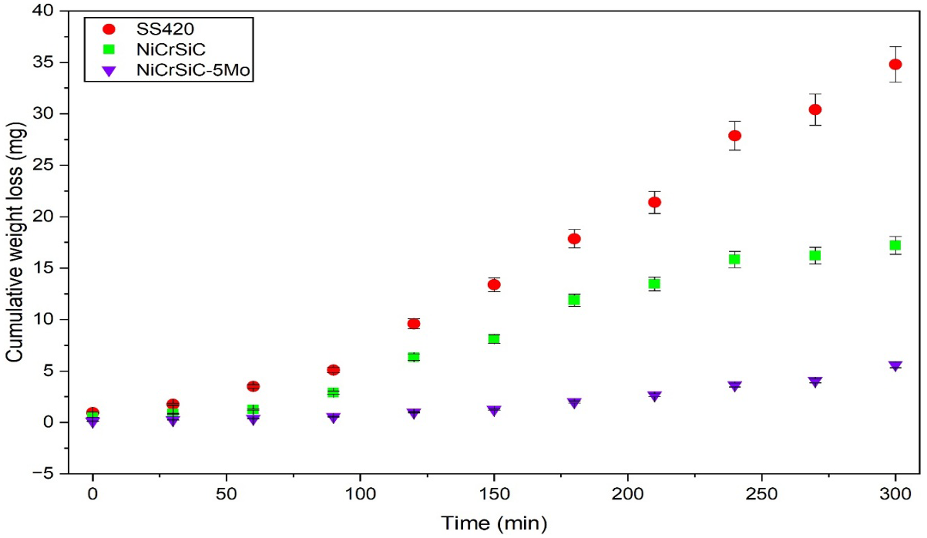
Cumulative weight loss over time for SS-420 and developed clads with 5% uncertainty.
Percentage variation in weight loss of the developed clads.
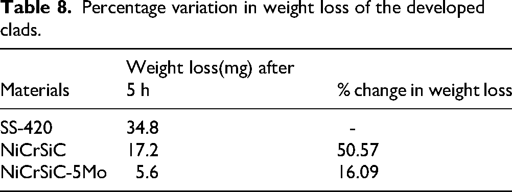
The increased weight loss observed in the pure NiCrSiC clad is attributed to the high stacking fault energy of Ni, which restricts work hardening during cavitation and accelerates material removal. Incorporating up to 5% Mo markedly reduces weight loss by enhancing both hardness and fracture toughness. Additionally, the Mo reinforcement interacts efficiently with microwave radiation, potentially enhancing atomic diffusion in SS-420, reducing stacking fault energy, and increasing the composite's resistance to cavitation erosion. The improvement in cavitation erosion resistance cannot be attributed solely to the increase in hardness and reduction in crystallite size. Although the hardness increased significantly, the enhanced performance is the result of a combined effect of microstructural refinement, formation of hard carbide and oxide phases FeMo, NiCr₂O₄, Fe₇Mo₃, MoNi₄, and MoSi₂, and improved interfacial bonding. The presence of these phases restricts plastic deformation and delays crack initiation under repeated bubble collapse. Therefore, cavitation resistance is governed by a synergy between hardness, phase composition, and microstructural stability rather than hardness alone. The MMC clads become harder because of the ceramic phases formed during microwave processing. This higher hardness strengthens the surface and slows down the start of pits and cracks. As the test continues, these ceramic phases also slow the merging of pits in the softer matrix. SS-420 has the lowest hardness, so it cannot stop early cracking or later crack growth, which leads to the highest weight loss. Even though adding more reinforcement increases hardness, the cavitation resistance does not improve much. This is likely because higher reinforcement levels also create more porosity. Stress concentrations at pore sites reduce material strength, designating these areas as primary initiation points for cavitation damage. While optimizing both hardness and toughness is critical for cavitation erosion resistance, an increase in hardness generally leads to decreased toughness. The primary objective of this study was to develop metal matrix composite (MMC) clads capable of protecting SS-420 from severe cavitation erosion. To achieve this, NiCrSiC-based clads reinforced with 5% Molybdenum (Mo) were fabricated. The pure NiCrSiC and NiCrSiC-5Mo clads demonstrated 2.02- and 6.21-times greater resistance, respectively, compared to SS-420 in terms of cumulative weight loss under identical testing conditions. The significant reduction observed for the reinforced clad indicates improved cavitation resistance; however, direct correlation with service life requires further investigation under real operating conditions. While the reduction in erosion rate suggests potential for extended service performance, quantitative life prediction would require integration of laboratory data with field conditions and component-specific loading scenarios.
Mechanism of cavitation-induced erosion
Figure 10 illustrates damage to the samples after 300 min of cavitation exposure. In Figure 10(a), the surface appears smooth and free of scratches before testing. Following erosion, the SS-420 specimen exhibits pits, craters, microcracks, and striations, as evident in Figure 10(b). Several brittle, protruding lips also emerge on the damaged surface. The primary degradation mechanisms identified are fatigue-controlled deformation and plastic deformation. Although localized brittle features were observed, no evidence of catastrophic spallation was detected within the test duration. The presence of a ductile Ni-based matrix alongside hard carbide and oxide phases helps in arresting crack propagation, thereby maintaining a balance between hardness and toughness. The eroded surfaces of the microwave-processed clads, as illustrated in Figure 10(c-d), exhibit cracks, pits, lip formation, and craters, which indicate the coexistence of brittle and ductile fracture modes. These observations confirm that surface damage results from high-impact loading caused by impingement jets generated during the collapse of vapor bubbles. The collapse of bubbles near the surface produces intense localized pressure, leading to plastic deformation. When the impact energy surpasses the mechanical strength of the material, surface fractures occur, resulting in pit formation. With continued exposure, repeated jet impacts further degrade these regions, causing pits to enlarge and develop into microcracks and craters. NiCrSiC-5Mo Clads exhibit minimal damage after 300 min of testing; only small pits and occasional craters are observed on the clad. This pattern indicates a transition from mixed fracture behavior to a predominantly brittle mode as reinforcement use.
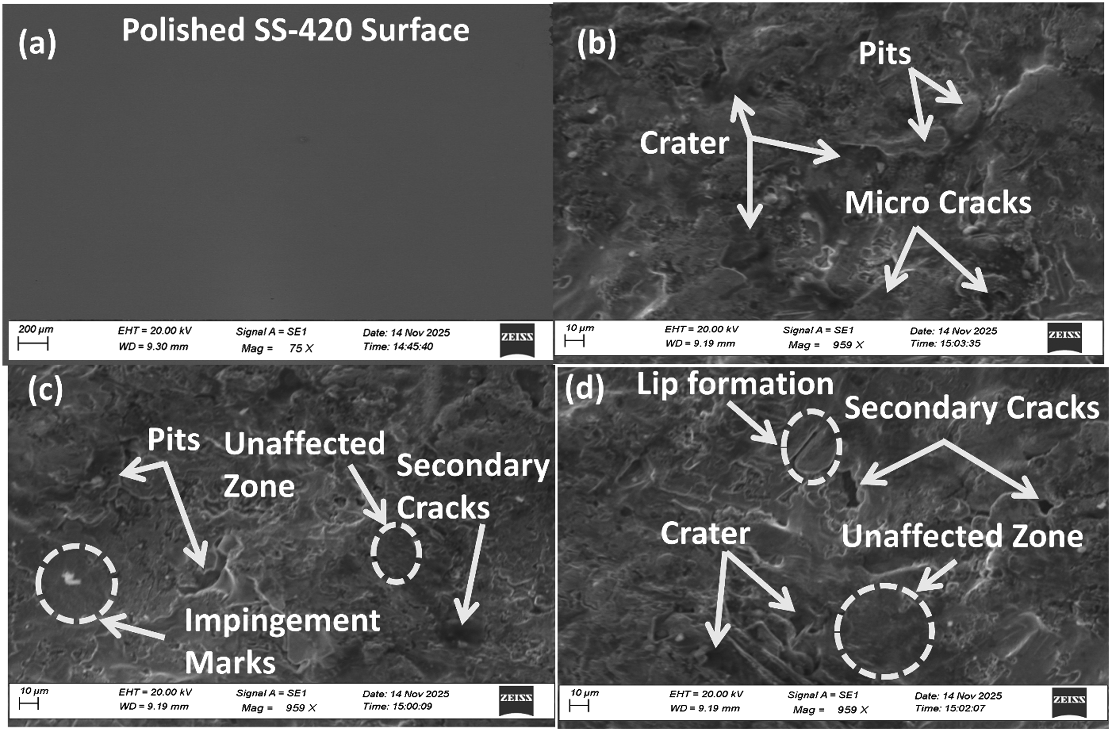
SEM images of the surfaces before cavitation erosion: (a) SS-420. SEM images after 300 min of cavitation erosion: (b) SS-420, (c) NiCrSiC clad, and (d) NiCrSiC-5Mo.
Additionally, the presence of impingement marks suggests that the impact energy from collapsing bubbles did not exceed the mechanical strength of these reinforced clads. Overall, all samples followed the same damage progression pathway, though the severity varied depending on reinforcement content.
Conclusion
The results presented in this study are specific to the SS-420 substrate. Variations in thermal expansion, dilution behavior, and phase interactions may influence the performance of the coating when applied to other materials such as bronze or duplex stainless steels. Therefore, caution should be exercised when extending these findings to different substrate systems, and further investigation is necessary. Cavitation erosion resistance typically increases with greater microhardness. However, this relationship is not strictly linear because microstructure and phase distribution also influence resistance to material loss. While cladding enhances hardness, excessive hardness may increase brittleness, resulting in crack formation and accelerated damage. Consequently, achieving an optimal balance between hardness and toughness is essential. The present results suggest that the developed composite achieves a favorable combination of these properties; however, further increases in hardness may not necessarily result in improved performance. The key outcomes of the present study are summarized below:
An 800 µm thick NiCrSiC-5Mo composite clad was fabricated on an SS-420 substrate using microwave cladding. The resulting clad exhibited high density (0.97% porosity), absence of interfacial or solidification cracks, and uniform distribution of oxide phases within the Ni matrix. Several intermetallic phases (FeMo, MoSi₂, Fe₇Mo₃, MoNi₄) and an oxide phase (NiCr₂O₄) were identified in the clad. The detection of Fe₇Mo₃ and FeMo, despite the absence of Fe in the initial clad powder, indicates partial dilution from the stainless-steel substrate and suggests strong metallurgical bonding at the interface. The dense and uniform structure of the clad resulted in significantly increased microhardness. Specifically, the clad demonstrated approximately twice the microhardness (591.53 ± 20 Hv) compared to the substrate (310 ± 20 Hv). In the absence of molybdenum cladding reinforcement, the microhardness was approximately 1.5 times higher (473.25 Hv) than that of the substrate. The reduction in crystallite size helped increase microhardness significantly. All cladded surfaces showed a major improvement in cavitation erosion resistance. The NiCrSiC-5Mo clad performed the best, providing about 6.21 times higher resistance than the SS-420 surface based on cumulative weight loss. Wear analysis showed that pits, craters, lip impingement marks, microcracks, and plastic deformation were the main damage features. With the addition of reinforcement, the failure gradually shifted from a ductile mode to a more brittle type of damage.
Limitation and future work
Direct measurement of temperature during microwave processing was not feasible due to equipment limitations. Future research could employ infrared thermography or fiber-optic sensors to record real-time temperature and provide a more comprehensive understanding of heat distribution during cladding. While ASTM G32 cavitation tests provide controlled and repeatable conditions, real service environments involve complex interactions such as flow-induced stresses, pressure fluctuations, and corrosion effects, which may influence erosion mechanisms and material performance. Therefore, further studies under simulated or actual service conditions are required for comprehensive evaluation.
Footnotes
Acknowledgment
I would like to acknowledge the support provided by the external laboratories that contributed to this work. I am grateful to IIT Delhi for facilitating the microstructure and mechanical characterization, and to TIET Patiala for providing access to their cavitation testing facility. Their assistance and technical support were essential to completing this study.
Author contribution(s)
Funding
The authors received no financial support for the research, authorship, and/or publication of this article.
Declaration of conflicting interests
The authors declared no potential conflicts of interest with respect to the research, authorship, and/or publication of this article.