
Abstract
Laser cladding technology presents a promising method for fabricating multi-principal element alloy (MPEA) coatings, yet cracks remain one of the most prevalent defects in HEA laser cladding. In this study, FeCr0.5NiCu0.5 multi-principal element alloy coatings were produced on heat-resistant steel (12Cr1MoV) using laser cladding with varying scanning speeds. The study systematically examined the types and mechanisms of cracks within the multi-principal element alloy coatings and also summarized the effects of scanning speed on the coating's dilution rate and cooling rate. Results indicate that an increase in scanning speed significantly elevates the coating's dilution rate and the risk of cracking. With the increase in scanning speed, the cooling rate has risen from 2.68 × 10³ K/s to 3.7 × 10⁴ K/s, achieving an order of magnitude improvement. The secondary dendrite arm spacing (SDAS) has diminished from 4.02 µm to 1.8 µm, resulting in a significant refinement of the grains. Cracks within the coating are categorized into macrocracks and microcracks. Macrocracks originate at the interface between the coating and the substrate, induced by the substantial thermal expansion coefficient mismatch between the multi-principal element alloy and heat-resistant steel. Microcracks manifest as intergranular cracks due to the distribution of low-melting-point Cu elements along the grain boundaries, which increases the brittleness of the boundaries.
Introduction
Traditional alloy design typically involves the selection of one or two elements as the primary constituents. However, with the relentless advancement of technology, such conventional alloys have constrained the advancement of materials, thereby limiting the further development of their structures and properties. The current industry urgently necessitates the development of novel alloys to fulfill its evolving demands. In 2004, Yeh introduced a groundbreaking alloy design concept known as High-Entropy Alloys (HEAs) or Multi-principal Element Alloy (MPEA). 1 Typically composed of five or more elements, HEAs are recognized by their configurational entropy, which typically exceeds 1.5R at room temperature (according to the Boltzmann equation). 2 Compared to traditional alloys, HEAs exhibit a higher mixing entropy and demonstrate four primary effects: the slow diffusion effect, 3 the high-entropy effect, 4 the lattice distortion effect,5,6 and the cocktail effect. These characteristics, when combined with appropriate composition design and microstructure control, can endow specific HEA systems with desirable properties such as corrosion resistance, high-temperature stability, and mechanical performance. Due to their unique microstructure and superior performance, HEAs exhibit promising applications in domains such as aerospace, high-speed rail, and renewable energy. 7 Currently, a variety of methods are available for the fabrication of HEAs, including plasma cladding, laser cladding, powder metallurgy, and vacuum melting.
Laser cladding (LC) technology employs a high-energy laser beam as a heat source, thereby forming a robust metallurgical bond coating by simultaneously melting the powder and the substrate. As an advanced manufacturing technique, it has garnered significant attention.8,9 Compared to traditional surface treatment methods, LC offers advantages including high metallurgical bond strength, minimal substrate impact, low dilution rates, and operational simplicity. It has found extensive applications across aerospace, automotive, nuclear power, and chemical industries. Consequently, the use of LC to fabricate multi-principal element alloys has become a predominant research focus in recent years, offering the potential to produce coatings of superior quality for modern industry through laser cladding. 10
However, due to the rapid cooling and heating characteristics of laser cladding, significant residual stresses are generated within the coating, resulting in a tendency for cracking. The presence of cracks, defects, and porosities in the coating renders it susceptible to the complex physical, chemical, and metallurgical processes associated with LC, including the transmission and absorption of laser energy, the rapid melting and bonding of powder and substrate, and the evolution of the microstructure during solidification. These imperfections compromise the mechanical properties and service life of the coating, thereby limiting the applicability of LC. 11 Lyu et al. 12 discovered that cracks can significantly reduce the corrosion resistance of CrFeCoNiMo0.2 high-entropy alloys (HEAs) treated with high-current pulsed electron beam (HCPEB). Our previous research also indicated that cracks diminished the high-temperature corrosion resistance of laser-clad FeCrAl coatings. 13 Currently, an established strategy involves optimizing LC process parameters to minimize defects and improve coating quality. For instance, Marchese et al. 14 investigated the impact of process parameters on FeCrNi alloys and found that the optimization of these parameters could effectively reduce porosity and crack formation.
In recent years, numerous scholars have conducted extensive research on the causes and control methods of cracking in LC coatings. Fu et al. 15 discovered that in the Ni60A coating, a decrease in scan speed corresponded with a gradual reduction in the cracking rate of the coating; a lower scanning speed facilitates the attainment of a crack-free coating. Jian et al. 16 investigated the impact of laser power on the coating cracking rate, revealing that the propensity for cracking in the coating increases incrementally as laser power is augmented. Zhang et al. 17 undertook an investigation into Al-Cu-Mg alloys, wherein it was ascertained that Cu and Mg exhibit a heightened susceptibility to crack formation. A slower scanning velocity was found to mitigate the incidence of these cracks. Ding et al. 18 preheated the Q460E substrate of the 12CrNi2 coating at different temperatures, finding that preheating effectively reduced residual stress in the coating, thereby diminishing defects. Ramakrishnan et al. 19 discovered that cracking in Inconel 738 coatings is attributed to the microsegregation of Al and Ti elements and low-melting-point crack boundaries. Yu et al. 20 explored the optimization of laser cladding parameters, which significantly reduced cracks and porosity in YCF101 alloy coatings. In summary, current research primarily focuses on defects in traditional alloys, whereas studies on laser-cladded multi-principal element alloys have predominantly concentrated on the effects of element ratios, heat treatment processes, and processing parameters on coating microstructure, mechanical properties, and corrosion resistance.21–23 Therefore, a more in-depth investigation into crack defects in heat-resistant steel laser-cladded multi-principal element alloy coatings is essential.
In this paper, laser cladding technology was employed to fabricate FeCr0.5NiCu0.5 MPEA coatings on heat-resistant steel (12Cr1MoV). To ensure the presence of cracks in the coatings, five different scanning speed processes were designed for the preparation. The phase structure of the coatings was analyzed using X-ray diffraction (XRD), while optical microscopy (OM), scanning electron microscopy (SEM), and the accompanying energy dispersive spectroscopy (EDS) were utilized to characterize and observe the cracks in the MPEA coatings, analyzing the types and mechanisms of the cracks. The research findings provide a reference for the development of high-quality, crack-free multi-principal element alloy coatings.
Experimental
Materials and coatings manufacturing methods
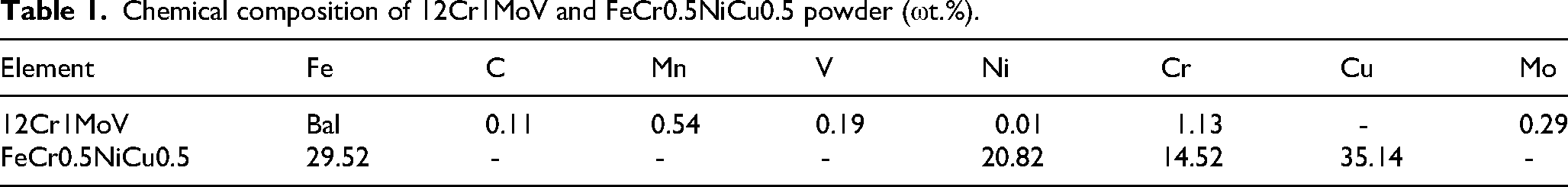
In this study, the powders selected for the laser cladding experiments are FeCr0.5NiCu0.5 MPEA powders produced via vacuum atomization, with a purity exceeding 99.8% and a particle size ranging from 15 to 53 μm, as illustrated in Figures 1(a) and (b). The substrate material selected is heat-resistant steel (12Cr1MoV), with dimensions of 150 mm × 50 mm × 5 mm; specific dimensions and the microstructure are presented in Figure 2(a). The microstructure of the substrate material 12Cr1MoV, as shown in Figures 2(b) and (c), is predominantly composed of ferrite, with a minor presence of pearlite. The chemical composition of both the heat-resistant steel substrate and the FeCr0.5NiCu0.5 MPEA powders is detailed in Table 1. Based on the composition listed in Table 1, the configurational entropy of the FeCr0.5NiCu0.5 coating is calculated to be 1.35R, which lies below the 1.5R threshold. Strictly speaking, this coating should therefore be classified as a medium-entropy alloy (MEA) coating. Nonetheless, it retains the characteristics of a multi-principal element alloy, and is accordingly designated as a multi-principal element coating in this study.
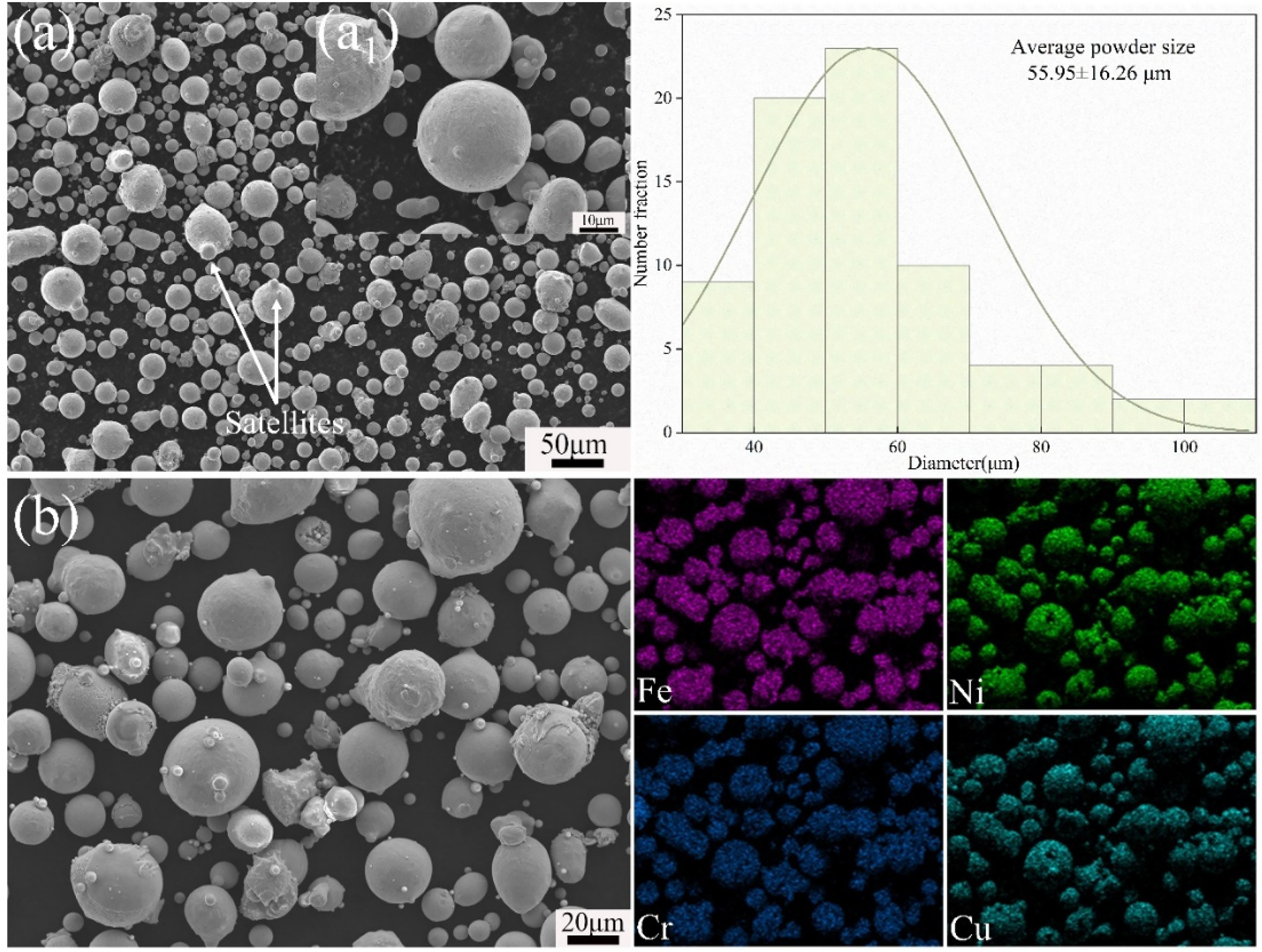
Multi-principal element alloy powders and classification.
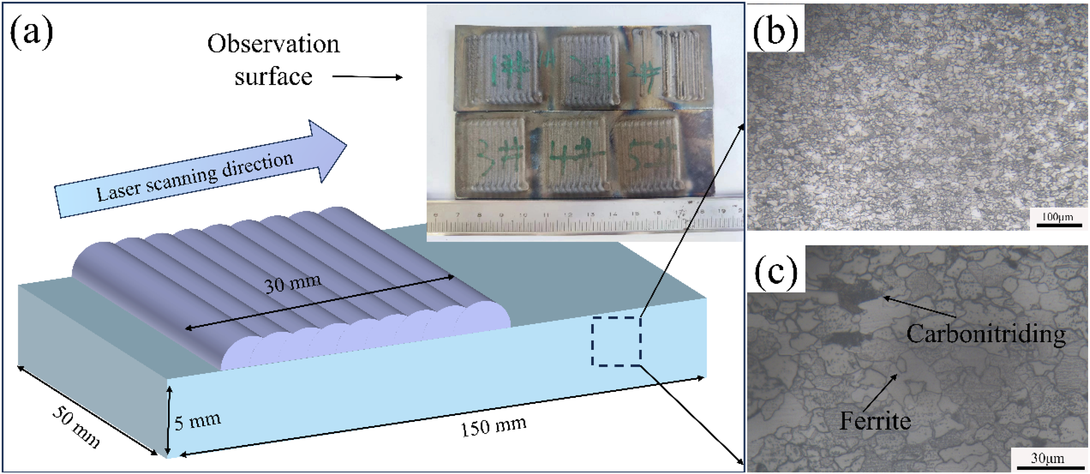
Dimensions and microstructure of heat-resistant steel plates.
Chemical composition of 12Cr1MoV and FeCr0.5NiCu0.5 powder (ωt.%).
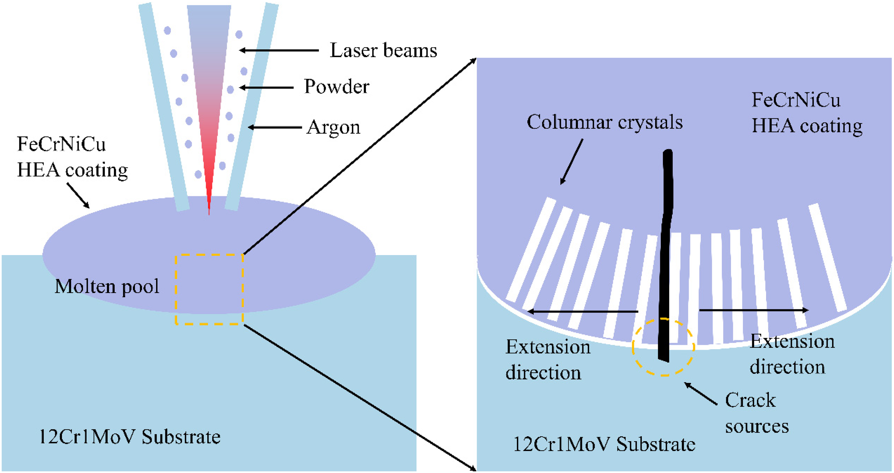
The laser cladding experiment utilized the ZKZM-2500 high-speed laser cladding system. The laser employed was a fiber laser with a maximum power of 2.5 kW and an adjustable minimum of 25 W. The laser spot diameter was 3 mm, the wavelength was 1080 nm, and the defocus distance was 15 mm. Powder feeding was conducted via a three-axis synchronous feed system. Prior to coating preparation, the substrate was subjected to surface sandblasting to remove impurities and grease, followed by washing with alcohol and drying. For this experiment, the laser power was set to 2 kW, with a powder feed rate of 12 g/min,overlap ratio of 50%,and scanning speeds of 22 mm/s, 33 mm/s, 44 mm/s, 55 mm/s, and 66 mm/s. The samples were sequentially labeled as S1, S2, S3, S4, and S5. During the coating process, argon was used both as the powder carrier gas and as a protective gas, with a flow rate of 2.5 L/min for the powder carrier gas and 5 L/min for the protective gas. After the coating is completed, the specimen is cut into dimensions of 17 mm × 5 mm utilizing wire cutting technology for microstructural characterization. A simplified schematic of the coating preparation is depicted in Figure 2(a).
Microstructural characterization
The samples designated for microstructural characterization were sequentially polished using 400, 600, 800, and 1000 grit sandpapers, followed by diamond suspension polishing. They were then etched using aqua regia (HCl: HNO3 = 1:3) solution, rinsed with alcohol, and air-dried. X-ray diffraction (XRD, DX-2700) analysis was conducted using a copper target operating at 40 kV and 40 mA, with a 2θ range of 20°–100° and a scanning speed of 3°/min. An optical microscope (GX71) was employed to observe the metallographic structure of the samples, while a JSM-7800F scanning electron microscope, with an attached energy dispersive spectrometer (EDS), was used to analyze the microstructure and elemental distribution of the samples. The operating voltage was maintained at 15 kV, with a current of 8 mA and an approximate working distance of 10 mm. The secondary dendrite arm spacing (SDAS) was measured at the top region of the coatings using high-magnification SEM images. For each sample, at least 5 different fields of view were captured. In each field, a minimum of 10 well-defined secondary dendrite arms were selected along a line parallel to the primary dendrite growth direction. The SDAS was determined by dividing the measured total length by the number of dendrite arms intercepted, using the linear intercept method. The average value from all fields was reported as the SDAS for that sample, with the standard deviation indicating the measurement uncertainty.
Results
Coatings’ morphology
Figure 3 depicts the cross-sections of five different MPEA coatings at various scan speeds, accompanied by a straightforward parameterization of the coatings (coating height h, coating depth b, coating width w). It is evident that the coatings and substrate can be clearly distinguished. First, except for the S1 coating, all FeCr0.5NiCu0.5 MPEA coatings exhibit prominent cracks, predominantly perpendicular to the substrate, appearing as longitudinal fissures. Furthermore, these cracks proliferate into the substrate as the scan speed elevates, culminating in the S5 coating, where the fissures permeate the substrate and compromise its integrity. In addition, the FeCr0.5NiCu0.5 MPEA coating formed by laser cladding has a good metallurgical bond with the substrate, and no pores were found between the coating and the substrate. This can be demonstrated by the additional scanning electron microscope images as shown in Figure 4.
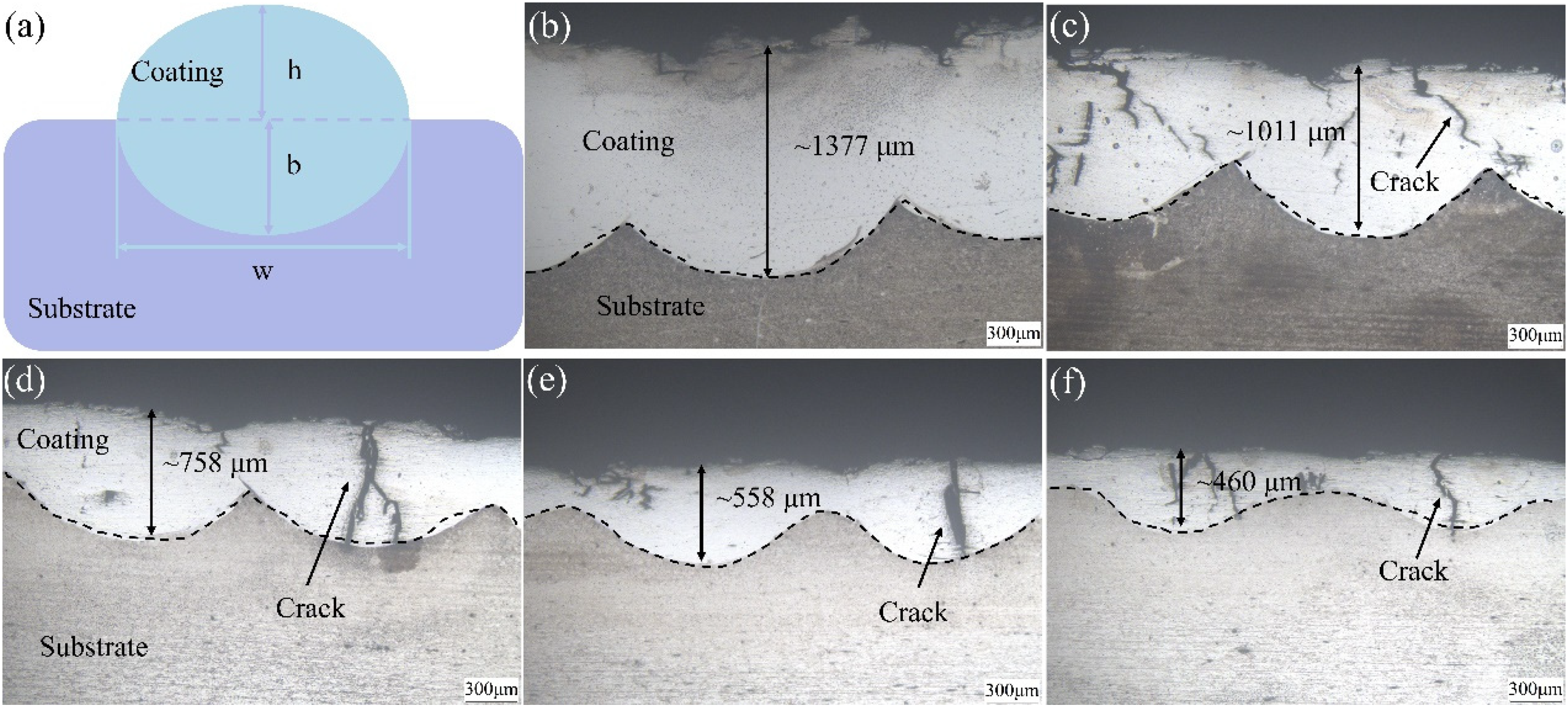
Cross-sectional morphology of FeCr0.5NiCu0.5 MPEAs coatings;(a) schematic diagram of the coating; (b)S1; (c)S2; (d)S3; (e)S4; (f)S5.
EDS spectrum of FeCr0.5NiCu0.5 multi-principal element alloy coating (a) S1, (b) S2, (c) S3, (d) S4, (e) S5.
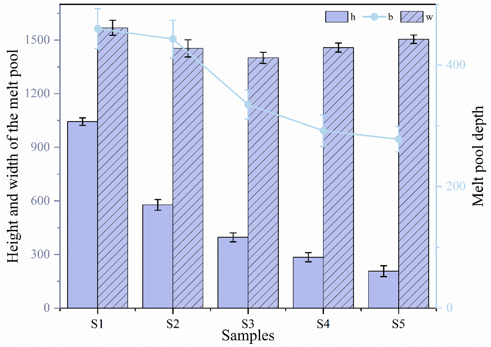
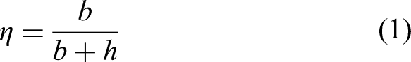
Figure 5 shows the height, depth, and width of the melt pool at different scanning speeds. As the scanning speed increases, the height and depth of the melt pool decrease, while the width first decreases and then increases. From Figure 6, it can be seen that as the scanning speed increases, the coating thickness gradually decreases, and the dilution rate gradually increases. The dilution rate is calculated as:
24
Parameters of melt pool fusion at different scanning speeds.
Coatings thickness and dilution rate.
In the equation, η represents the dilution rate, b denotes the height of the molten pool, and h signifies the depth of the molten pool.
By adjusting the scanning speed, the coating thickness ranges from 1377 μm (S1) to 460 μm (S5), with a dilution rate of 24.1% (S1) to 62.1% (S5). The dilution rate of the coating refers to the change in coating composition resulting from the simultaneous melting of powder and substrate in the laser cladding process. This is influenced by differences in density and liquid surface tension between the powder and the substrate, which facilitates the convective transport of substrate elements into the coating. 25 When the dilution rate is too low, the bond between the coating and substrate is weak, resulting in poor metallurgical adhesion and potential coating detachment. Conversely, an excessively high dilution rate alters the composition of the coating, leading to uncertainties in coating quality, a higher propensity for cracking and deformation, and a reduction in coating performance. As illustrated in Figure 6, when the scanning speed is set to 66 mm/s, the coating dilution rate reaches up to 62.1%. This increase can be attributed to the elevated scanning speed, which significantly reduces the coating thickness while slightly decreasing the melt pool depth, thereby enlarging the element exchange area at the melt pool's bottom. On the other hand, since this experiment involves continuous coating rather than a single pass, at an overlap rate of 50%, the repeated scanning of the melt pool enlarges its area.
Phase structure analyse
High-entropy alloys typically consist of five or more principal elements, each with varying atomic interactions. Parameters such as crystal structure, atomic size difference (d), and valence electron concentration (VEC) can be utilized to assess whether a stable solid solution can form within the alloy.26,27 Additionally, the combined parameter of atomic radius differences (
The calculated results are presented in Table 2. Generally, when Ω > 1.1 and δ < 6.6%,
28
the FeCr0.5NiCu0.5 multi-principal element alloy tends to form a simple solid solution. Additionally, the valence electron concentration (VEC) of the multi-principal element alloy is computed to be 8.333. The formula is as follows: (VEC)i represents the valence electrons of individual elements. When the alloy's VEC ≧ 8, it is prone to forming a stable FCC phase,
29
and the computed results align with the XRD detection findings.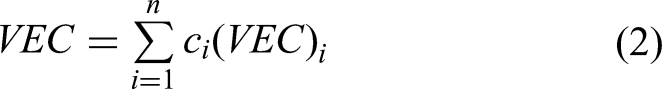
Parameters of FeCr0.5NiCu0.5 multi-principal element alloy.

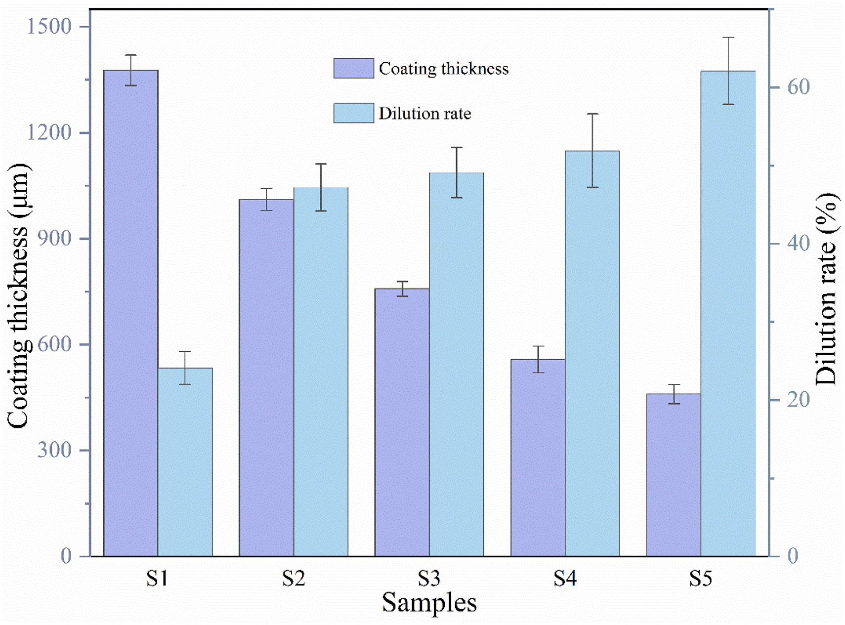
The phase structure of FeCr0.5NiCu0.5 powder and the laser cladding samples is illustrated in Figure 7(a). Both exhibit a single FCC phase, consistent with the aforementioned calculated structures. It was also observed that the laser cladding process does not alter the FCC phase of the powder, and variations in scanning speed have no impact on the phase structure of the samples. Compared to the diffraction peak positions of the powder, the (111) diffraction peak of the coating shifts slightly to the right, indicating a decrease in the (111) interplanar spacing according to Bragg's equation 2d sin θ = nλ. Although the scanning speed has changed, the diffraction peaks of the coating have not moved significantly. Such a minor shift may fall within the range of normal measurements or composition variations, indicating that the laser cladding scanning speed has a very small impact on the lattice parameters.

XRD spectra of FeCr0.5NiCu0.5 powder and coatings at various scanning rates.
Microstructure analysis
Figure 4 presents the EDS spectrum of the coating at different scanning speeds. From Figure 4, it is evident that the scanning speed does not affect the uniformity of the coating composition, with a clear distinction between the coating and the substrate. Due to the characteristics of laser cladding, a high-energy laser source instantaneously forms a melt pool upon interacting with the powder and substrate. Under the influence of Marangoni convection, elements from the coating can be detected in small amounts within the substrate. The primary elements of the coating—Fe, Cr, Ni, and Cu—are evenly distributed, with no evidence of enrichment near cracks.
Figure 8 illustrates the cross-sectional microstructure of FeCr0.5NiCu0.5 multi-principal element alloy coatings at various scanning speeds (S1-S5), with the deepest part of the molten pool as the axis. The microstructure of the coating is observed at the bottom, middle, and top. It is evident from the figure that the coating primarily comprises dendrites and a minor amount of equiaxed crystals, with changes in scanning speed having minimal impact on the microstructural characteristics of the coating. As illustrated in Figure 8a1-e1, a metallurgical bond is evident between the multi-principal element alloy coating and the heat-resistant steel substrate, ensuring the coating's reliable performance in any environment. With increasing scan speed, the bond between the coating and substrate remains unchanged. In the bottom images of the sample (Figure 8a1-e1), orented columnar crystals are observed growing perpendicular to the coating-substrate interface. In the middle images of the sample (Figure 8a2-e2), the columnar crystals gradually evolve into dendrites or fine equiaxed grains with certain preferred orientations. During the laser cladding process, the heat generated by the laser is transferred from the melt pool to the substrate and dissipates, with the thermal flow being perpendicular to the coating-substrate interface. Consequently, the grains grow in the direction of the heat dissipation. On the surface of the coating, a pronounced dendritic structure is evident, as illustrated in Figure 8a3-e3. The grain structure primarily results from the cooling rate E = G × R,30–32 where G represents the temperature gradient and R denotes the solidification rate, along with the parameter G/R. The term G × R determines the size of the coating structure, while G/R influences its morphology. A higher cooling rate (G × R) tends to refine the grains, with a higher G/R generally favoring the formation of planar crystals, whereas a lower G/R is more likely to produce equiaxed crystals. 33

Microscopic morphology of FeCr0.5NiCu0.5 multi-principal element alloy coating cross-section: (a) S1, (b) S2, (c) S3, (d) S4, (e) S5.
At the interface between the coating and the substrate, a higher G/R ratio results in the formation of a planar crystal layer, which subsequently transitions into columnar crystals. As the G/R ratio increases, the central region of the coating evolves from columnar crystals to equiaxed dendrites or coarse dendrites. Notably, while the top of the coating generally exhibits a lower G/R ratio, favoring the formation of equiaxed dendrites, the sample in question displayed coarse dendrites instead. This apparent discrepancy can be explained by considering multiple factors. First, although the cooling rate (G × R) is highest at the top (Figure 9), leading to reduced SDAS, the absolute scale of the dendrites is also influenced by the local solidification time. At the top, solidification occurs last, and the dendrites have more time to develop and coarsen compared to regions that solidify earlier. Secondly, as solidification proceeds, solute elements, particularly Cu, are rejected from the solid and accumulate in the remaining liquid. This solute enrichment at the top enhances constitutional supercooling, which can promote dendritic growth and potentially coarsen the structure through mechanisms such as dendrite arm remelting and coalescence. The observed Cu segregation at grain boundaries (Figure 10) supports the occurrence of significant solute redistribution. Marangoni convection in the melt pool can locally alter thermal and solutal conditions, potentially modifying the solidification morphology at the free surface. Therefore, the coarse dendritic morphology at the top does not contradict the G/R-based predictions but rather reflects the complex interplay of thermal, solutal, and fluid flow effects during the final stages of solidification. The observed decrease in SDAS with increasing scanning speed (Figure 9) remains consistent with the cooling rate-controlled refinement of the dendritic structure. Additionally, the dendritic structure at the top of the coating is distinctly pronounced, and the secondary dendrite arm spacing (SDAS) of the top region was measured. The cooling rate at the coating's top was calculated using SDAS (Formula 3).34,35
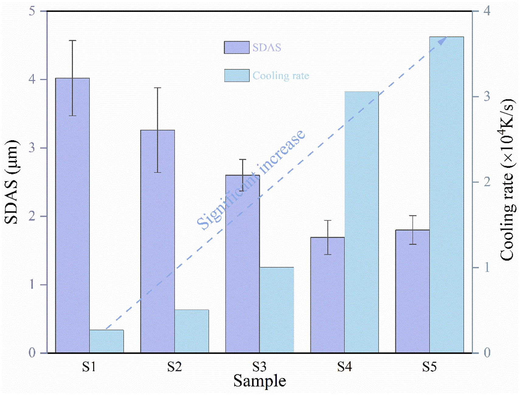
SDAS of different scanning speeds coatings and calculated cooling rates.
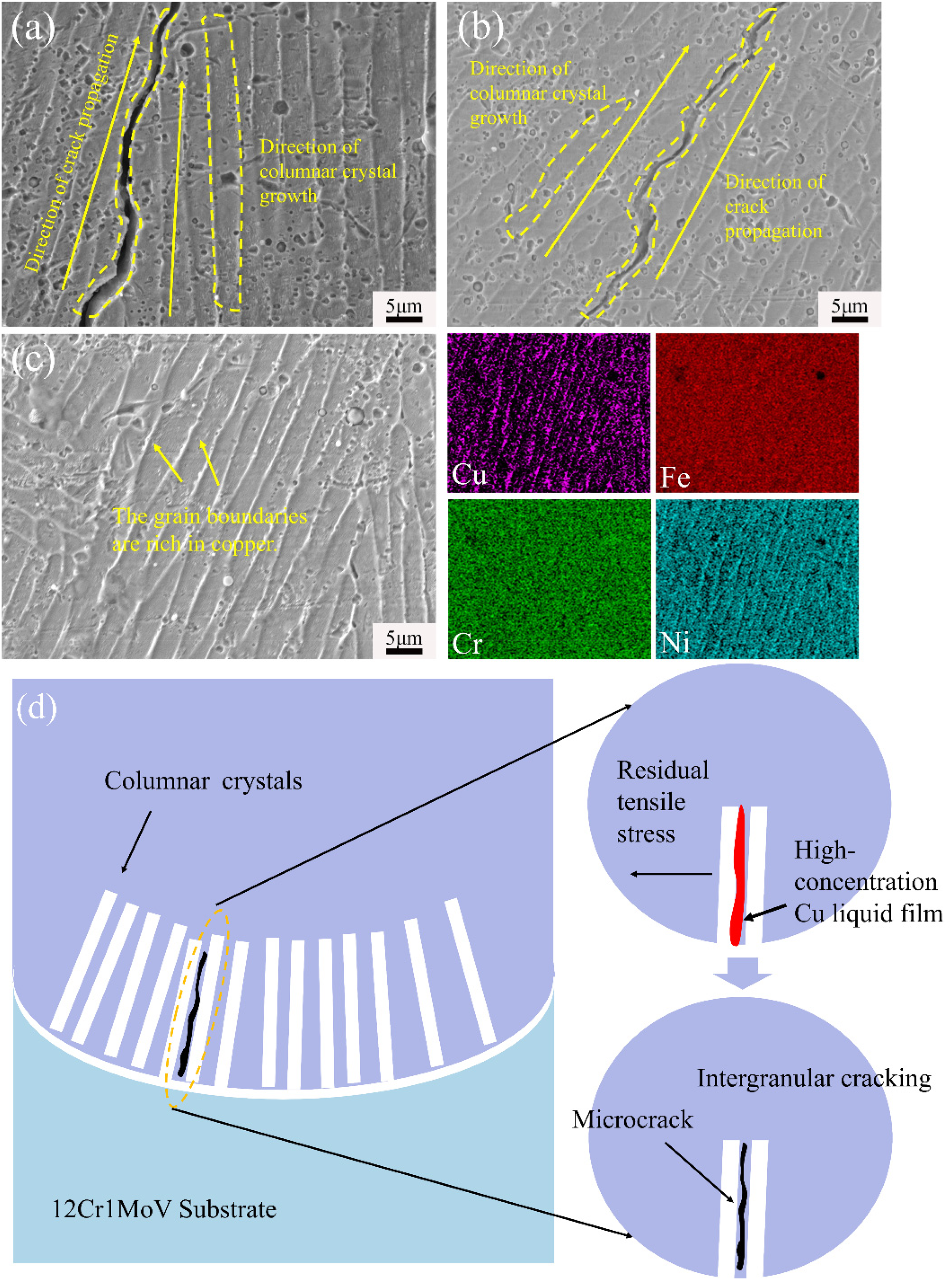
SEM morphology of microcracks (a) S2, (b)and(c) S5, (d) schematic diagram of microcrack mechanisms.
D represents the SDAS (μm), E denotes the cooling rate (K·s⁻1), while α and β are 54.38 and 0.33, respectively. 35 As illustrated in Figure 9, with an increase in scanning speed, the SDAS at the top of the coating exhibits a downward trend. At a scanning speed of 66 mm/s, the SDAS in the top region of the coating decreases to 1.8 μm, and this statistical result aligns perfectly with the observed data. It is well-established that the grain size of the material depends on the cooling rate and temperature gradient. By examining the SDAS of the coating, a rough estimation of the cooling rate during the laser cladding process can be derived. Figure 9 displays the cooling rates for the top regions of five coatings. The cooling rate generally shows a positive correlation with the scanning speed; moreover, even a slight increase in scanning speed significantly enhances the cooling rate, with the top cooling rate of S5 reaching 3.7 × 10⁴ K/s, an order of magnitude higher than that of S1. Therefore, the increase in cooling rate significantly contributes to the refinement of the grain structure in multi-principal element alloy coatings.
Discussion
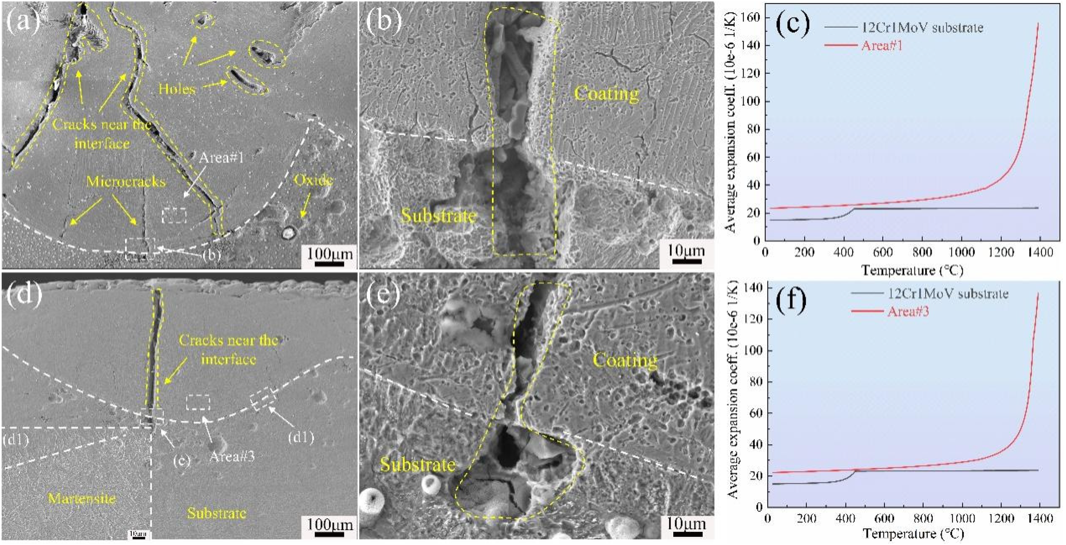
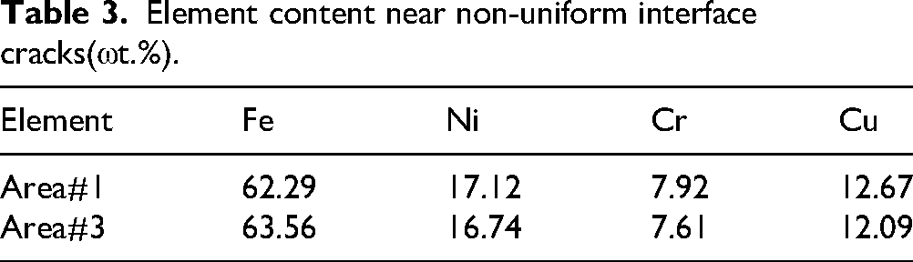
Figure 11 illustrates the scanning electron microscope morphology of cracks near the non-uniform interface between the FeCr0.5NiCu0.5 multi-principal element alloy coating and the 12Cr1MoV heat-resistant steel substrate in samples S2 and S5, which were subjected to laser cladding. As observed in Figures 11(a) and (b), the cracks originate from the interface where the coating adheres to the substrate. Additionally, EDS point element analysis was conducted near the non-uniform interface, as detailed in Table 3. The collected elemental information was utilized to calculate the thermal and physical properties of the material using JMatPro software based on the CALPHAD method.
36
The thermal expansion coefficients of materials near the non-uniform interface cracks in Figure 11(c) and (f), as well as the 12Cr1MoV heat-resistant steel matrix material, exhibit variation. It is noteworthy that the thermal expansion coefficient in the region adjacent to the interface cracks has changed due to variations in scanning speed and differing diffusion intensities and elemental compositions between the matrix and the coating. As illustrated in Figures 11(c) and (f), the thermal expansion coefficient of the material near the interface cracks is greater than that of the matrix. The significant disparity in thermal expansion coefficients between the coating material and the matrix results in the accumulation of substantial thermal stresses during the laser cladding process, leading to the formation of cracks at the interface junction.
37
The equation for thermal stress is: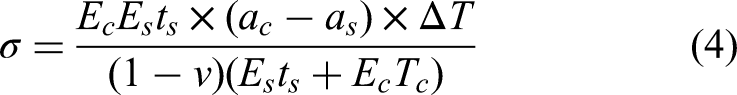
The SEM morphology of cracks near the interfaces of S2 and S5 and the corresponding thermal expansion coefficients of the materials in those areas:(a) S2, (b) S5.
Element content near non-uniform interface cracks(ωt.%).
In the equation, σ represents the thermal stress, while
Schematic representation of thermal stress cracking.
In addition to the aforementioned macrocracks, microcracks are also distributed throughout the coating, as illustrated in Figure 10. As seen in Figures 10(a) and (b), the length and width of these microcracks are significantly smaller than those of the macrocracks, and they predominantly form within the columnar grain regions. Furthermore, the orientation of these microcracks aligns with the growth direction of the columnar grains. Firstly, Cu has a positive mixing enthalpy with Fe and Cr (respectively +13 and +12 kJ/mol), while its mixing enthalpy with Ni is close to zero (+4 kJ/mol). This asymmetry causes Fe, Cr, and Ni to preferentially form FCC solid solutions, while Cu is excluded from the residual liquid phase during solidification. At the same time, the extremely high cooling rate of the laser cladding (up to 3.7 × 10⁴ K/s) limits the reverse diffusion of solutes, resulting in the continuous expulsion of Cu from the solidification front, which continuously accumulates in the residual liquid phase. Eventually, a low-melting-point liquid film (with a melting point of approximately 1080°C) forms in the intergranular and dendritic regions. These liquid films remain liquid after the surrounding matrix has solidified and cannot withstand the tensile stress generated by solidification and thermal contraction, thus causing solidification cracks along the grain boundaries (as shown in Figure 10).The growth process of these cracks can be generally summarized as follows: At the base of the molten pool, emerging grains preferentially grow in a direction perpendicular to the base. Due to the rapid solidification of laser cladding, the solid-phase temperature of the molten pool decreases within a distinct critical temperature range. The extremely fast solidification rate hinders the complete homogenization of the liquid metal in the molten pool; thus, during the solidification process of the molten pool, the redistribution of solutes is insufficient, and the low-melting-point components are pushed to the grain boundaries, forming a brittle liquid phase film that hinders stress transmission and leads to crack initiation. 38 Cracks arising from the presence of low-melting-point liquid films are generally considered solidification cracks. 39 Concurrently, solidification cracks typically manifest as intergranular fractures, 40 which aligns with the observed results. Figure 10(d) illustrates a simplified schematic of the microcracking mechanism.
Conclusion
In this study, laser cladding technology was utilized to fabricate FeCr0.5NiCu0.5 multi-principal element alloy coatings on 12Cr1MoV heat-resistant steel at different scanning speeds. The research systematically explored the microstructure, phase structure evolution, types of cracks, and their formation mechanisms.
The findings indicate that increasing the scanning speed significantly enhances the dilution rate of the coating (ranging from 24.1% to 62.1%), which leads to greater instability in coating quality while exerting minimal influence on the melt pool width. The microstructure of the FeCr0.5NiCu0.5 multi-principal element alloy coating includes a columnar grain region at the base, equiaxed grains in the middle, and coarse dendritic and dendritic structures at the top. As the scanning speed increases, the secondary dendrite arm spacing decreases, resulting in a refined microstructure. Furthermore, even slight changes in scanning speed lead to a notable rise in the cooling rate, from 2.68 × 10³ K/s to 3.7 × 10⁴ K/s, though the phase structure of the coating remains unaffected. The study also identifies two types of cracks in the coatings: macroscopic cracks, caused by the mismatch in thermal expansion coefficients between the coating and substrate, and microscopic cracks, which result from the liquid film of high-concentration, low-melting-point Cu. These findings contribute valuable insights into optimizing laser cladding parameters for multi-principal element alloy coatings.
Footnotes
Acknowledgements
This work was supported by Chongqing Natural Science Foundation Innovation and Development Joint Fund (CSTB2022NSCQ-LZX0071), Natural Science Foundation of Chongqing (2024NSCQ-MSX3024), Provincial and Ministerial Co-constructive of Collaborative Innovation Center for MSW Comprehensive Utilization (shljzyh2021-01).
Author contribution(s)
Funding
The authors disclosed receipt of the following financial support for the research, authorship, and/or publication of this article: This work was supported by the Provincial and Ministerial Co-constructive Collaborative Innovation Center for MSW Comprehensive Utilization (Grant No. hjzyh2021-01) and the Natural Science Foundation of Chongqing (Grant Nos. CSTB2022NSCQ-LZX0071, 2024NSCQ-MSX3024, and CSTB2024NSCQ-MSX0019).
Declaration of conflicting interests
The authors declared no potential conflicts of interest with respect to the research, authorship, and/or publication of this article.