
Abstract
Stellite alloys are a kind of cobalt-based alloys, which have excellent properties and are widely used in numerous areas. However, the wear resistance of Stellite alloys is poor at room temperature. In this study, Stellite31 cladding layers added with 0%, 1%, 2% and 3% of Mo(wt-%) were prepared by laser cladding. The grain sizes were measured by scanning electron microscope images, the distributions of Mo were analysed by energy dispersive X-ray spectrometry, the physical phase compositions were analysed by X-ray diffractometer, and the wear resistance was evaluated by reciprocating friction wear tester and wet sand wear testing machine. The results showed that the grain sizes of the cladding layers decreased with the increase of Mo content, the wear loss of the cladding layers became lower and the friction coefficient decreased under the same test conditions. It was concluded that increasing the Mo content could improve the wear resistance of the Stellite31 cladding layer at room temperature.
Introduction
Stellite alloys are a kind of cobalt-based alloy with splendid high-temperature properties, wear and corrosion resistance, and impact resistance.1–3 Surface-modified materials created with Stellite alloys have a wide range of application contexts in the field of surface engineering. Due to the discrete distribution of hard phases, Stellite alloys can maintain high wear resistance in environments at high temperatures4–6 and have good service performance in combustion turbines, 7 high-temperature valves 8 and petrochemical components. 9 At room temperatures, Stellite alloys have advantages in some applications, too. Andrews et al. 10 compared the erosion resistance of Stellite6 and SS316 steel commonly used in hydraulic turbines under different impingement angles, and the results showed that the erosion mass loss of the Stellite6 alloy at any angle was smaller than that of SS316. Ding et al. 11 mentioned that Stellite6 alloy coating is often used to control valve seat sealing surfaces and developed a coating mixed with 70% Stellite3 and 30% Stellite21, the hardness and wear resistance were tested and proved to be better than Stellite6 alloy coating. Alvarez-Vera et al. 12 pointed out that Stellite alloys are extensively used to manufacture articular replacements for medical applications, and the effect of adding B4C on the wear resistance of Stellite6 and Stellite12 was studied.
However, it has been shown that the wear resistance of Stellite alloys are poor at room temperature. Kumar et al. 13 studied the wear behavior of Stellite and Cr3C2 coatings at different temperatures, and noted that the wear rate of Stellite alloy coating was lower than that of Cr3C2 coatings at high temperature after wear tests under the same conditions, but the opposite was true at room temperature; Daure et al. 14 compared the friction coefficient of Stellite6 alloy at different temperatures, and concluded that the friction coefficient of Stellite6 alloy was lower at high temperatures compared with room temperature environment, which indicated that the wear resistance of Stellite6 alloy at room temperature was lower than its wear resistance at high temperatures. Due to the low wear resistance, when the alloy layers are used at room temperature, on the one hand, the layers may fail and cause economic losses, on the other hand, the base materials which are protected may be destroyed directly, resulting in the loss of component function and even safety problems. Therefore, enhancing Stellite alloys’ wear resistance at room temperature is a crucial step in expanding their range of applications and lengthening the service life of their coatings.
The addition of Mo to alloy coatings was an effective way to improve the performance of alloy coatings.15–17 In terms of improving the wear resistance of coating materials, the increase of Mo content in coatings had a positive effect on the wear resistance was shown in numerous studies of various systems of materials. Ma et al. 18 conducted tests on iron-based alloy coatings with different Mo contents, and the results showed that with the increase of Mo content, the hardness of iron-based alloy coatings did not change significantly, but the wear resistance was improved. Xiong et al. 19 added different contents of Mo elements to the high C content of Ni-based alloy powder and found that with the increase of added Mo content, the higher the Mo2C hard phase content in the coating, effectively improving the wear resistance of Ni-based alloy. In studying the wear resistance of iron-based amorphous composite coatings, Jiang 20 proposes that the addition of a certain content of Mo is more conducive to the formation of amorphous, resulting in more amorphous/nanocrystalline composite structures, which has a great impact on the improvement of the wear resistance of the coatings. However, no studies have been reported on improving the wear resistance of Stellite alloy coatings at room temperature service by using this method.
Laser cladding is a process of instantaneous fusion of powders of different compositions and properties with the substrate surface material by a high-power density laser beam on the surface of the substrate being protected. In the selection of coating preparation methods, the coating materials prepared using laser cladding technology have the advantages of low dilution rate, low void ratio, well bond with the substrate, and tight organisation. 21 In order to improve the room temperature wear resistance of Stellite alloy cladding layers, Stellite31 added with 0%, 1%, 2% and 3% of Mo(wt.-%) were prepared by laser cladding in this study. To study the effect of Mo on the properties of the Stellite31 alloy layer, scanning electron microscope (SEM) images of the layer surfaces were collected, and phase analysis was performed by X-ray diffractometer (XRD). To study the effect of Mo on the wear resistance of the Stellite31 alloy layer, a reciprocating friction and wear test was carried out, and the morphology of the wear marks was collected by SEM to analyse the mechanism. At the same time, the wet sand wear test was made to strengthen the proof of the conclusion.
Materials and methods
Materials and laser cladding process
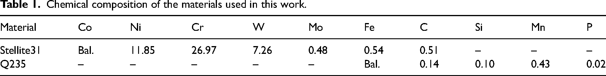
In this study, Stellite31 alloy cladding layers added with 0%, 1%, 2% and 3% of Mo(wt.-%) were prepared on Q235 substrate by laser cladding. The samples with Mo addition were recorded as St31, St31-1Mo, St31-2Mo and St31-3Mo from low to high addition amounts. The chemical compositions of Stellite31 alloy powder and Q235 substrate are shown in Table 1.
Chemical composition of the materials used in this work.
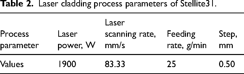
Rel-c3300w continuous fibre laser was used in this experiment. The laser is produced by Hubei RuiKe Fiber Laser Technology Co., Ltd, China. In order to improve the quality of the cladding layers, the surface rust and oxidation layer of Q235 substrate was first removed using 80# louvered wheel sandpaper, and the surface was scrubbed with anhydrous ethanol and acetone to ensure that the surface of the substrate material is free of impurities such as oil and rust. At the same time, in order to reduce the error caused by the effect of improper process parameters on the properties of the cladding layers for the study, the preparation process parameters were optimised by the control variable method during preparation. The process parameters used in this study were set as shown in Table 2.
Laser cladding process parameters of Stellite31.
The four different Mo contents of the cladding layers which were prepared by using the process parameters were of uniform thickness and good morphology, and the thickness of single cladding layers was all about 800 μm. To ensure that the substrate does not affect the test, a second layer is prepared using the same process parameters, and the first layer is allowed to cool completely before preparation, and surface impurities are removed by grinding.
Grain size measurement and phase analysis
Four Stellite31 alloy cladding layers with different Mo contents were wire cut to obtain 10 mm × 10 mm × 10 mm samples, and the surfaces of the specimens were ground to 2000 mesh step by step using sandpaper and polished to a mirror surface using a polishing machine. The surface was etched with aqua regia for 1–2 min, and after the surface lost its metallic lustre, the residual acid was cleaned with distilled water. The specimens were immersed in anhydrous ethanol and cleaned by shaking with an ultrasonic cleaner for 3 min. The specimens were observed by SEM for backscattering microstructure, and grain size was classified and measured by Image J. The distribution of Mo elements within the cladding layers was recorded by point scanning within the grains and at the grain boundaries by energy dispersive X-ray spectrometry (EDS), respectively. The physical phase composition of the specimens was analysed by XRD. The experimental parameters were: diffraction conditions were Cu target, X-ray sign wavelength 0.154178 nm, working current 100 mA, voltage 40 kV, diffraction range: 10°–100° and scan step 0.02°/s.
Microhardness test
FM-300 micro Vickers hardness tester, produced by FUTURE-TECH Co., Ltd, Japan, was used to test the microhardness change of the cladding section. The indenter of the microhardness tester is the pyramidal diamond indenter. The loading load was 500 g and the loading time was 15 s. The experiment adopts the parallel sampling method, starting from the surface of the side containing the cladding layers on the cross-section, and measuring a set of hardness values every 100 μm. Each sample was measured 3 times and averaged.
Wear resistance test
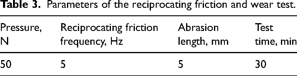
The cladding layers were cut into blocks with a dimension of 40mm × 25mm × 4 mm, and the surface was polished with sandpaper. The MFT-R4000 reciprocating friction and wear test machine, produced by Lanzhou Huahui Instrument Technology Co., Ltd, China, was used in the test. The friction pair was a steel ball used for the test was AISI 52100 steel with a diameter of 5 mm and a hardness of 700HV. The test parameters are shown in Table 3. About 0.3 g of lubricating oil was applied to the contact area of the ball samples before each test. The friction coefficient was automatically recorded by the computer. Each experiment was repeated 3 times to take the average to ensure the accuracy of experimental data.
Parameters of the reciprocating friction and wear test.
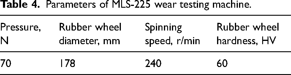
The cladding layers were cut into blocks with a dimension of 50mm × 25mm × 4 mm, and the surface was polished with sandpaper. The self-restrained MLS-225 wet sand wear testing machine was used in the test, the abrasive was 1.5 kg of 40–60 mesh quartz sand, and the mortar ratio was 1.5:1. The tester parameters are shown in Table 4, and the sample is pre-ground at 1000 revolutions before wear to produce prefabricated wear marks on the sample and eliminate the experimental errors caused by the surface roughness and uneven force of the sample. The pre-ground sample is cleaned and dried with alcohol and weighed as the original weight of the sample. The testing machine rotates 2000 times as an experiment cycle, a total of 20,000 times, each experiment cycle, with alcohol cleaning and drying after weighing, the weight loss of the sample is equal to the weight of the sample after pregrinding minus the weight of the formal wear.
Parameters of MLS-225 wear testing machine.
The schematic diagram of the wear test is shown in Figure 1.
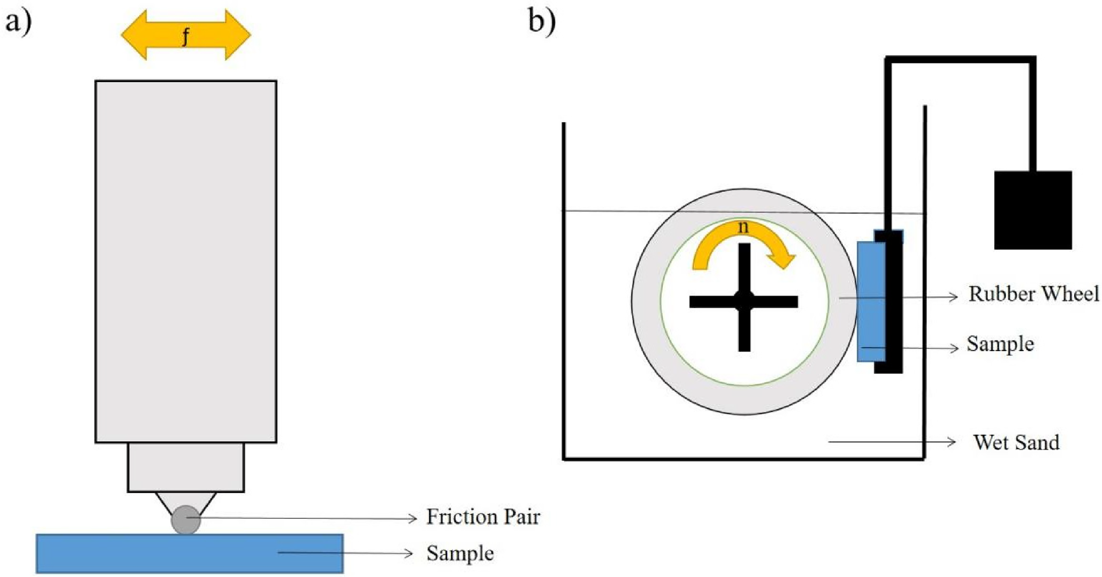
The schematic diagram of the wear test: (a) reciprocating friction and wear test; and (b) wet sand wear test.
Results and discussion
Grain size analysis
Compared with the inner grain, the atomic free energy at the grain boundary is higher, and it is easy to participate in chemical reactions. Therefore, after the surface of the four samples was eroded at the same time as aqua regia, the grain boundary was preferentially corroded, so as to be distinguished from the grain. Figure 2(a) to (d) are SEM images of the surface of Stellite31 cladding layers added with 0%, 1%, 2% and 3% of Mo(wt.-%), respectively, which clearly show the grains in the cladding layers. Image J was used to divide the grains along the white network structure, and the division results were shown in Figure 2(e) to (h).

Surface microstructure of the cladding layers and image J grain division results: (a), (e) St31; (b), (f) St31-1Mo; (c), (g) St31C-2Mo; and (d), (h) St31-3Mo.
Image J was used to calculate the Feret diameters of the meshed grains, and the frequency distribution of Feret diameters of each grain in each size range was calculated, and the results obtained are shown in Figure 3. The frequency distribution diagram of the grain Feret diameter of the four coatings is fitted, and the results are shown in the blue line in Figure 3, where D represents the sum or difference between the geometric mean and the standard deviation. The fitting results show that the average grain size in the cladding layer decreases with the increase of Mo content. In addition, the cumulative frequency of each size interval was fitted with a curve. The results are shown in Figure 3, where d90 represents the Feret diameter when the cumulative frequency is 90%. The fitting results show that < 90% of the grain size decreases with the increase of Mo content in the cladding layer. These results show that the increase in Mo content has an obvious effect on the grain refinement of the Stelltie31 cladding layer.
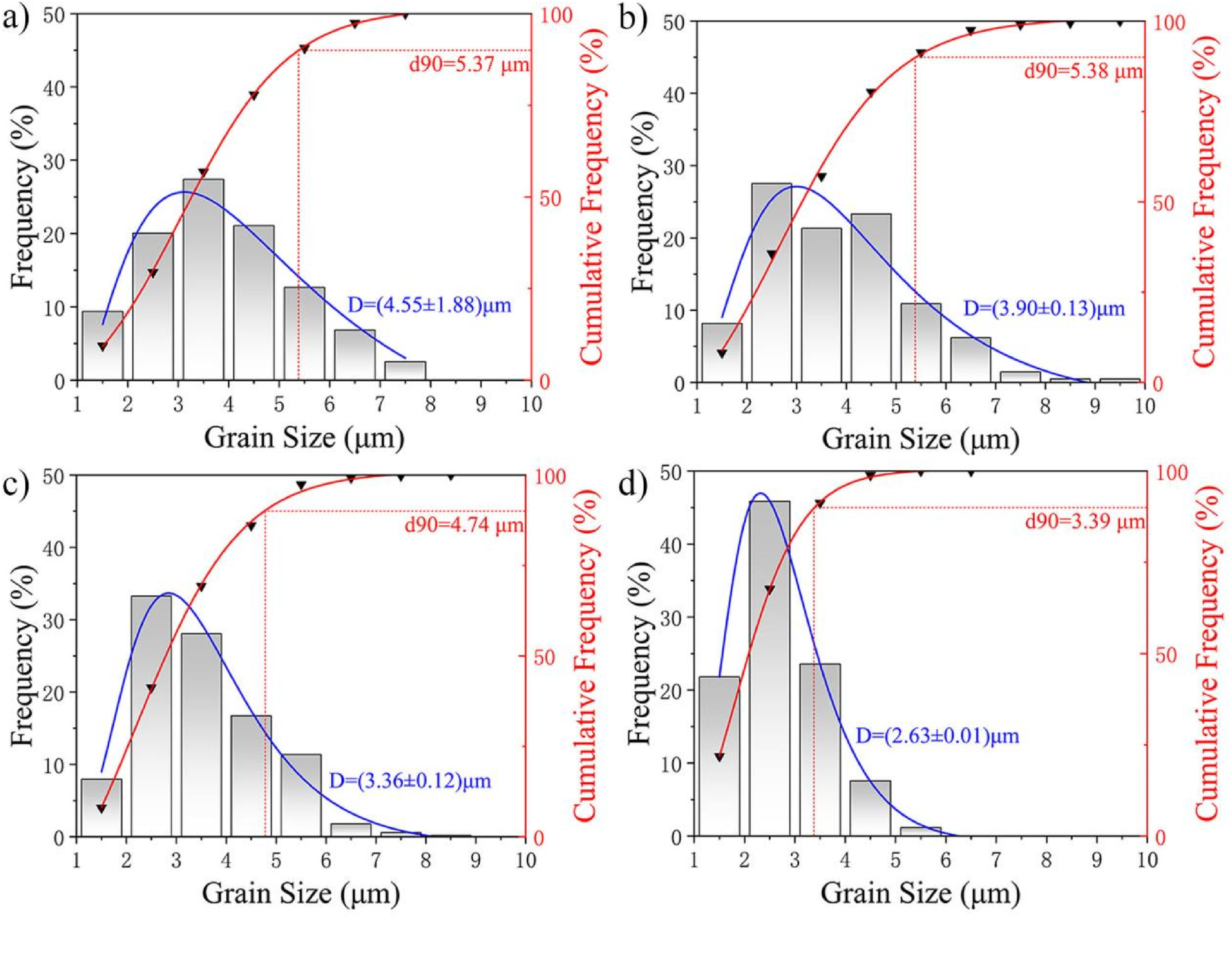
Grain size of the cladding layers: (a) St31; (b) St31-1Mo; (c) St31-2Mo; and (d) St31-3Mo.
The distribution of Mo elements in the layers was recorded by spot scanning of different phases of the four layers using EDS. The scanned spots are shown in Figure 4 and the recorded results are shown in Table 5.
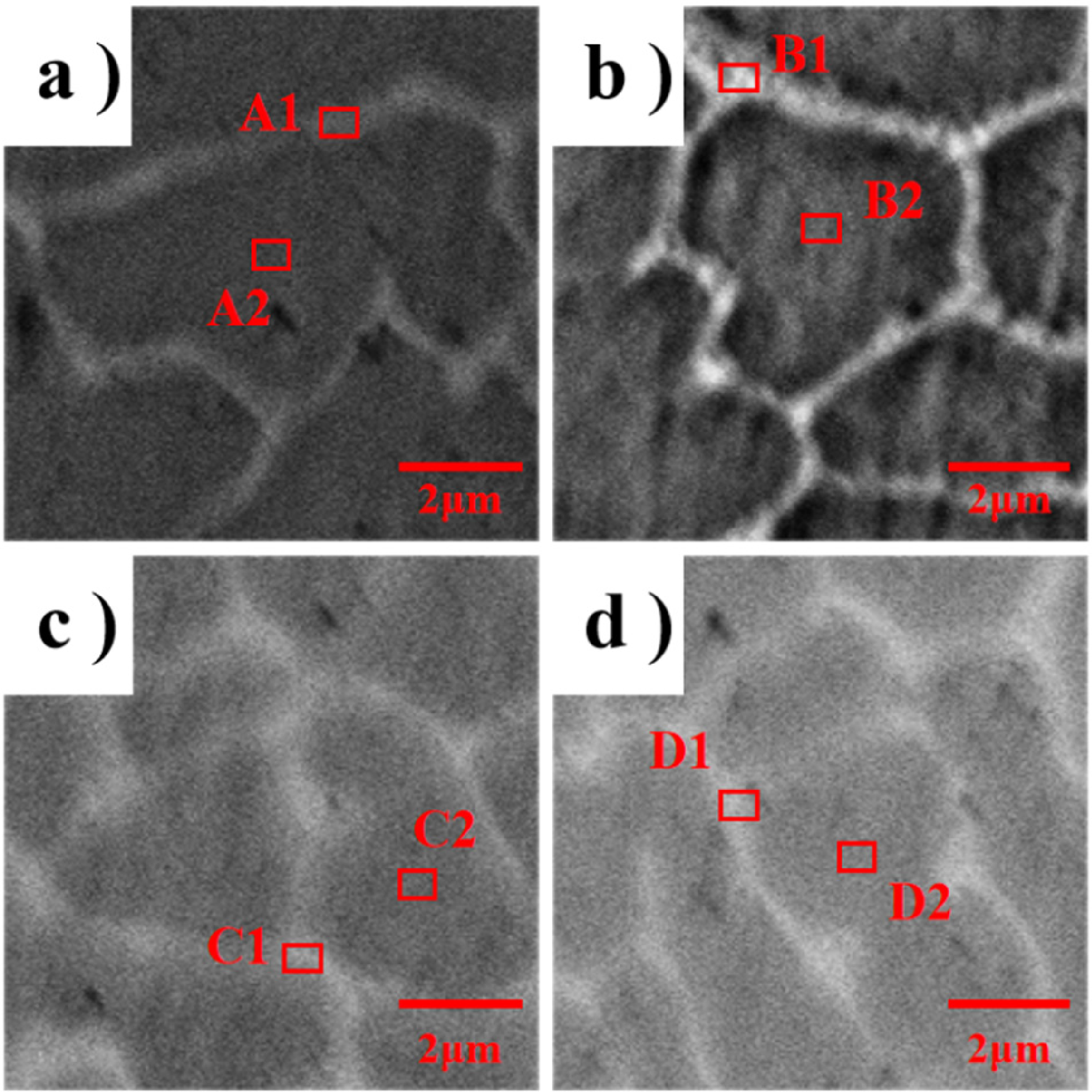
The scanned spots of the four layers: (a) St31; (b) St31-1Mo; (c) St31-2Mo; and (d) St31-3Mo.
Mo content of the scanned spots in wt.-%.
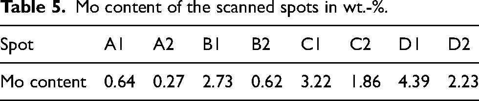
According to the data in Table 5, it can be seen that the Mo content at the grain boundaries in all four cladding layers is higher than the Mo content inside the grains. This is due to the fact that during the laser cladding process, the cladding layers cool faster and the Mo atoms solidify rapidly in the cladding layers, which is too late to solidify inside the grains.
Four cladding layers were analysed by XRD scanning, and the results are shown in Figure 5. As shown in Figure 5, the diffraction peaks of the four cladding layers are basically the same, mainly composed of γ-Co phase and M23C6 phase.
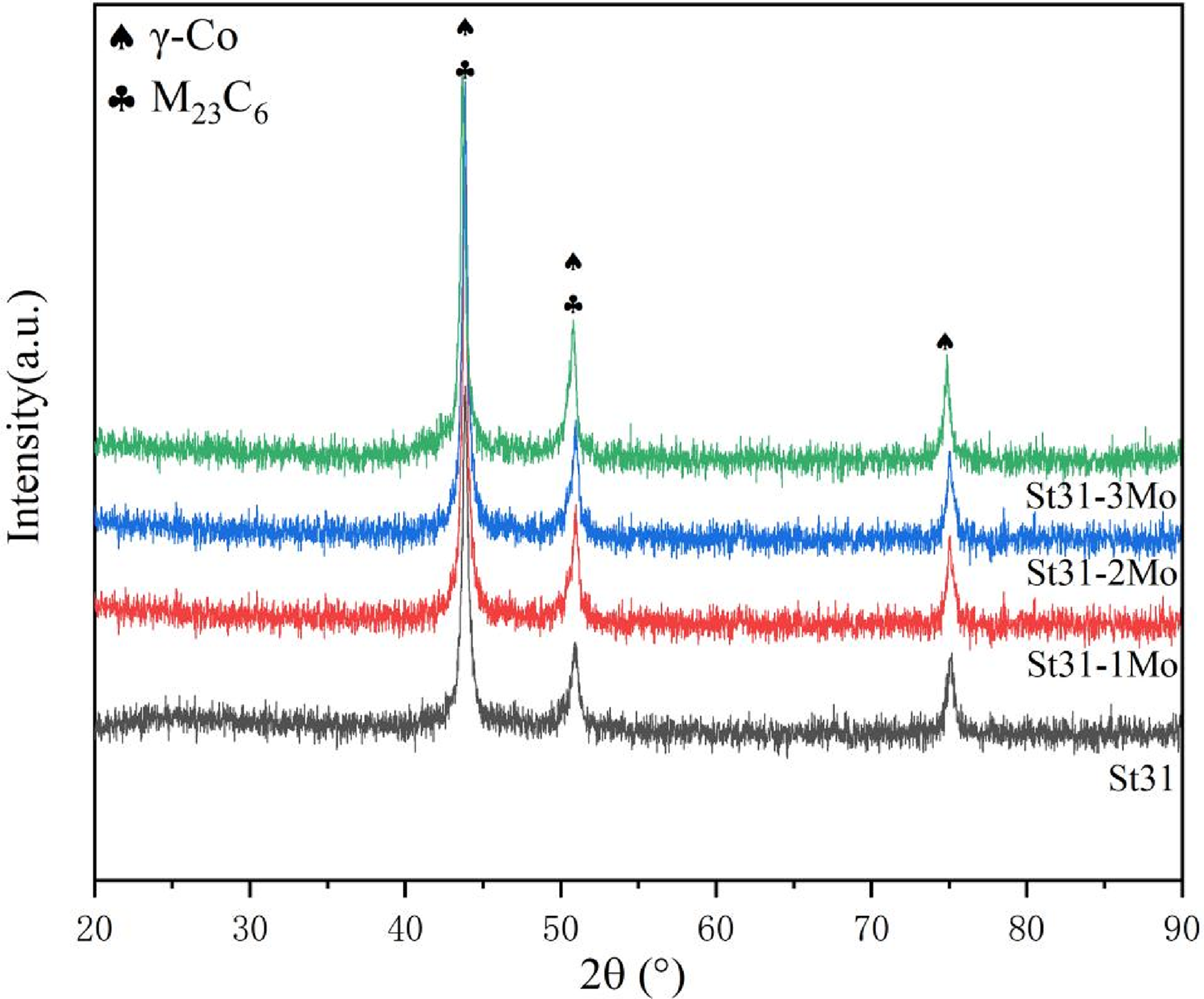
X-ray diffractometer (XRD) patterns of the cladding layers (M: Cr, Mo, W etc.).
Mo has a higher melting point. On the one hand, Mo may become a heterogeneous nucleation surface as an unmelted particle in the melt pool during laser cladding progress, thus increasing the nucleation rate. On the other hand, due to the enrichment of Mo outside the grain, the M23C6 carbides formed by Mo at the grain boundary play a nailing role, preventing the continuous growth of grains. Based on the above reasons, the addition of Mo is beneficial to the reduction of the grain size of the cladding layers.
Microhardness analysis
The microhardness of four Stellite31 alloy cladding layers with different Mo content is shown in Figure 6. It can be observed in the figure that the sample is composed of a matrix, heat-affected zone and coating. The hardness of the substrate is very small, about 160HV0.5, and the hardness of the heat-affected zone is higher than that of the matrix because the content of ferrite increases due to the complex thermal cycling effect. Because the process parameters of the four kinds of cladding layers are the same, the heat-affected zone is basically equal, so the range of the heat-affected zones of the four kinds of cladding layers is basically the same. The microhardness of the cladding layers showed that with the increase of Mo content, the average microhardness gradually increased. The carbide dispersed at the grain boundary will play a role of dispersion strengthening, increase the dislocation resistance, and thus improve the hardness of the cladding layers.
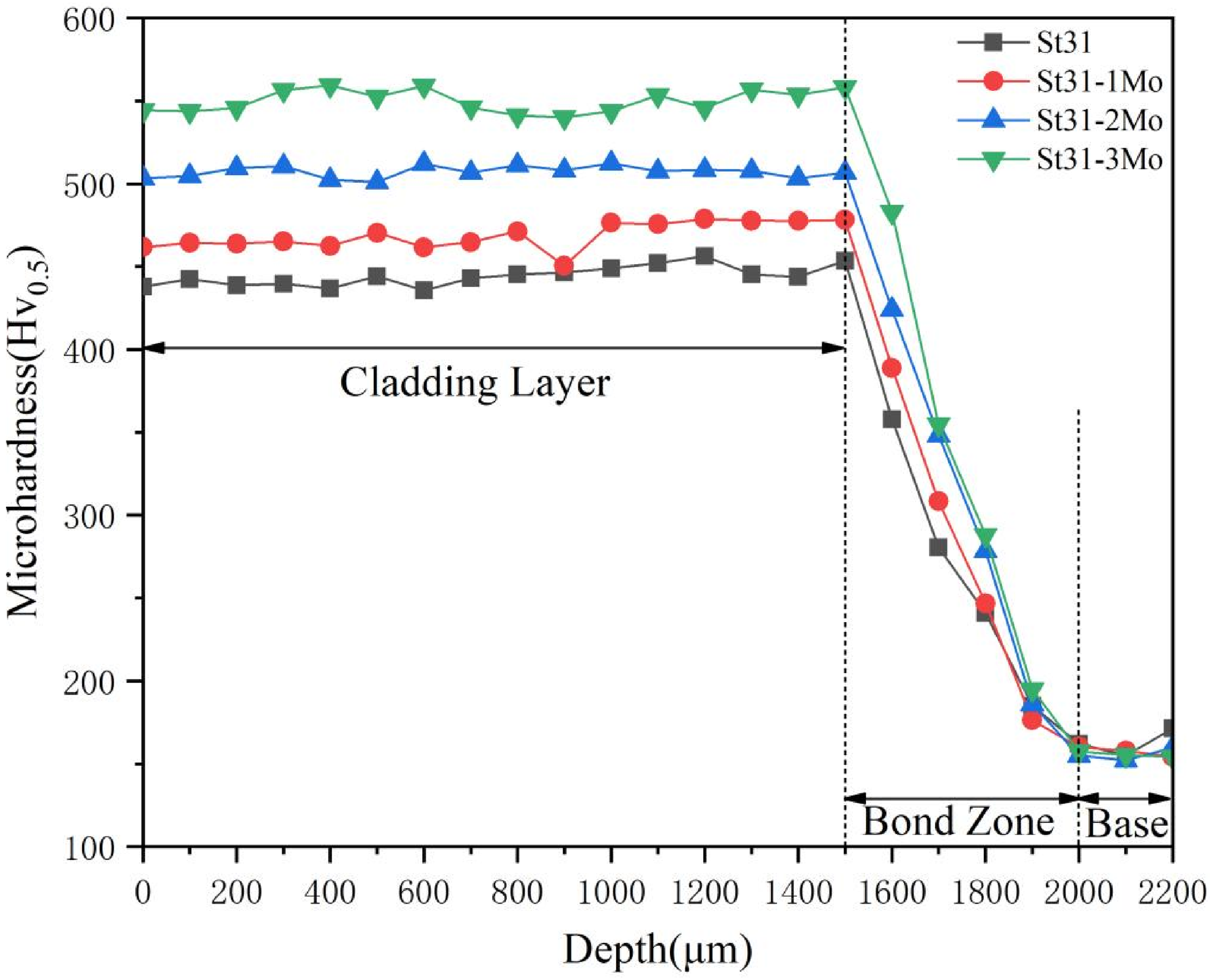
Microhardness of the cladding layers.
Wear resistance analysis
Friction coefficient analysis
Reciprocating friction and wear tests were carried out on the four samples, and the changes in the measured sample friction coefficient over time are shown in Figure 7. The friction coefficient of the four cladding layers showed the same trend with the test time. In the early stage of the test, due to the small contact points between the friction pair and the cladding layers, the friction coefficient was high, and the fluctuation range of the friction coefficient was also large due to the accumulation and removal of wear chips on the wear surface and the periodic local fracture of the wear surface. 22 With the gradual progress of the test, due to the deepening of the wear degree, the contact point between the friction pair and the cladding layers increases, and the friction coefficient gradually decreases and becomes stable. The friction coefficient of the four cladding layers remained basically unchanged after 11 min of the test. The average friction coefficients of the four cladding layers after 11 min of testing were calculated and linearly fitted. The results show that with the increase of Mo content, the friction coefficient after stabilisation of the cladding layers decreased gradually.
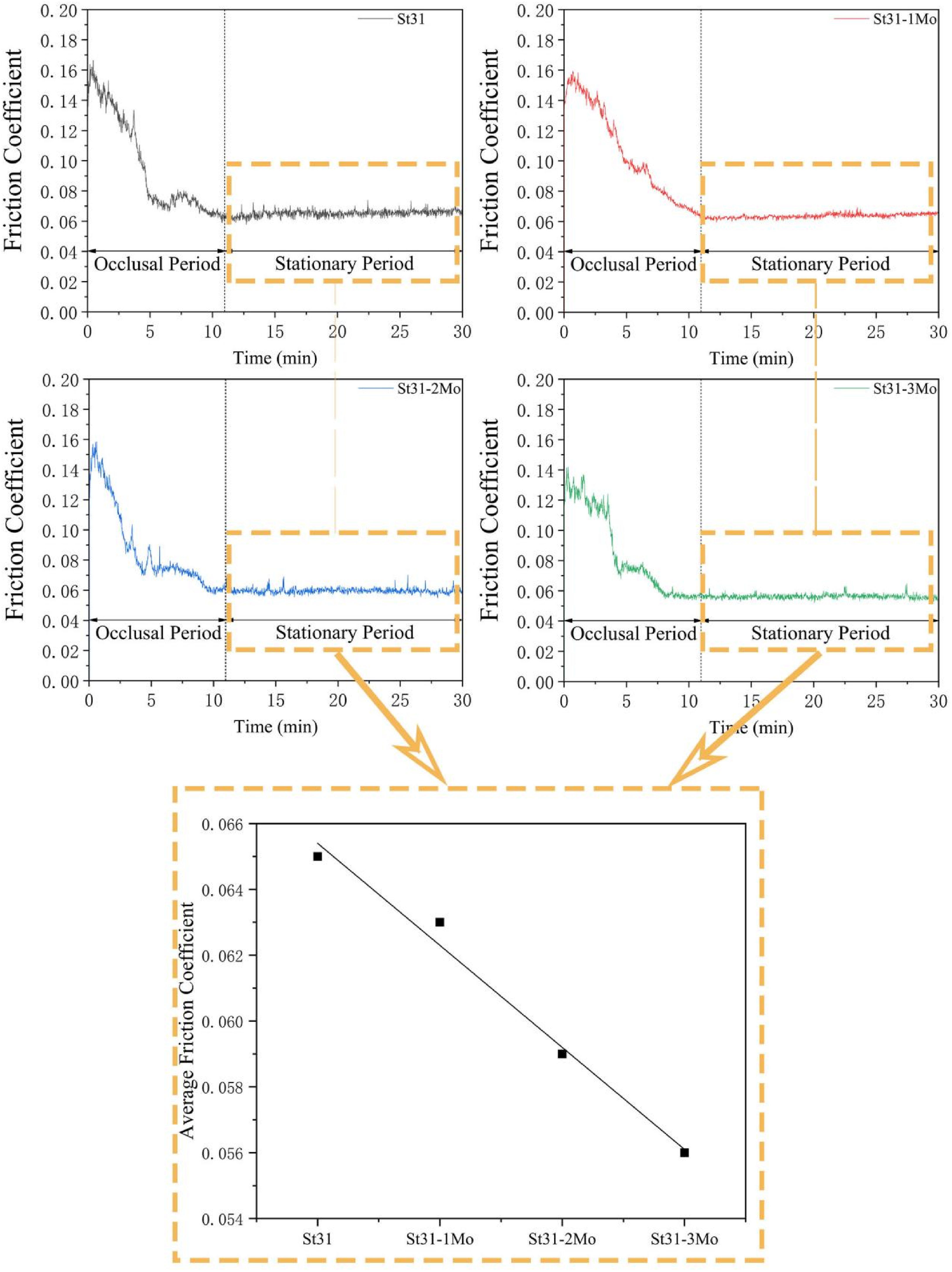
Friction coefficient curves and average friction coefficient after stabilisation of the cladding layers.
The wear morphologies’ SEM images of four cladding layers are shown in Figure 8. The SEM images show that there are many parallel grooves to the friction direction and particles at the wear marks of the four cladding layers, which indicates that the cladding layers were mainly subjected to abrasive wear in the test. At the same time, there are also spalled areas, and the initiation of micro-cracks can also be observed from the spalled areas in Figure 8(a) and (c), these physical morphologies indicated that the cladding layers suffered fatigue damage. In addition, there are also discontinuous corrugate areas different from furrows, which indicates that the four cladding layers were subjected to adhesive abrasion at the same time in the test.23,24 Therefore, under the test conditions, the four cladding layers were affected by abrasive wear, fatigue wear and adhesive wear.
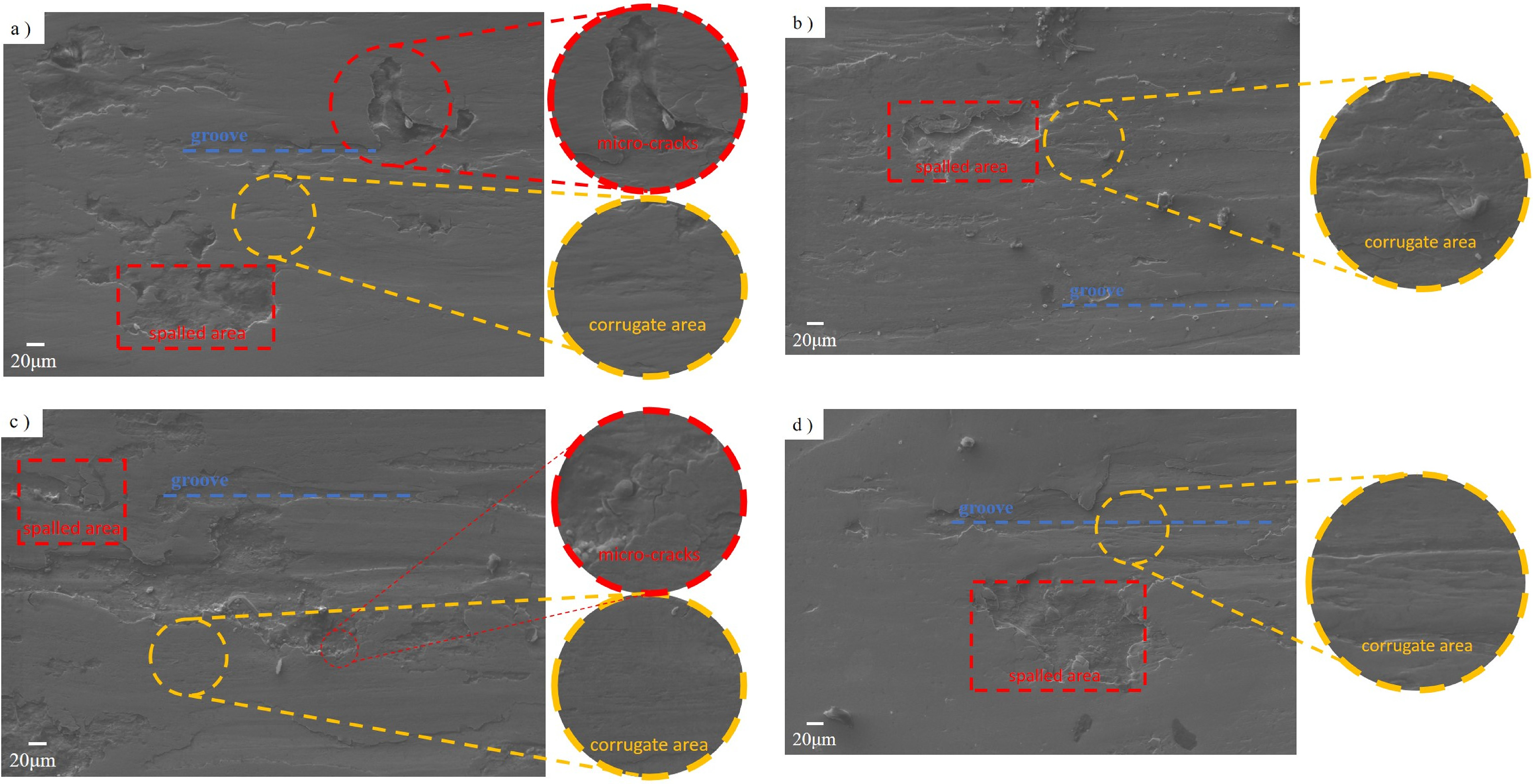
Wear morphologies of the cladding layers: (a) St31; (b) St31-1Mo; (c) St31-2Mo; and (d) St31-3Mo.
The wear morphologies show that under the same test conditions, due to the phases with lower hardness are more susceptible to the friction between the friction pair and the layer surfaces, and are more prone to plastic deformation, so they are first discharged from the layer surfaces. The hard phases are then pulled out as abrasive particles and cause the friction pair to wear the rest more directly. However, the finer the grain size of the same material, the more uniform the distribution of the hard phase, and the smaller the degree of peeling, which is also more conducive to hindering this wear effect, in addition, the finer grain size will also make the material surface roughness decreased. 25 For these reasons, the addition of Mo improves the frictional wear resistance of the material to a certain extent under the same test conditions, as shown by the decrease of the friction coefficient of the cladding layer with the increase of Mo content.
Wear loss analysis
Due to the wear loss that can often more intuitively characterise the wear resistance of a material, the wet sand wear test was carried out on the four samples to verify that the addition of Mo affects not only the friction coefficient but also the wear resistance of the cladding layers. The wear loss of the samples in each cycle and the linear fitting results are shown in Figure 9, k represents the slope of the fitted line, namely the wear rate of the cladding layers with the test. Figure 9 shows that under the same test period, the weight loss of the cladding layer decreases with the increase of Mo content, indicating that the wear resistance of the cladding layer increases with the increase of Mo content. In the wet sand wear test, due to the high abrasive hardness, the rubber wheel of the testing machine drives the sliding cutting coating, resulting in grooves. In addition, the repeated rolling of abrasive particles can also cause plastic deformation of the coating, leading to the generation and expansion of cracks. 26 Subsequently, the continuous cutting action of the increasing abrasive particles causes the gradual increase of the abrasive groove further to shift the edge towards the relatively soft area, eventually leading to the development of deeper grooves. 27 However, the smaller the grain size, the larger the grain boundary area, the higher the energy required for plastic deformation, and the more difficult it is to crack initiation and development. At the same time, the smaller hard phase is more evenly distributed in the cladding layer, which prevents contact between the abrasive particles and the outer part of the hard phase of the cladding layer to a certain extent. Based on the above reasons, the addition of Mo refines the grain of the cladding layer, thus reducing the wear amount of the cladding layer and increasing its wear resistance.
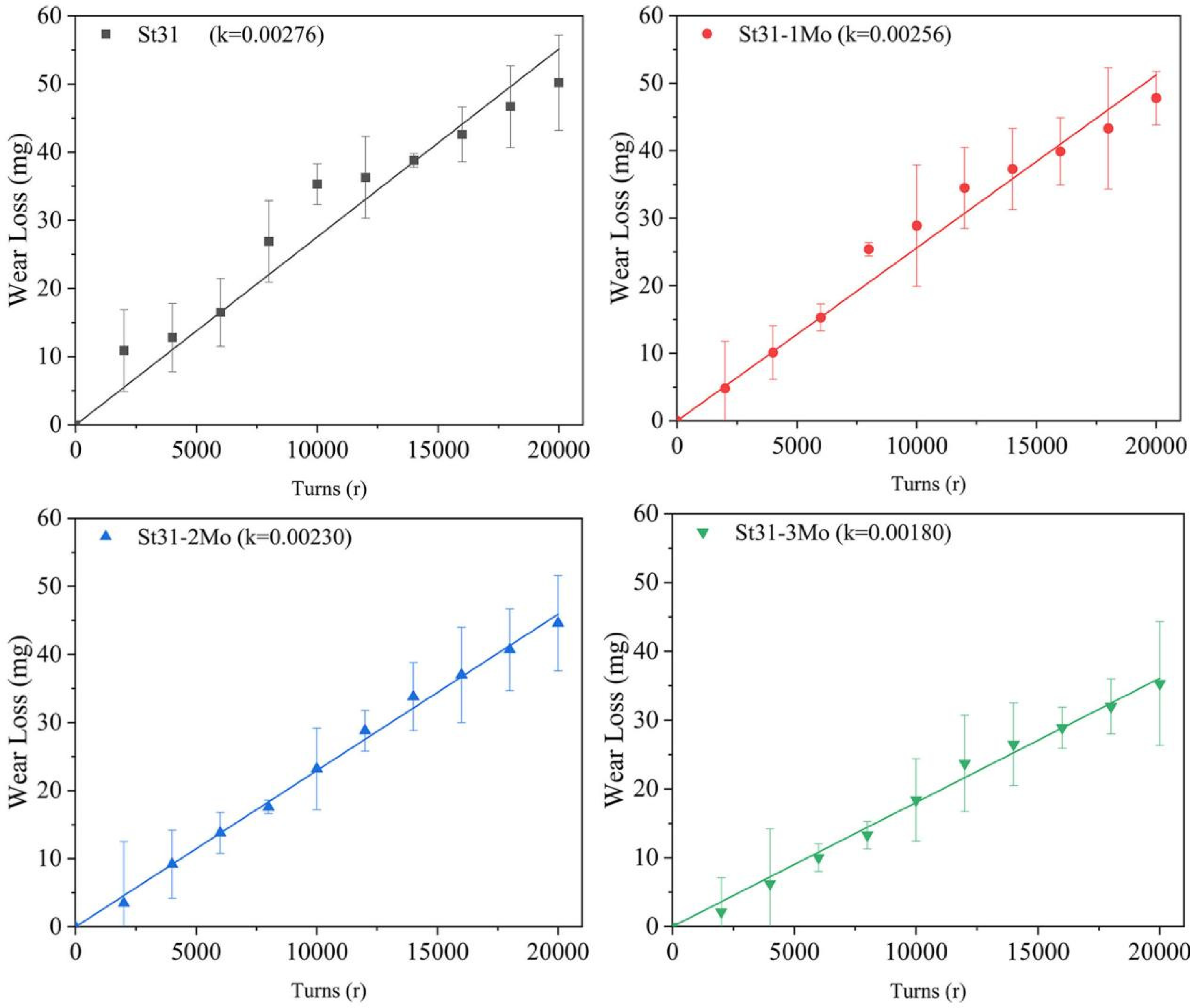
Wear loss curves of the cladding layers.
Conclusions
In this study, Stellite31 cladding layers added with 0%, 1%, 2% and 3% of Mo(wt.-%) were prepared by laser cladding, and the main conclusions obtained are as follows:
The average grain sizes of the cladding layers decrease and the proportion of small grains increases with the increase of Mo content. The results show that the Mo content at the grain boundary is higher than that in grain. The high melting point of Mo and carbide will nail the grain and inhibit the growth of the grain. Therefore, the addition of Mo can reduce the grain size of the laser cladding layer of the Stellite31 alloy laser cladding layer. The microhardness of the cladding layers gradually increased with the addition of Mo. The carbide dispersed at the grain boundary will play a role of dispersion strengthening, increase the dislocation resistance, and thus improve the microhardness of the cladding layers. The friction coefficient of the cladding layers gradually decreased, and the weight of abrasive wear loss gradually decreased with the increase of Mo content. Under the reciprocating friction and wear test, the four cladding layers were affected by abrasive wear, fatigue wear and adhesive wear. The test results were analysed in terms of grain refinement and wear formation mechanism and proved that the addition of Mo has a positive effect on the wear resistance of the Stellite31 laser cladding layer.
Footnotes
Declaration of conflicting interests
The author(s) declared no potential conflicts of interest with respect to the research, authorship, and/or publication of this article.
Funding
The author(s) received no financial support for the research, authorship, and/or publication of this article.