
Abstract
Spark plasma sintering was employed to fabricate dense titanium carbide–iron composite coatings on tungsten carbide-cobalt (8 wt.% cobalt) substrates. The choice of titanium carbide–iron was motivated by its high hardness, good thermal-shock resistance, lower density compared with tungsten carbide–cobalt, and the avoidance of cobalt-related health concerns, making it a promising candidate for cutting and forming tools. Powder mixtures containing different iron fractions (10, 20, and 30 wt%) were consolidated at 1500 °C. Phase composition was identified by X-ray diffraction, and microstructure was examined by field-emission scanning electron microscopy and energy-dispersive X-ray spectroscopy. The influence of iron content on densification, microstructural development, mechanical integrity, and wear performance was systematically evaluated. Bonding strength decreased with lower iron due to reduced plastic accommodation, while hardness increased from ∼11 to ∼15 GPa with decreasing iron. Tribological tests showed that reducing iron content markedly decreased the coefficient of friction (from ∼0.68 to ∼0.41) and wear rate (from 3.2 × 10⁻⁴ to 5.6 × 10⁻⁶ mm3/N·m). Microscopy of worn surfaces indicated a transition from delamination-dominated wear in iron-rich coatings to oxidation-assisted protective tribofilm formation in titanium carbice-rich coatings. These findings highlight that the interplay between densification, microstructure, and microscopic defects governs both mechanical integrity and wear performance.
Keywords
Introduction
Many industrial components in transportation, energy, marine, and aerospace applications operate in abrasive and corrosive environments that degrade surfaces and shorten service life. Surface and coating engineering provide an effective route to extend component lifetime by improving wear resistance, corrosion resistance, and interfacial integrity.1,2 Among hard, wear-resistant systems, carbide-based composites—particularly tungsten carbide in combination with cobalt as a binder, and titanium carbide in combination with metallic binders such as cobalt or iron—have long been used for cutting and forming tools.3–5
Titanium carbide–iron composites offer several advantages relative to tungsten carbide–cobalt composites. These include lower density, better thermal-shock tolerance, retention of properties at elevated temperature, and avoidance of cobalt-related toxicity. Reported hardness values span approximately 55–70 HRC depending on the relative fraction of iron and titanium carbide, and wear resistance can exceed that of tungsten carbide–cobalt by about 20% in suitable microstructural architectures. Such characteristics make titanium carbide–iron coatings attractive for demanding applications such as cutting inserts, forming dies, and other wear-exposed mechanical components.6–10
Previous studies have deposited titanium carbide–iron coatings using a variety of methods including electrical discharge coating, laser cladding, plasma spraying, and tungsten-inert-gas arc methods. Although each of these techniques has shown promise, they often produce coatings with residual porosity, incomplete densification, and weaker interfaces with the substrate, all of which can lead to premature failure under service conditions. Comparisons among these methods have indicated that while rapid solidification routes can yield refined structures, they may also increase internal stresses and susceptibility to cracking.11–16
Spark plasma sintering enables rapid densification under concurrent mechanical pressure and pulsed electric current in a low-pressure or vacuum environment, producing nearly full-density materials with refined microstructures. While spark plasma sintering has been widely applied for bulk materials, it can also be adapted to apply dense coatings by placing powder blends on a substrate inside a die and consolidating them under uniaxial load.17–19 In this approach, the iron fraction plays a critical role. Higher iron contents facilitate densification through plastic flow and possible transient liquid formation, but may simultaneously promote microscopic defects such as fine microcracks and delamination at the coating–substrate interface. Lower iron contents, on the other hand, enhance hardness and oxidation resistance but reduce plastic accommodation, which can decrease bonding strength.20,21
These competing factors strongly influence both the mechanical integrity and the tribological response of titanium carbide–iron coatings. According to principles of materials science and mechanical behavior of materials, delamination-dominated wear is expected in iron-rich coatings where subsurface crack nucleation occurs, whereas oxidation-assisted tribofilm formation is favored in titanium carbide-rich coatings, resulting in reduced coefficient of friction and improved wear resistance.8,12,22
The present study investigates titanium carbide–iron composite coatings with different iron fractions consolidated by spark plasma sintering. Emphasis is placed on phase formation, densification behavior, microstructural evolution, interfacial integrity, bonding strength, hardness, and tribological performance. Special attention is given to the influence of iron content on the development of microstructural features and microscopic defects, and to how these factors govern the observed wear mechanisms and mechanical properties. The insights gained are expected to contribute to the rational design of carbide-based composite coatings for high-performance industrial applications.
Materials and methods
Materials
In this research, titanium powder with a purity greater than 99% (Merck, particle size smaller than 45 micrometers), iron powder with a purity greater than 99% (Sigma Aldrich, particle size smaller than 45 micrometers), and amorphous carbon powder with a purity greater than 99% (particle size smaller than 0.5 micrometers) were employed as the starting raw materials. Stearic acid with a purity of 99% (Merck) was used as a process control agent in order to prevent cold welding of the powders during milling.
The substrates were discs made of tungsten carbide containing 8 weight percent cobalt. Each disc had a diameter of 15 millimeters and a thickness of 5 millimeters, and these substrates were used for deposition of the coatings.
Mechanical milling
Titanium carbide–iron composites were synthesized through mechanical alloying followed by spark plasma sintering. First, titanium, iron, and amorphous carbon powders were weighed in different proportions according to the compositions summarized in Table 1. Each mixture of raw materials, with a total batch weight of 60 grams, was placed into a 500 milliliter hardened steel container. Stearic acid (1 weight percent) was added as a process control agent to reduce adhesion between powders and to the container walls.
The compositions and sintering parameters of the coated samples
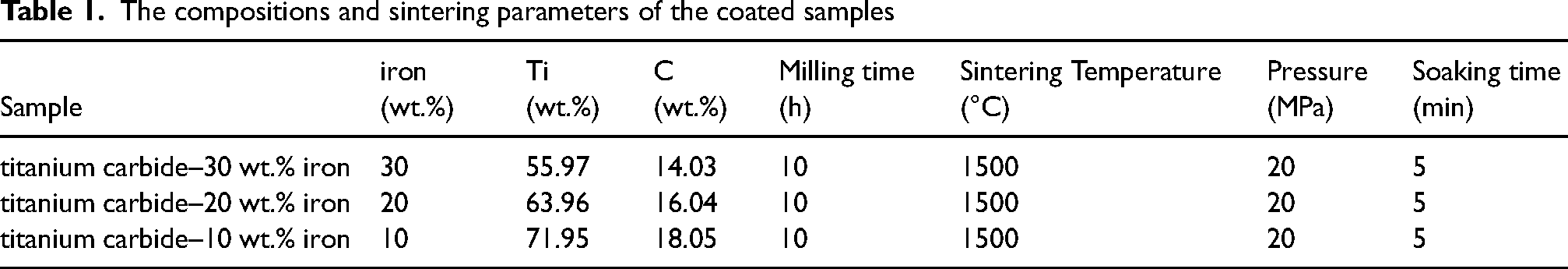
The milling process was carried out at a rotation speed of 300 revolutions per minute with a ball-to-powder weight ratio of 10:1. Hardened steel balls with diameters of 10, 15, and 20 millimeters were used simultaneously to enhance the milling efficiency. To avoid oxidation of the powders, high-purity argon gas (99.999%) at a pressure of 2.5 bar was continuously purged into the containers during milling. The milling time for all compositions was 10 h.
Coating procedure
Prior to coating, the tungsten carbide–cobalt substrates were mechanically polished using silicon carbide abrasive papers up to grit number 2000, followed by sandblasting with silicon carbide particles of 45 micrometers. After surface preparation, the substrates were cleaned in deionized water and then rinsed with acetone in an ultrasonic bath to ensure complete removal of surface contaminants.
For coating, one gram of each mechanically milled powder mixture was uniformly spread on the surface of the prepared substrates. The coated substrates were then placed into a cylindrical graphite die with an inner diameter of 15 millimeters. Consolidation was performed using a spark plasma sintering system (Easy Fashion Industry, China). The chamber was evacuated to a vacuum pressure of 9 Pascal, and the samples were heated at an average heating rate of 40 °C·min−1 up to a final sintering temperature of 1500 °C under a uniaxial pressure of 20 MPa. The soaking time at the maximum temperature was 5 min. After sintering, the coated samples were cooled at a rate of 10 °C per minute down to room temperature under vacuum conditions. The compositions and sintering parameters of the coated samples are summarized in Table 1.
Characterization and microstructure analysis
Phase identification of the fabricated coatings was carried out using X-ray diffraction (Philips PW3710) operated at an accelerating voltage of 30 kV and a current of 40 mA. X-rays were generated from a copper Kα source (wavelength 1.54 Å). The scanning range was set from 20° to 80° in 2θ with a step size of 0.02°. The diffraction patterns were analyzed using X’Pert HighScore Plus software for phase determination.
The microstructure of the coatings was examined by field-emission scanning electron microscopy (FESEM, Zeiss Sigma-VP, Germany). Energy-dispersive X-ray spectroscopy attached to the FESEM was employed to determine the local chemical composition and distribution of elements in the coated samples.
Mechanical and tribological properties
The hardness of the coatings was measured using a Vickers microhardness tester (Akashi MVK-H21, Japan) with an applied load of 200 grams and a dwell time of 15 s, according to the ASTM E384 standard. 23
The bonding strength of the coatings was evaluated using a pull-off tensile test based on ASTM D4541. 24 For this purpose, the coated surfaces were bonded to steel cylinders using a high-strength adhesive with a shear strength of 300 MPa. The samples were then subjected to tensile loading using a universal testing machine (SANTAM, Iran).
The tribological behavior of the coatings was evaluated using a pin-on-disk tribometer following the ASTM G99 standard. A tungsten carbide ball with a diameter of 6 mm was used as the counter-body. Tests were performed under dry sliding conditions at room temperature (≈22–25 °C). The applied normal load was 10 N, the sliding speed was 0.1 m.s−1, and the total sliding distance was 300 m. After testing, the weight loss of the specimens and the coefficient of friction were measured to assess the wear performance of the coatings. 25
The specific wear rate Q of the specimens was calculated using the following relation 26 :
Q = V / (N × S)
where Q is the specific wear rate (mm3·N−1·m−1), V is the worn volume (mm3), N is the applied normal load (N), and S is the sliding distance (m).
The worn volume V was estimated from the wear-track geometry by the relation:
V = π × R × d × r
where R is the rotational radius of the pin (mm), d is the width of the wear track (mm), and r is the radius of the pin (mm). Units must be used consistently when applying these relations.
Archard's law relates the specific wear rate Q to hardness H through the dimensionless wear coefficient K as:
Q = K / H
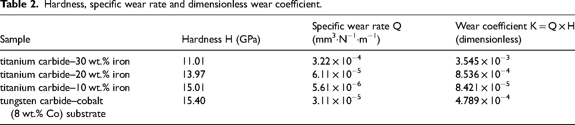
where H is the hardness (in consistent units) and K is an empirical, dimensionless wear coefficient when consistent unit conversions are applied. In this work H is reported in GPa and Q in mm3·N−1·m−1; K values reported in Table 2 were computed using these units and are therefore presented for direct comparison between samples (unit conversions applied as necessary to maintain dimensional consistency).
Hardness, specific wear rate and dimensionless wear coefficient.
Results and discussion
Sintering behavior
The heating profiles and punch displacement as functions of sintering time for the titanium carbide–30 wt.% iron, titanium carbide–20 wt.% iron, and titanium carbide–10 wt.% iron coatings are plotted in Figure 1. All specimens were heated with an average rate of 40 °C·min−1. The evolution of punch displacement during the thermal cycle can be divided into three distinct stages.
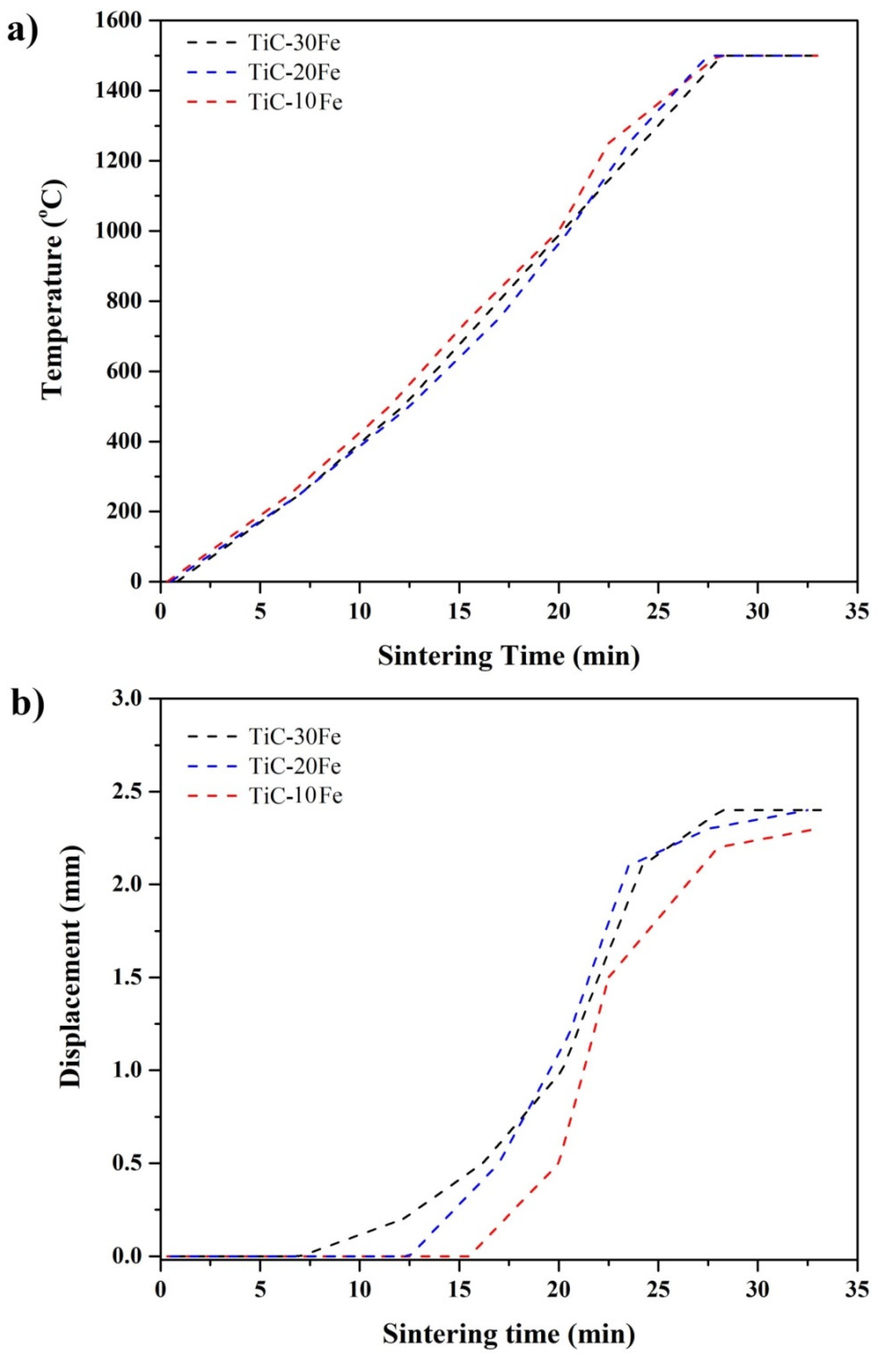
(a) Heating curve (b) punch displacement vs. sintering time of sintering time of the sintered coatings: TiC–30Fe (solid line), TiC–20Fe (dashed line), and TiC–10Fe (dotted line).
In Stage I (initial heating) there is no measurable displacement, indicating a closed packing configuration and limited particle rearrangement. Stage II is characterized by a rapid increase in displacement, which reflects active densification and is attributable to a combination of particle rearrangement, plastic deformation of metallic constituents, sintering shrinkage, and possible reaction-sintering between titanium and carbon. The onset temperature for observable displacement shifts systematically with composition: samples with higher iron content exhibit displacement at lower temperatures, consistent with enhanced plasticity and faster densification kinetics provided by the metallic phase. Stage III corresponds to the dwell at the peak temperature (1500 °C). During this period a modest additional displacement occurs, indicating continued pore elimination and final microstructural consolidation. The titanium carbide–30 wt.% iron coating shows the largest cumulative displacement among the three compositions, which may reflect the presence of a greater fraction of transient liquid or more extensive plastic flow in the iron-enriched mixture. 22
The combined application of uniaxial pressure and vacuum conditions reduces the likelihood of molten iron exudation or formation of undesired secondary phases during sintering. This is supported by the negligible mass change measured before and after sintering, which suggests retention of the nominal composition and little material loss during the run. 27
A deeper analysis of the displacement behavior highlights the crucial role of iron in governing the sintering kinetics. With increasing iron fraction, enhanced diffusion pathways are introduced through the metallic network, which promotes particle rearrangement and accelerates neck growth between adjacent grains. The earlier onset of densification in iron-rich compositions can therefore be attributed not only to plastic deformation but also to improved diffusional transport. Conversely, the smaller final displacement observed in the iron-lean coating (titanium carbide–10 wt.% iron) suggests a reduced contribution from plastic flow and possible pinning of particle contacts by the rigid titanium carbide framework. This finding indicates that the balance between ceramic reinforcement and metallic binder strongly dictates the consolidation route during spark plasma sintering. Moreover, the relatively larger displacement in the iron-rich sample may have microstructural implications such as the development of residual stresses or incipient liquid-phase-assisted sintering, which could subsequently influence mechanical integrity and tribological behavior. These insights underline the necessity of optimizing the iron fraction to achieve a compromise between densification efficiency, microstructural stability, and final coating performance.
Characterization and microstructure
The X-ray diffraction patterns recorded for the three compositions reveal titanium carbide and metallic iron as the principal crystalline phases (Figure 2). The patterns are consistent with in-situ formation of titanium carbide from the reaction of titanium and carbon during the thermal cycle; no additional crystalline secondary phases were detected within the sensitivity limits of the measurement. A systematic variation in peak intensities is evident: iron peak intensities decrease while titanium-carbide peak intensities increase as the iron content is reduced from 30 wt.% to 10 wt.%, confirming the designed compositional trend among titanium carbide–30 wt.% iron, titanium carbide–20 wt.% iron and titanium carbide–10 wt.% iron. It is worth noting that ex-situ evaluations of the as-milled Ti/Fe/C powder (10 h), including X-ray diffraction, did not reveal the formation of new crystalline phases above the instrument detection limit. The milling process therefore primarily resulted in intimate mixing and activation of the powder constituents, while the formation of TiC is attributed mainly to in-situ reactions during the subsequent SPS thermal cycle.
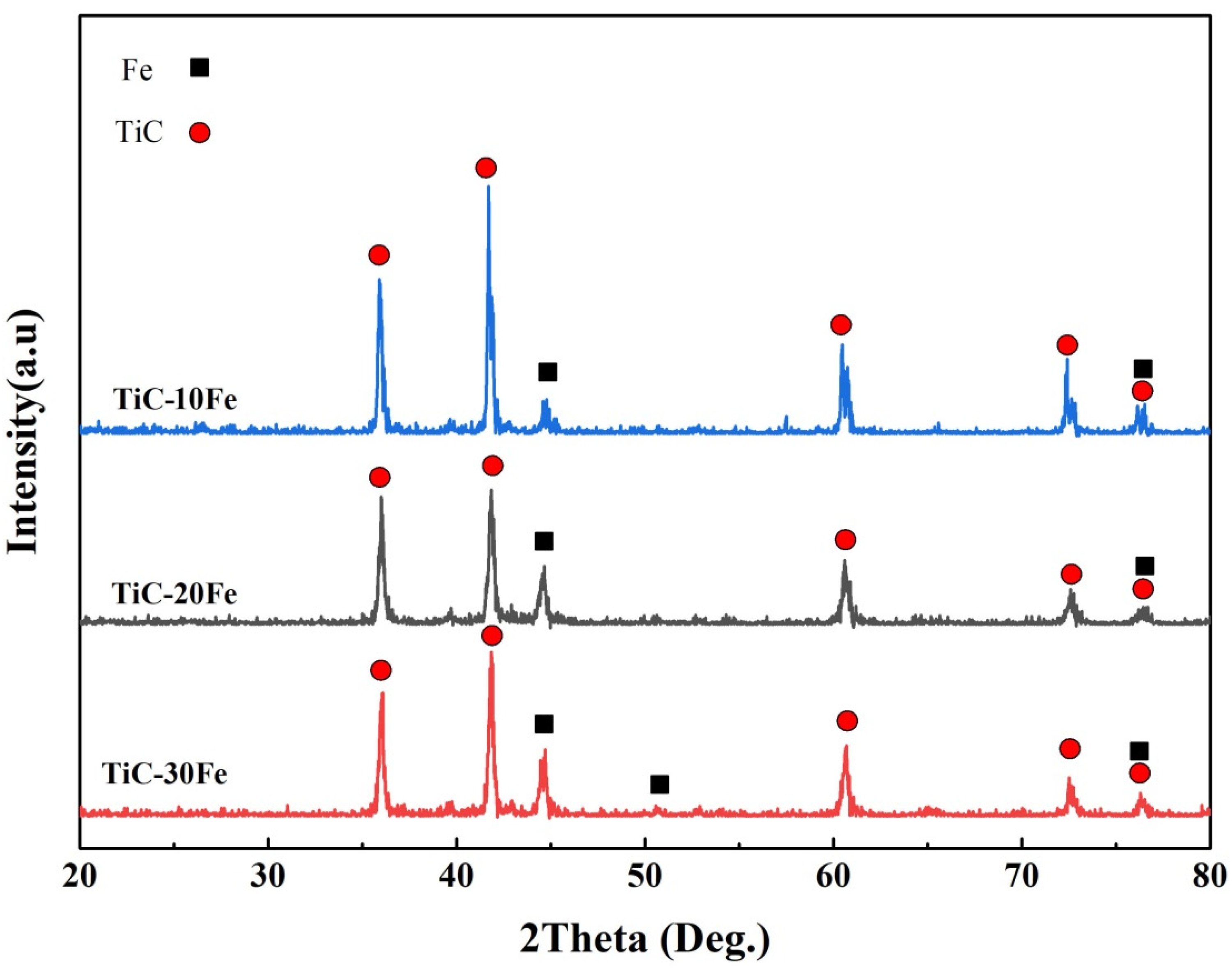
X-ray diffraction patterns of the sintered titanium carbide–30 wt.% iron, titanium carbide–20 wt.% iron and titanium carbide–10 wt.% iron coatings via spark plasma sintering method.
Cross-sectional FESEM demonstrates that the coatings are applied uniformly and that their thicknesses are comparable across the series (Figure 3). The measured average thicknesses are 894 ± 35 µm (titanium carbide–30 wt.% iron), 879 ± 34 µm (titanium carbide–20 wt.% iron) and 842 ± 64 µm (titanium carbide–10 wt.% iron). As shown in Figure 3, no open porosity or macroscopic interfacial delamination was observed within the resolution limits of the applied imaging; the coating–substrate interfaces exhibit continuous contact with the tungsten-carbide–cobalt substrate. These observations indicate effective consolidation during spark plasma sintering and an apparently sound bond between the composite coatings and the underlying substrate. Furthermore, the cross-sectional FESEM micrographs, including contrast variations at higher magnification, show no evidence of new or undesirable phase formation at the coating–substrate interface.
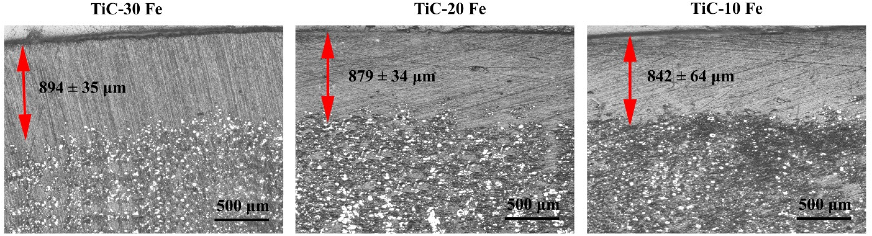
Secondary electron FESEM images of the cross section of the coated specimens.
Back-scattered electron images of the coating surfaces reveal a clear two-phase microstructure: relatively bright islands corresponding to the iron phase dispersed within a darker, continuous matrix corresponding to titanium carbide (Figure 4). The area fraction of the bright iron-rich regions visibly decreases with lower iron content, and iron particles are distributed relatively uniformly within the titanium-carbide matrix for all compositions. The absence of detectable porosity in the presented surface and cross-section images further supports the near-full density achieved by the applied processing route.
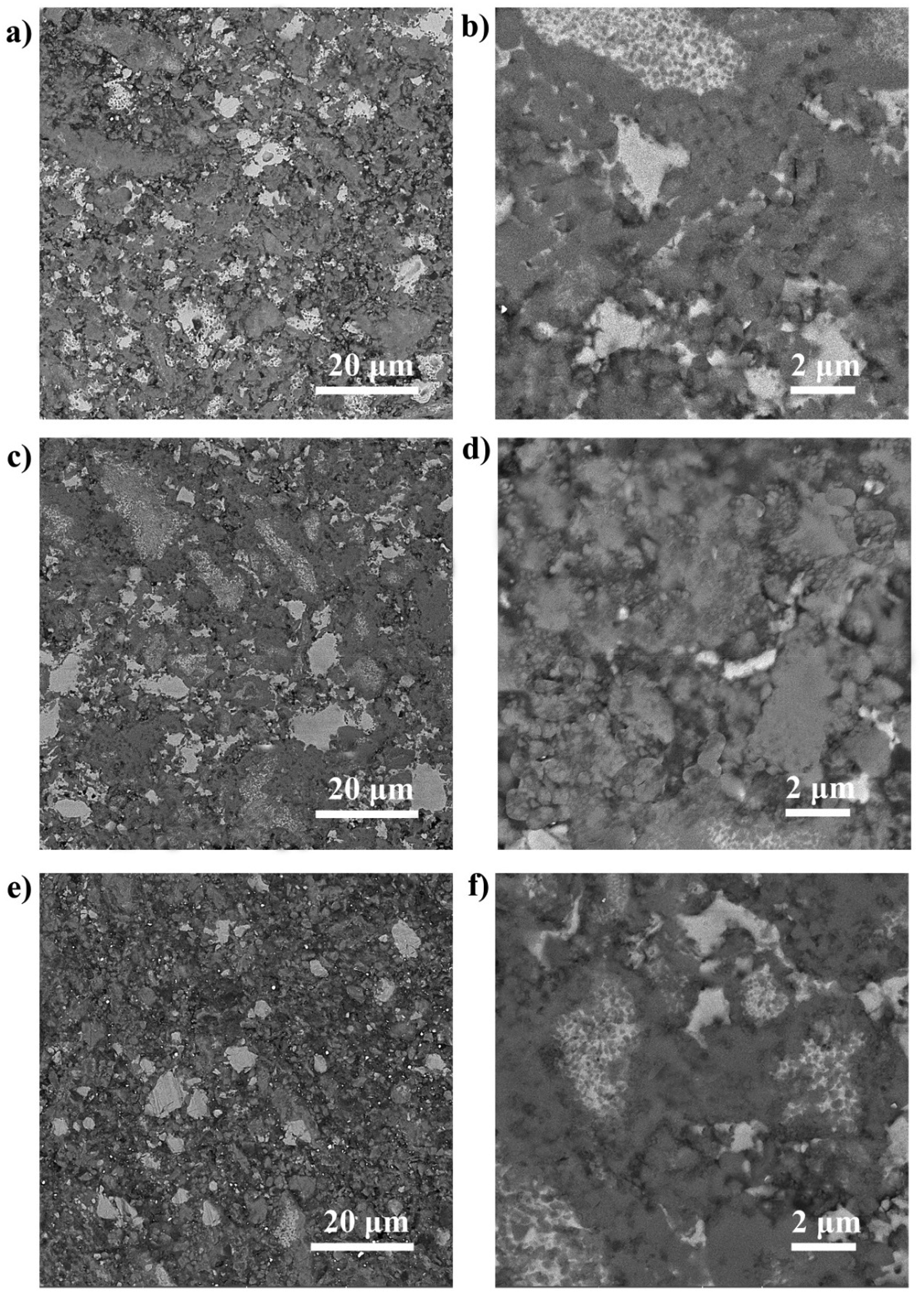
Backscattered electron FESEM micrographs recorded from the surface of the (a)-(b) titanium carbide–30 wt.% iron, (c)-(d) titanium carbide–20 wt.% iron and (e)-(f) titanium carbide–10 wt.% iron coated specimens.
FESEM micrographs reveal the systematic evolution of microstructure with Fe content. Semi-quantitative image analysis indicates a clear trend in the size of the structural features. In the TiC–10 wt% Fe coating, the Fe binder forms fine, discrete particles with an estimated average size of 0.8 μm, located predominantly along TiC grain boundaries. The TiC grains themselves are fine, with an average size of 1.2 μm. As the Fe content increases to 20 wt%, the metallic phase develops a more continuous network, with Fe region sizes increasing to an estimated 2.5 μm. The TiC grains in this coating coarsen to an average size of 2.0 μm. In the TiC–30 wt% Fe coating, the Fe phase becomes highly interconnected, forming large pools with dimensions typically ranging from 4.5 μm. Concurrently, the TiC matrix grains exhibit further moderate coarsening, reaching an average size of 3.0 μm.
Elemental mapping by energy-dispersive X-ray spectroscopy corroborates the phase assignments inferred from imaging: titanium and carbon signals co-localize in the darker matrix regions (consistent with titanium carbide), whereas iron signals concentrate in the brighter islands (Figure 5). The observed distributions in the energy-dispersive X-ray spectroscopy maps are consistent with the designed powder compositions and with the XRD phase identification.

Energy-dispersive X-ray spectroscopy map images conducted at the surface of the titanium carbide–30 wt.% iron, titanium carbide–20 wt.% iron and titanium carbide–10 wt.% iron coated samples.
Taken together, the X-ray diffraction, FESEM and energy-dispersive X-ray spectroscopy results confirm successful synthesis of titanium carbide–iron composite coatings with controlled iron content, homogeneous dispersion of the metallic phase in a titanium carbide matrix, and continuous interfacial contact with the tungsten-carbide–cobalt substrate. Within the resolution limits of the applied characterization techniques, no open porosity or interfacial delamination was detected; these observations support the conclusion that the spark plasma sintering route produced dense, adherent coatings across the examined compositions. Furthermore, the punch displacement–temperature profile (Figure 1(b)) shows the cessation of shrinkage at the final stage of the cycle, corroborating that densification was essentially completed during the spark plasma sintering process.
It is necessary to note that, during spark plasma sintering, the actual temperature at the coating–substrate interface may differ slightly from the nominal set temperature due to the inherent thermal and electrical gradients in the process. Considering the high thermal conductivity of the WC–Co substrate and the limited coating thickness, the temperature difference across the interface is expected to be small. Therefore, the interfacial region may have experienced a slightly higher local temperature than the measured set point of 1500 °C. Based on these considerations, 1500 °C appears to be an appropriate processing temperature, providing effective densification and interfacial bonding without promoting excessive grain growth or undesirable phase formation.
Bonding strength and mechanical behavior
The pull-off tensile testing shows a clear composition-dependent trend in bond strength and mechanical response. Measured bonding strengths are 85 ± 11 MPa (titanium carbide–30 wt.% iron), 70 ± 6 MPa (titanium carbide–20 wt.% iron) and 51 ± 3 MPa (titanium carbide–10 wt.% iron) (Figure 6). Concurrently, the mechanical response becomes less ductile as the iron content is reduced: the coatings show decreasing strain to failure (increased brittleness) with increasing titanium carbide fraction. This trend is consistent with the microstructural balance between a ductile metallic phase that accommodates strain and a hard ceramic phase that provides strength but limited plasticity. Increasing the ceramic fraction reduces the capacity for plastic accommodation at the interface and within the coating bulk, thereby promoting nucleation and propagation of microcracks under tensile loading and reducing the apparent bonding strength in the pull-off configuration.
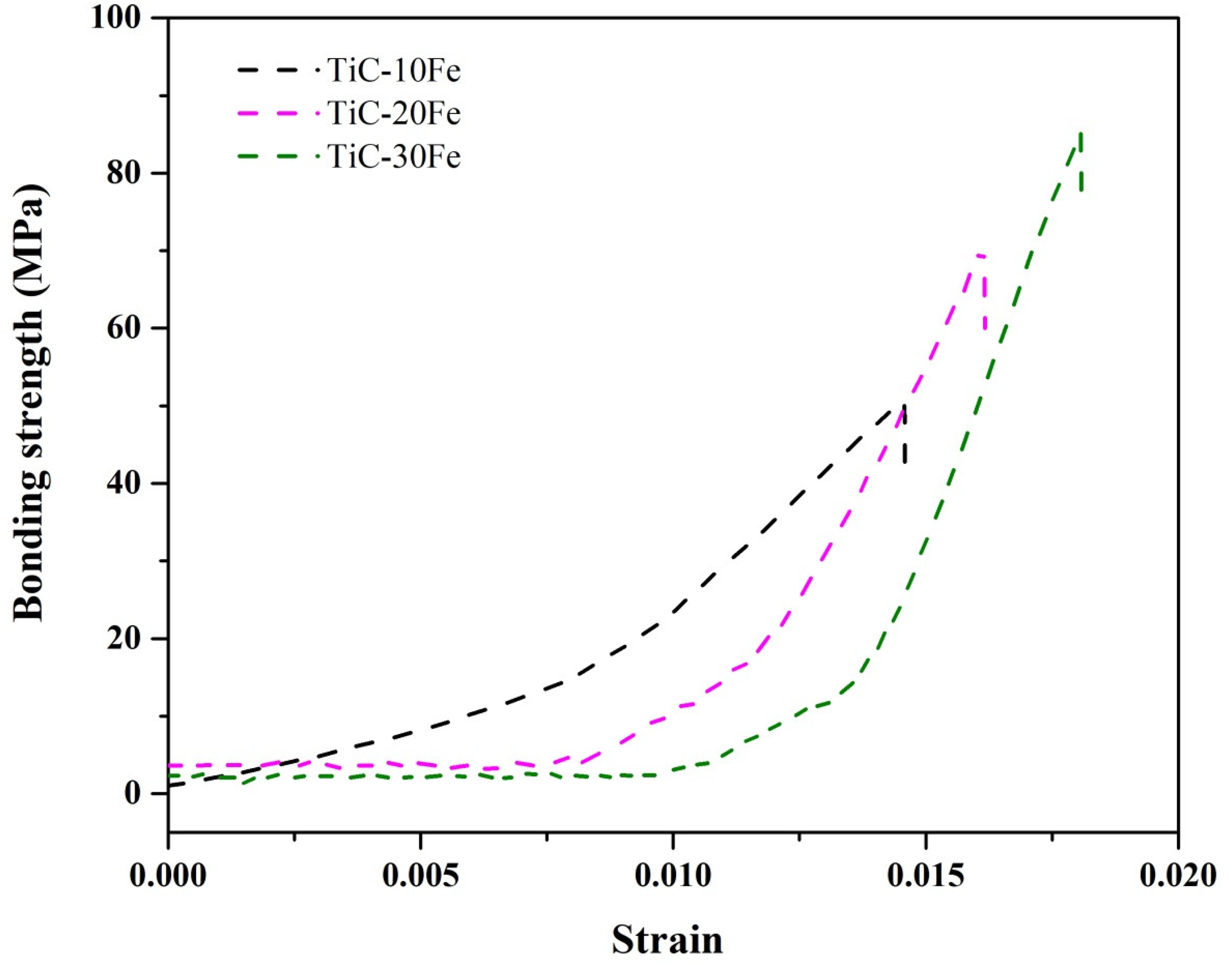
Bonding strength of the titanium carbide–30 wt.% iron, titanium carbide–20 wt.% iron and titanium carbide–10 wt.% iron coated specimens during the pull-off test.
The decrease in pull-off strength with decreasing iron content can be rationalized by a shift in the operative failure mode. At higher Fe contents, the metallic binder forms a more continuous and ductile network which promotes energy dissipation and tends to localize failure within the coating (cohesive failure). As the iron fraction decreases, the coating becomes increasingly carbide-rich and mechanically stiffer, reducing the compliance of the coating and the extent of metallurgical bonding at the interface; consequently, failure becomes increasingly interfacial (adhesive). This interpretation is consistent with the observed microstructural evolution (progressive increase in iron continuity and modest titanium carbide coarsening with increasing iron) and with the measured pull-off strengths across the three compositions.
A number of mechanistic factors can account for the observed composition dependance. First, the metallic binder (iron) acts as a compliant phase that relieves local stress concentrations during mechanical loading; higher iron fractions therefore promote plastic deformation at asperities and across the coating–substrate contact, increasing the energy absorbed prior to crack extension and yielding higher pull-off strengths. Second, with increasing titanium carbide fraction the coating becomes stiffer and more brittle, raising the effective stress intensity at crack tips initiated either within the coating or at the interface. From a fracture-mechanics viewpoint, this change shifts the competition toward crack propagation because the capacity for plastic zone shielding is reduced. 28
Thermo-mechanical considerations are also relevant. Differential thermal expansion between the coating and the tungsten-carbide–cobalt substrate can produce residual stresses during cooling from the sintering temperature. A larger ceramic fraction in the coating likely increases mismatch stresses (due to reduced plastic accommodation), which can pre-load the interface and lower the measured pull-off strength. Conversely, iron-rich coatings, by accommodating more plastic strain during cooling, mitigate part of this residual-stress accumulation. 29
Taken together, these observations highlight the intrinsic trade-off in carbide–metal composite coatings: increasing titanium carbide fraction raises hardness and potential abrasive wear resistance, but it also diminishes strain tolerance and the ability to blunt or arrest cracks, which can weaken mechanical integrity at the coating–substrate interface under tensile or impact-type loading.
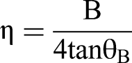
To qualitatively evaluate the lattice microstrain (η) in the TiC–Fe composite coatings, the Stokes and Wilson relation was employed, which relates the broadening of the X-ray diffraction (XRD) peaks to lattice distortions. The equation is expressed as
30
:
Friction behavior and run-in phenomena
The evolution of the coefficient of friction during the pin-on-disk tests reveals a reproducible run-in followed by steady-state behavior for all tested systems (Figure 7). In the early stages of sliding, the friction coefficient increases gradually, a behavior that can be associated with formation of wear debris and surface conditioning phenomena such as particle pull-out and third-body formation. After approximately 100 m of sliding distance, a steady-state friction level is reached, indicating the establishment of a dynamic equilibrium between material removal, tribofilm formation, and progressive surface smoothing.
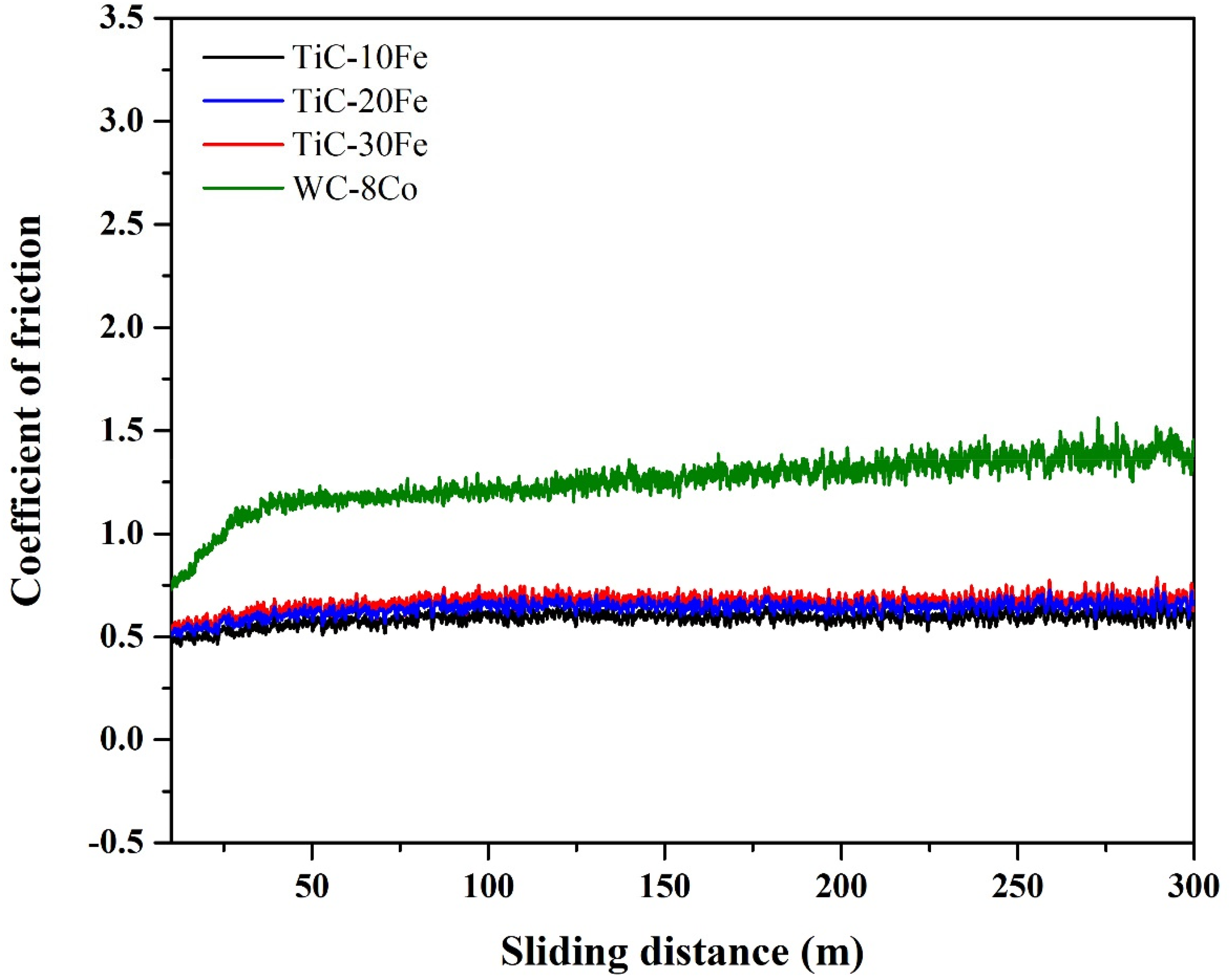
The coefficients of friction vs. sliding distance graphs of the tungsten carbide–cobalt substrate (8 wt.% Co) substrate, titanium carbide–30 wt.% iron, titanium carbide–20 wt.% iron and titanium carbide–10 wt.% iron coated specimens during the pin-on-disk tests.
Compared to the tungsten-carbide–cobalt substrate, the titanium carbide–iron coatings exhibit lower steady-state friction coefficients across the composition range. The substrate displays a consistently higher friction during the test, which can be attributed to several concurrent factors: its high hardness and brittleness promote generation of hard debris (third-body abrasives), it lacks a metallic/oxide combination that can form lubricious tribofilms, and its surface roughness and microstructural features differ from those of the consolidated composite coatings.
A systematic reduction of iron content in the coatings leads to progressively lower friction coefficients. This trend is consistent with the increased continuity of the titanium-carbide-rich matrix, which favors formation of adherent oxide-based tribofilms under sliding. These tribofilms act as a solid-lubricating layer, reducing interfacial shear stresses and thereby lowering the overall coefficient of friction. In contrast, higher iron fractions facilitate plastic accommodation but limit the formation and stability of such tribofilms, resulting in higher friction levels. 31
All tribological tests in this study were conducted under dry sliding conditions at room temperature. Although the formation of oxidation-assisted tribofilms in titanium carbide rich coatings is known to be temperature dependent, the observations made at ambient conditions already indicate the initiation of thin oxide layers that contribute to wear reduction. At this temperature, increasing the titanium carbide fraction provides favorable sites for limited surface oxidation, leading to more continuous tribofilms and promoting a transition toward a more stable, oxidation-assisted wear mechanism. Therefore, it can be concluded that even at room temperature, surface oxidation plays a decisive role in the wear behavior of titanium carbide rich coatings, while its influence is expected to intensify at elevated temperatures.
Worn surface morphology and wear mechanisms
Microscopic inspection of the wear tracks reveals clear composition-dependent dominant mechanisms. In the iron-rich titanium carbide–30 wt.% iron coating, pronounced plastic deformation and extensive subsurface cracking are evident in the worn surface images, indicating that delamination wear is the prevailing mechanism (Figure 8(a) and (b)). The metallic continuity provided by the higher iron fraction promotes localized plastic flow under load; however, it also facilitates crack nucleation and propagation beneath the contact surface, which eventually leads to material detachment.
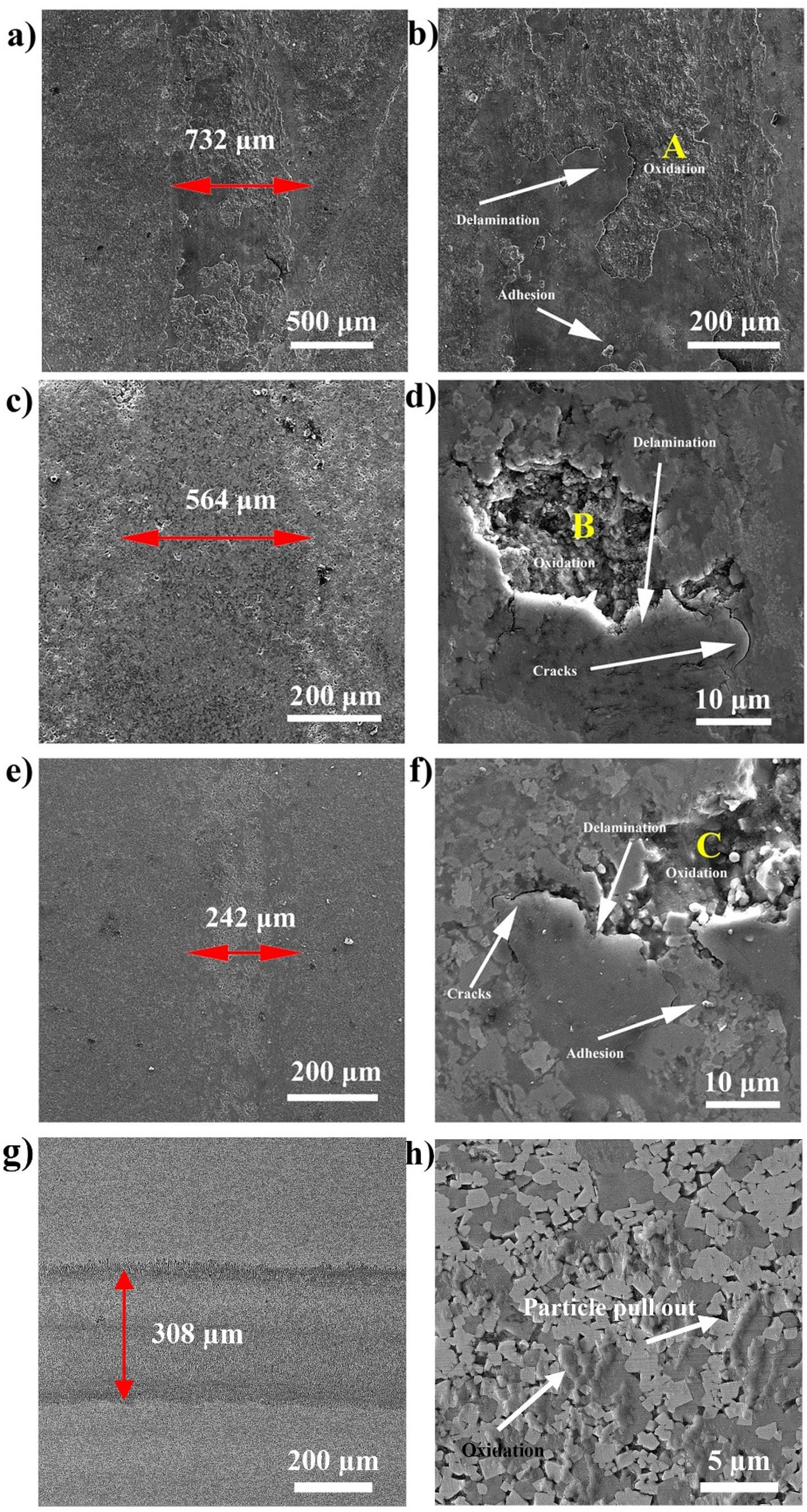
FESEM images of the worn surface of the (a)-(b) titanium carbide–30 wt.% iron, (c)-(d) titanium carbide–20 wt.% iron, (e)-(f) titanium carbide–10 wt.% iron, and (g)-(h) tungsten carbide–cobalt substrate (8 wt.% Co) specimens.
In the titanium carbide–20 wt.% iron and titanium carbide–10 wt.% iron coatings, the extent of plastic deformation and large subsurface cracks is significantly reduced. Instead, worn surface features show evidence of tribofilm formation and adherent oxide layers, which act as a barrier to further material removal. Although small cracks parallel to the surface are still observed across all compositions—consistent with subsurface tensile stresses in brittle microstructures—the reduced size and density of such cracks in titanium carbide–rich coatings indicate improved crack resistance due to the protective tribofilms.
Comparative inspection of the tungsten-carbide–cobalt substrate shows severe wear features including oxidation, debris accumulation, and particle pull-out (Figure 8(g) and (h)). These features align with the higher friction measured for the substrate and suggest a wear regime dominated by a combination of oxidation and third-body abrasion. Despite its relatively high hardness, the brittle nature of the substrate facilitates particle detachment, which in turn acts as abrasive debris that accelerates wear.
Energy-dispersive X-ray spectroscopy of the worn regions indicates greater oxide contents in the titanium carbide–20 wt.% iron and titanium carbide–10 wt.% iron coatings compared with the titanium carbide–30 wt.% iron sample (Figure 9). This observation supports the interpretation that oxidation-assisted tribofilm formation becomes increasingly dominant as the titanium-carbide fraction rises. The presence of these protective oxide layers explains both the lower friction and the reduced wear rate observed in the titanium carbide–rich coatings.
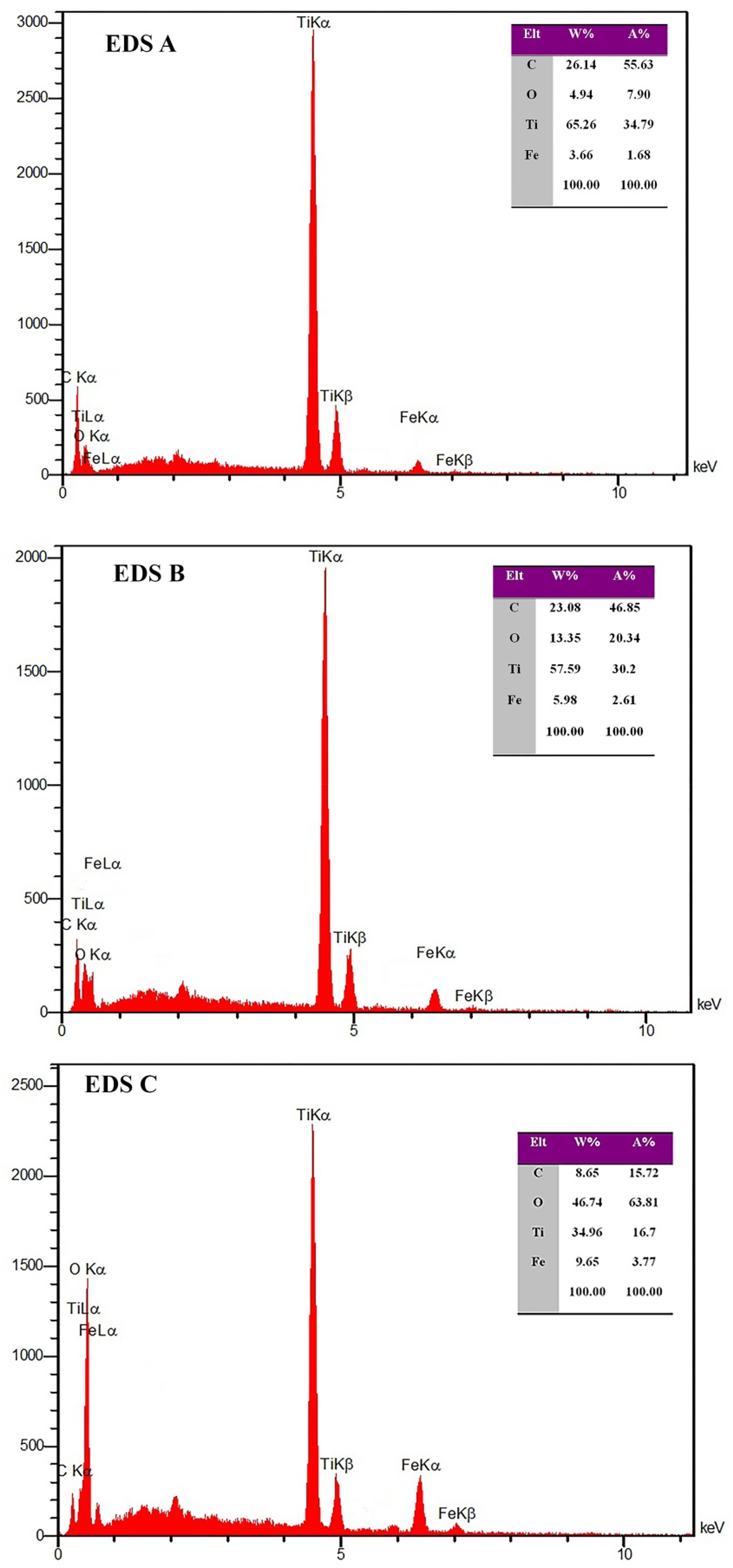
Energy-dispersive X-ray spectroscopy spectra from the corresponding regions indicated in fig. 8.
The surface energy-dispersive X-ray spectroscopy obtained from the worn tracks revealed a significant enrichment of oxygen and titanium, accompanied by smaller amounts of iron, confirming the formation of an oxide-based tribofilm during sliding. Based on the titanium–iron–oxygen ratios and supported by previous studies on titanium carbide–iron systems, this tribofilm is mainly composed of titanium oxide (TiO₂) with minor contributions from iron oxide (Fe₂O₃/Fe₃O₄) phases. The mixed oxide layer is likely nanocrystalline to partially amorphous in structure and forms in situ as a result of oxidation-assisted reactions under frictional heating. Such a tribofilm acts as a protective, self-lubricating barrier that limits direct contact between asperities, thereby lowering both the coefficient of friction and the wear rate. The presence of Fe enhances the continuity and adherence of this tribolayer by promoting localized oxidation and diffusion at the sliding interface. Consequently, the improved wear resistance and more stable frictional response observed in the titanium carbide-rich coatings can be attributed to the development of this durable mixed titanium–iron–oxygen tribofilm (Figure 10).
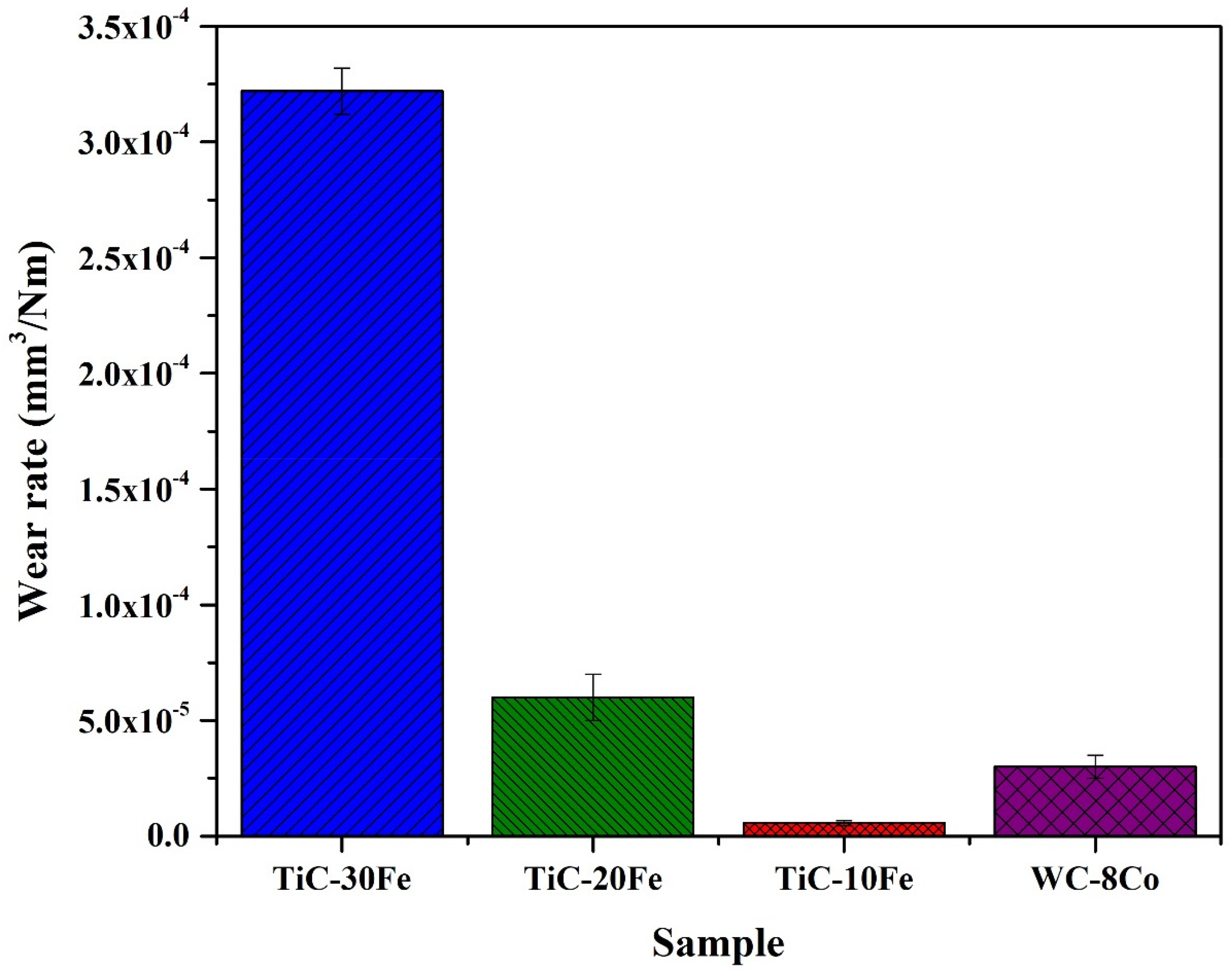
The wear rate plot of the tungsten carbide–cobalt substrate (8 wt.% Co) substrate, titanium carbide–30 wt.% iron, titanium carbide–20 wt.% iron and titanium carbide–10 wt.% iron specimens.
Quantitative measurements of wear track width further corroborate these trends. Track widths decrease systematically with decreasing iron content: 732 ± 24 µm (titanium carbide–30 wt.% iron), 564 ± 31 µm (titanium carbide–20 wt.% iron), and 242 ± 35 µm (titanium carbide–10 wt.% iron). For comparison, the tungsten-carbide–cobalt substrate exhibits a wear track width of 308 ± 13 µm, which is narrower than the iron-rich coatings but still wider than the titanium carbide–10 wt.% iron coating. These observations suggest that, although the substrate benefits from high intrinsic hardness, the presence of severe abrasive and oxidative wear mechanisms leads to intermediate wear resistance. In contrast, the titanium carbide–10 wt.% iron coating combines relatively high hardness with the ability to form protective tribofilms, producing the most favorable performance in terms of wear resistance.
Hardness, wear rates and their interrelation
Microhardness values measured on the coatings are 11.01 ± 0.15 GPa (titanium carbide–30 wt.% iron), 13.97 ± 0.22 GPa (titanium carbide–20 wt.% iron) and 15.01 ± 0.30 GPa (titanium carbide–10 wt.% iron). The tungsten carbide–cobalt substrate has a hardness of 15.4 ± 0.35 GPa. The increase in hardness with decreasing iron content is consistent with the higher volume fraction of the hard titanium-carbide phase. It is worth noting that with a 200 g Vickers load the indentation diagonal is estimated to lie in the range 13.5–19.1 µm and the corresponding indentation depth in the range 1.9–2.7 µm. These indentation depths are markedly smaller than 10% of the coating thickness (∼84–89 µm); therefore, substrate influence on the reported hardness values is considered negligible.
Specific wear rates computed from measured worn volumes and test parameters show a strong decrease with decreasing iron content: 3.22 × 10⁻⁴ mm3·N−1·m−1 (titanium carbide–30 wt.% iron), 6.11 × 10⁻⁵ mm3·N−1·m−1 (titanium carbide–20 wt.% iron) and 5.61 × 10⁻⁶ mm3·N−1·m−1 (titanium carbide–10 wt.% iron). The tungsten carbide–cobalt substrate exhibits a wear rate of 3.11 × 10⁻⁵ mm3·N−1·m−1. These trends largely follow the expectation from Archard's relation that wear tends to decrease as hardness increases, but the comparison with the substrate demonstrates that hardness alone does not fully determine wear performance: despite the substrate's slightly higher hardness, its wear rate is higher than that of titanium carbide–10 wt.% iron, indicating important contributions from tribofilm formation and steady-state friction level.
To provide a quantitative measure of the role of mechanisms beyond hardness, Table 2 summarizes the measured hardness (H), specific wear rate (Q) and the corresponding dimensionless wear coefficient (K) derived from Archard's relation in the form Q = K/H, which gives K = Q.H when Q is reported in mm3·N−1·m−1 and H in GPa. The resulting K values are therefore dimensionless and allow direct comparison of the effective wear behavior across samples.
The computed K values decrease markedly with decreasing iron content: K≈3.545 × 10⁻³ (titanium carbide–30 wt.% iron), 8.536 × 10⁻⁴ (titanium carbide–20 wt.% iron), and 8.421 × 10⁻⁵ (titanium carbide–10 wt.% iron), while the tungsten carbide–cobalt substrate displays ≈4.789 × 10⁻⁴. These numbers demonstrate that the exceptionally low wear rate of the titanium carbide–10 wt.% iron coating cannot be explained by hardness alone: although titanium carbide–10 wt.% iron and the substrate have similar hardness, the titanium carbide–10 wt.% iron coating exhibits a substantially lower K, indicating an additional contribution from protective mechanisms (for example, oxidation-derived tribofilm formation and reduced third-body abrasion). Conversely, the large K of titanium carbide–30 wt.% iron reflects the combined effect of lower hardness and deleterious wear mechanisms such as delamination and intensive third-body abrasion, which increase the effective wear coefficient. Reporting K makes the comparison quantitatively explicit and supports the mechanistic interpretation that reducing iron content both increases hardness and shifts the dominant wear mechanism from delamination toward oxidation-assisted tribofilm formation, thereby reducing the effective wear coefficient and improving wear performance. 32 The results indicate that the dominant wear mechanism shifts from adhesive/delamination wear in iron-rich coatings to oxidation-assisted wear with tribofilm formation in titanium carbide-rich coatings within the compositional range between 20 and 30 wt.% iron, corresponding to approximately 13.6–21.2 vol.% iron. This range represents the critical transition region where the metallic binder achieves sufficient continuity to accommodate local strain and promote stable tribofilm formation, thus enhancing wear resistance under dry sliding conditions.
It should be noted that a slight variation in coating thickness was observed (∼842 to 894 μm). However, given that the indentation depths for hardness and the wear track depths were less than 2% and 1.8% of the minimum coating thickness, respectively, the influence of this thickness variation on the comparative mechanical and tribological results is considered negligible.
Comparison to alternative coating processes and practical implications
The coatings produced by spark plasma sintering in this study show higher hardness and bond strength than typical values reported for thermal spray or plasma spray coatings. For example, plasma-sprayed coatings reported in the literature display hardness values around 560 Vickers (≈5.5 GPa) and bond strengths in the order of 40 MPa, substantially lower than the values obtained here. 21 The superior performance of spark plasma sintering derived coatings is attributable to the simultaneous application of temperature and uniaxial pressure in a vacuum environment, which promotes rapid densification, minimizes porosity, and fosters strong interparticle and interfacial bonding. These attributes make spark plasma sintering a promising route to produce high-performance titanium-carbide–iron composite coatings for tooling and wear applications where the combination of adhesion, hardness and controlled tribological behaviour is required.
The wear behavior of the coatings is expected to depend on the tribological environment. The titanium carbide–iron coatings are anticipated to exhibit superior performance compared with tungsten carbide–cobalt under elevated temperature or boundary lubricated conditions, where the oxidation-assisted formation of a stable titanium–iron–oxygen tribofilm reduces friction and material loss. Their enhanced chemical stability also suggests improved resistance in corrosive or erosive–abrasive environments, while the ductile Fe binder can absorb impact and thermal stresses under cyclic or high-load conditions, thereby mitigating crack propagation and improving coating durability.
Conclusions
X-ray diffraction and microstructural analyses confirm in-situ formation of titanium carbide–iron composite coatings with no detectable secondary crystalline phases or open porosity.
Decreasing the iron content reduces coating adhesion: pull-off strength decreases from 85 ± 11 MPa at 30 wt.% iron to 70 ± 6 MPa at 20 wt.% iron and to 51 ± 3 MPa at 10 wt.% iron, indicating increased brittleness at lower metallic-binder fractions.
Hardness increases as iron content is reduced (approximately 11.01 ± 0.15 GPa at 30 wt.% iron, 13.97 ± 0.22 GPa at 20 wt.% iron, and 15.01 ± 0.30 GPa at 10 wt.% iron), which contributes to improved resistance to material removal.
Specific wear rates and steady-state friction coefficients decrease markedly with lower iron content; the dimensionless wear coefficient K (derived from Archard's relation) indicates that the superior performance of the 10 wt.% iron coating results from both higher hardness and additional protective mechanisms, notably oxidation-derived tribofilm formation and reduced third-body abrasion.
For practical applications, the coating containing approximately 10 wt.% iron offers the best compromise between high hardness, low friction and minimal wear, whereas iron-rich coatings provide higher adhesion but inferior tribological performance.
Footnotes
Acknowledgments
Not Applicable
Author contributions
Mrs. S. Rezaei designed and performed the experiments.
Prof. Mansour Razavi verified the analytical methods and wrote the paper.
Prof. M. Alizadeh collected the data.
Dr F.S. Torknik conceived and planned the experiments.
Declaration of conflicting interests
The authors declared no potential conflicts of interest with respect to the research, authorship, and/or publication of this article.
Funding
The authors received no financial support for the research, authorship, and/or publication of this article.